L-58------
L-5A
CHANNEL 4
CHANNEL 3
CHANNEL 2
~~~~~~¥-.t--ANT.
SECT
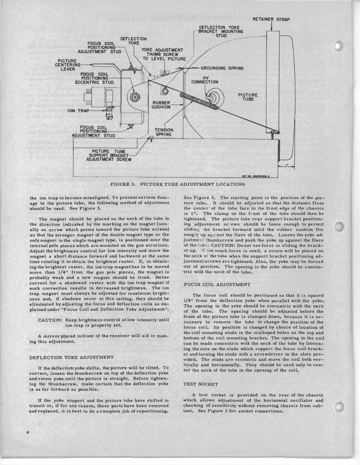
.
L-2A
V=VIDEO
S=SOUND v s
-SOLID
LINE INDICATES
OPTIMUM
RESPONSE.
'fU1"'·"""'~~-
L-28
REAR
VIEW OF
===i==?===?=?=='~,d;::-,t~~~=L=-=2=C=
OSC.
SECTION
---DOTTED
LINES INDICATES
PERMISSIBLE VARIATION.
FIGURE
10.
RF
RESPONSE
CURVES
CHANNELS
2-6
L-4A
""'---L-48
......_
___
L-4C
L-4M
FIGURE
9.
ANTENNA,
RF
AND
OSCILLATOR
COIL
LOCATIONS
NOTE:
A
convenient
method
of
determining
whether
a
coil
is
tuned
correctly
is
to
insert
a
brass
or
iron
slug
into
the
coil.
Brass
decreases
and
iron
increases
the
inductance.
12.
After
channel
6
has
been
aligned,
.
progress
downward
through
channel
2.
CAUTION:
Make
certain
th
e s
tation
selector
switch
is
on
the
correct
channel
before
checking
band-
pass.
OSCILLATOR
ADJUSTMENT
1.
Put
oscillator
back
in
circuit.
2.
Remove
the
short
from
the
AGC
circuit
and
apply
a
-3
volt
battery
bias
to
the
AGC
bus.
3.
Move
the
scope
to
the
test
socket
on
the
chassis
rear
with
the
high
side
connected
to
pin
4
and
the
low
side
to
pin
5
(chassis).
4.
Set
the
contrast
control
at
minimum
(counterclock-
wise).
5.
Remove
the
fine
tuning
knob
and
turn
shaft
until
the
slot
is
in
a
horizontal
position.
This
represents
the
mid-capacity
position.
6.
Turn
station
selector
switch
to
channel
12.
7.
Set
the
sweep
generator
on
channel
12
with
a
center
frequency
of
207
me
and
at
least
a
lZ
me
sweep.
Keep
the
output
low
enough
to
show
no
evidence
of
limiting
in
the
overall
response
curve.
NOTE:
Before
aligning
the
oscillator
section,
make
FIGURE
11.
RF
RESPONSE
CURVES
CHANNELS
7-13
certain
the
3.
3
microhenry
choke
(L-8)
in
the
mixer
grid
is
dressed
away
from
the
2
mmf
ca-
pacitor
(C-16)
tied
to
the
same
grid.
8.
Introduce
a
marker
corresponding
to
the
sound
car-
rier
of
channel
lZ
(Z09.
75
me).
9.
Adjust
oscillator
ceramic
trimmer
so
that
the
sound
marker
falls
into
the
21.9
me
trap
dip
in
the
response
curve.
10.
Turn
generator
and
station
selector
to
channel
9
with
the
fine
tuning
shaft
slot
still
in
the
horizontal
posi
-
tion.
11.
Spread
or
compress
the
3-turn
coil
located
in
the
center
of
the
oscillator
plate
(L
-
4M,
Figure
9)
so
that
the
sound
marker
for
channel
9
falls
into
the
Z7.
3
me
trap
dip
in
the
response
curve.
As
the
os-
cillator
is
tuned
below
the
carrier
on
channels
7,
8,
9 &
10,
the
Z7.
3
me
trap
will
be
in
the
same
position
as
the
Zl.
9
me
trap
in
step
9.
lZ.
Repeat
steps
6,
7,
8 &
9.
13,
Turn
generator
and
station
selector
to
channel
13.
14.
Turn
fine
tuning
trimmer
so
that
the
sound
marker
for
channel
13
falls
into
the
Zl.
9
me
trap
dip
of
re-
sponse
curve.
The
slot
in
the
fine
tuning
shaft
should
not
have
moved
more
than
30°
from
the
horizontal
position
to
accomplish
this
(each
number
on
the
sta-
tion
selector
knob
represents
30°).
15.
U
more
than
a
30°
change
in
fine
tuning
trimm
e r
was
needed
in
step
14,
adjust
channel
13
oscillator
coil
9
Scanned by mbear2k - Jan 2012