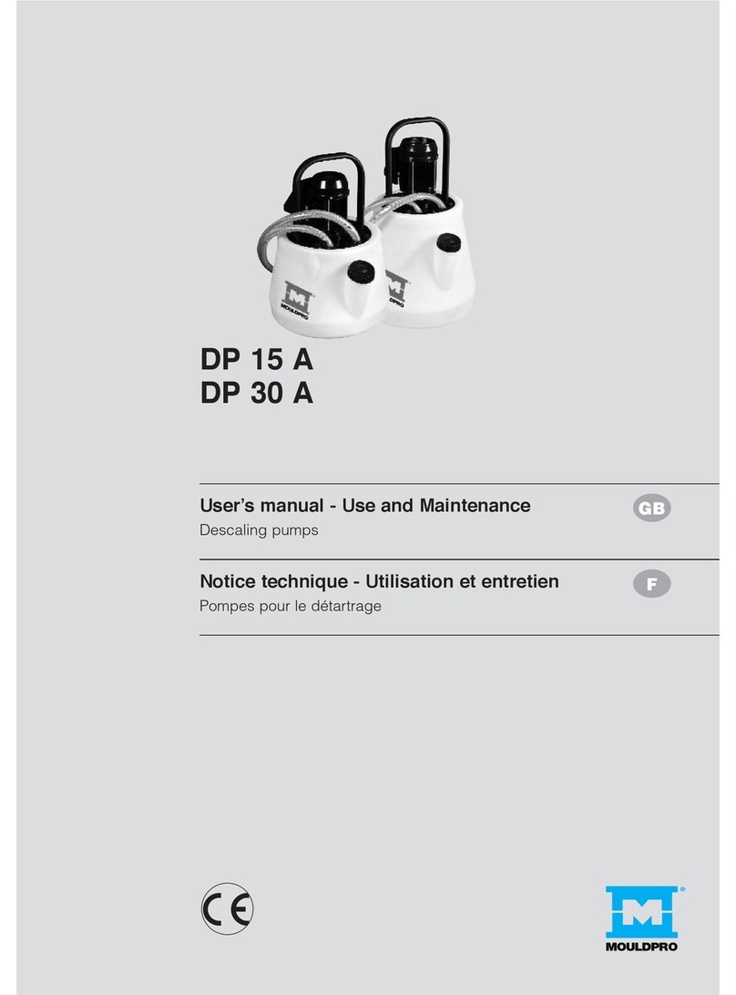
MOULDPRO DP15M User manual

DP 15 M
DP 30 M
User’s manual - Use and Maintenance
Descaling pumps
Notice technique - Utilisation et entretien
Pompes pour le détartrage
GB
F
Bedienungs- und Wartungshandbuch
Entkalkungspumpen
D


ENGLISH
3
Dear Customer, thank you for choosing a MOULDPRO descaling pump.
MANUAL
This manual is a safe guide for the use of the pump. Please read it carefully in all its parts before use.
This manual contains important information for the proper working and use of the equipment.
MOULDPRO reserve the right to introduce any future changes without notice or replacement.
PRELIMINARY INSPECTION
Upon receipt of the pump, take it out from the carton and check it is in perfect condition.
Also check that the data on the rating plate correspond to required ones (please see section
3 “Technical Features”). For any problem, immediately contact the supplier specifying the kind
of fault.
In case of doubt about the safety of the machine, do not use it.
DESCRIPTION
Vertical axis pumps with tank for descaling heat exchangers, pipes, coils and any similar scaled situation.
Pumps are supplied ready to use, in strong carton boxes with related user’s manual.
Below are the main deposits which can be removed with these pumps:
- scale deposits.

4
CONTENTS
1 - REGULATIONS – CE MARK p. 5
2 - THE ADVANTAGES OF THE PUMPS WITH FLOW REVERSER p. 5
3 - TECHNICAL FEATURES p. 6
4 - CUSTOMER SERVICE p. 6
5 - USE p. 6
Precautions p. 7
6 - SAFETY INSTRUCTIONS p. 7
7 - DESCALING CHEMICALS p. 8
8 - EXPLODED VIEWS
DP 15 M p. 9
DP 30 M p. 10
9 - DIRECTIONS FOR DISPOSAL p. 11
10 - WARRANTY TERMS AND AFTER-SALE ASSISTANCE CONDITIONS p. 11

ENGLISH
5
ENGLISH
1 - REGULATIONS – CE MARK
Declaration of Conformity
The pumps are in conformity with the following European Directives, Laws and Regulations:
Low Voltage Directive:
73/23/EEC
93/68/EEC
Electromagnetic Compatibility Directive:
89/336/EEC
92/31/EEC
93/68/EEC
93/97/EEC
Directives RoHS and WEEE:
02/98/EEC
02/96/EEC
03/108/EEC
QUALITY
MOULDPRO equipments are manufactured with high-quality acid-resistant materials and submitted to
severe operating tests.
Follow these instructions to avoid any operating and servicing problems.
2 - THE ADVANTAGES OF THE PUMPS WITH FLOW REVERSER
Time and, above all, temperature increase make calcium
salts, usually present in water, precipitate in the form of
microcrystals and settle on metallic surfaces of pipes,
plant coils and heat exchangers, thus reducing flow rate
and thermal efficiency.
To restore the original plant performance it is necessary
to carry out a descaling with specific products and
equipments.
The flow reverser device attacks scale on both sides, thus
making descaling particularly fast (as the normal dissolving
action is combined with the detachment in flakes of the
scale, made friable from the double attack) and effective,
even when pipes and exchangers are almost totally
clogged.
fig. 1 - Clockwise
circulation
fig. 2 - Counterclockwise
circulation

6
4 - CUSTOMER SERVICE
For enquiries on spare parts, please specify serial number of pump (shown on product and
carton).
5 - USE
5.1 - How to prepare the pump and check the seal
- Fill the tank with enough water to ensure that the pump rotor
housing is submerged during operation.
- Screw the outer ends of the flexible hoses securely to the
exchanger to be descaled.
- Connect the power cable to a single-phase 230 V power
supply.
- Switch on the pump and check the seal of the hose fittings
on the exchanger and on the pump. In case of leaks of liquid,
check hoses and fittings and replace the defective components,
if necessary.
- When seal is safe, switch off the pump.
- If necessary, add more acid by referring to the dilution specified
in the data sheet of the product.
5.2 - Descaling
- Switch on the pump.
IMPORTANT: During use, the tank cap should remain open to allow for the passage and elimination of
the gas evolved during descaling. Check that the foam level does not exceed the maximum filling level.
- Periodically move the handle of the flow reverser from one stop to the other. By attacking scale from both
sides it is possible to clean piping which is almost totally obstructed and descaling time is considerably
reduced.
- Scale removal can be considered complete when bubbles no longer form in the return pipe and the
solution is still acidic.
3 - TECHNICAL FEATURES
121.031.10 DP 15 M 15 35x48 14 48 0,20
121.080.10 DP 30 M 24 40x63 20 90 0,45
Dimensions Max
Code Item Tank L x H Head* flow rate HP
(l) (cm) (w.c.m.) (l/min)*
DESCALING PUMPS (with flow reverser)
* Data referred to the pump body outlet.

ENGLISH
7
5.3 - How to clean the pump
- After descaling REMOVE THE DESCALING LIQUID FROM THE TANK and wash out the pump by
circulating clean water through it for at least 10 minutes.
PRECAUTIONS
Only use MOULDPRO chemicals in order to ensure good working and avoid damaging the
equipments.
Once the lifetime of the pump has expired, do not dispose of it with household
waste. The pump must be recycled in authorized centres and can be assimilated to a
household appliance.
During handling lift the pump and do not drag it in order to avoid damages to the tank.
Temperature of the descaling solution must never exceed 50 °C.
Flexible hoses and fittings can be damaged in time; make sure to check the seal whenever using
the pump, as indicated in the pump preparation instructions.
6 - SAFETY INSTRUCTIONS
- Before installing the motor pump, make sure the power supply is fitted with grounding and
complies with the regulations.
- Avoid using the pump in places where there are liquids, gases, flammable powders or risk of explosion.
- Before plugging in the pump to the outlet, make sure the switch is off.
- The outlet must be suitable for the plug of the pump. Do not use non CE-marked defective outlets.
- Use (CE) approved extensions, only if necessary.
- Do not use plug adapter. Do not carry out any modifications to the plug nor to the electrical cable.
- Pump shall always kept in perfect efficiency.
- During maintenance operations, check the switch is off and the plug is not connected.
- All maintenance operations must be carried out by the authorized Technical Assistance Service.
- Only use MOULDPRO original spare parts.
- Do not carry out any modifications to the pump if not authorized by MOULDPRO Technical Department
(ask for written authorization).
- The warranty is not valid if the pump is repaired by personnel not authorized by the manufacturer, that
also means operating with unsafe and potentially dangerous equipment.
- Keep children and unauthorized persons away from the pump.
- Keep the pump out of reach of children and unauthorized persons.
- Do not use the pump if tired or under the effect of alcohol, medicines or drugs, do not eat or smoke.
- When using the pump, wear overalls, do not wear jewellery, keep hair away from the pump.
- When handling descaling liquids, be very careful. It is necessary to use Individual Protection Equipment
(IPE).

8
7 - CHEMICALS
Copper Steel Stainless
Aluminium
Brass Tin Light
Galvanised
steel alloys iron
DESCALING CHEMICALS
REMOVER LIQUID • •
Concentrated descaling liquid
with powerful reaction for
systems and heat exchangers.
REMOVER PLUS LIQUID • •
Concentrated descaling liquid
(non-fuming), with degreasing
action, for systems and heat
exchangers.
REMOVER PLUS POWDER • • • • •
Concentrated descaling powder
(non-corrosive, non-fuming) for
systems and heat exchangers.
NEUTRALIZING CHEMICALS
NEUTRALIZER • • • • • • • •
Neutralizing powder to remove
residual acidity after descaling
systems and heat exchangers.
Also suitable for neutralizing
descaling chemicals after use,
thus making it possible to
drain them.

ENGLISH
9
8 - EXPLODED VIEWS
75
70
71
72
73
74
1
2
4
5
6
7
53
9
36
10
12
13
15
17
19
41
40
44
45
43
92
42
90
32
91
30
25
21
46
24
28
29
47
64
8
23
26
1. Plastic handle
2. Motor 220/50
4. Brass nut 6 MA
5. PVC blind nut 16 MA
6. Circlip
7. Plastic washer
8. O-Ring for rotor/ impeller
9. PP bolt 12 MA
10. Flange + pump body
12. Shaft sleeve
13. PP rotor/ impeller
15. PP cover
17. PP bolt 8 MA/ 10 MA
19. Tank
21. Pipe fitting 1/2 x 16
23. Tank cap
24. O-Ring for motor flange
25. Flow reverser
26. O-Ring for rotor cover
28. Delivery hose
29. Return hose with pipe fitting
30. Transparent hose m. 2x2 +
fitting 1/2”
32. Male cover – thread 1/2
36. EPDM seal 30x15
40. Flow reverser handle/lever
41. Flow reverser top plate
42. Flow reverser body
43. Flow reverser paddle
44. O-Ring for flow reverser
top plate
45. O-Ring for flow reverser
paddle
46. Pipe fitting 1/2 x 3/4 x 16
47. Pipe fitting 3/4 x 16
53. O-ring 11x3 for shaft cover
sleeve
64. Threaded elbow 1/2 x 3/4
70. Motor fan cover
71. Motor fan
72. Seal bearing
73. Switch
74. Motor flange
75. Screw for fan cover
90. Thread adaptors
91. Hose end fitting 1/2
92. Hose securing ring 3/4
DP 15 M
45120006
47180050
45125021
45175010
45282050
45220010
45280130
45330027
47050010
45250050
47140030
45422040
45340110
47200550
45340255
60012005
45422150
60017015
45540020
47200540
45500010
45295012
45155010
45340130
45340140
45215010
45245010
45165010
60006010
45256040
45370010
60033010
60018012
45370060
45370058
45340240
60031015
45615030
45370062
45180020
45340145
45540097
45340063

10
41
40
44
45
43
92
42
90
91
30
25
46
21
24
28
29
47
64
8
26
23
75
70
71
72
73
74
1
2
4
5
6
7
53
9
10
12
13
15
17
19
1. Plastic handle
2. Motor 220/50
4. Brass nut 6 MA
5. PVC blind nut 16 MA
6. Circlip
7. Plastic washer
8. O-Ring for rotor/ impeller
9. PP bolt 12 MA
10. Flange + pump body
12. Shaft sleeve
13. Rotor/ impeller
15. PP cover
17. PP bolt 10 MA
19. Tank
21. Pipe fitting 1/2 x 16
23. Tank cap
24. O-Ring for motor flange
25. Flow reverser
26. O-Ring for rotor cover
28. Delivery hose
29. Return hose + pipe fitting
30. Transparent hose m. 2x2 +
fitting 1/2
40. Flow reverser handle/lever
41. Flow reverser top plate
42. Flow reverser body
43. Flow reverser paddle
44. O-Ring for flow reverser top
plate
45. O-Ring for flow reverser
paddle
46. Pipe fitting 1/2 x 3/4 x 16
47. Pipe fitting 3/4 x 16
53. O-Ring for shaft cover sleeve
64. Threaded elbow 3/4
70. Motor fan cover
71. Motor fan
72. Seal bearing
73. Switch
74. Motor flange
75. Screw for fan cover
90. Thread adaptors
91. Hose end fitting 1/2
92. Hose securing ring 3/4
DP 30 M
45120020
47180050
45125025
45175020
45282010
45220021
45280120
45330045
47050010
45250050
47140040
45422045
45340140
47200550
60012020
45422175
60017020
45540020
47200540
45500030
45295012
45155010
45340130
45340140
45215010
45245010
45165010
60006010
45370010
60033010
60018012
45370058
45370060
45340240
60031020
45615030
45370062
45180020
45340145
45340063
45540097

ENGLISH
11
9 - DIRECTIONS FOR DISPOSAL
In accordance with the WEEE directive 2002/96/EC on waste electrical and electronic
equipment, the pump, when no longer used, shall be disposed of in a RAEE – WEEE
collection centre authorized for disposal of waste electrical and electronic equipment,
or directly contact your dealer.
10 - WARRANTY TERMS AND AFTER-SALE ASSISTANCE CONDITIONS
MOULDPRO guarantee that the equipments sold are free from designing, manufacturing and material
defects, under normal operating conditions and according to the directions contained in the instructions
manual supplied with the equipment.
In compliance with the directive 1999/44/CE valid in the EEC countries, the warranty rights apply only to
the purchaser.
MOULDPRO, placed in Baltorpbakken 10, DK - 2750 Ballerup - Denmark, guarantee the equipments
against any conformity defects appearing within 24 (twenty-four) months from the purchase date, even
when warranty operations have been carried out during this period, if only proved by a document.
The warranty covers all components of the equipment and provides for the repairing or, if necessary, the
free replacement of those parts that, according to your Dealer, have conformity defects.
The warranty does not cover the aesthetic parts and the parts subject to wear and tear, nor does it cover
all damages or failures whose cause is not due to the manufacturer, such as: transport, wrong installation
or maintenance, tampering, sudden changes of electric voltage and/or hydraulic pressure, thunderbolts,
corrosions, excess of humidity, accidental bumps or events beyond our control.
The warranty is valid only if the equipments have been installed, used and properly maintained according
to all directions supplied by MOULDPRO in the instructions manual attached to the equipment.
Should any conformity defects of the product be found during the warranty period, the Customer shall
notify the Dealer to agree upon the terms of repairing and/or replacing of the product.

12
Cher Client, nous vous remercions d’avoir choisi une pompe à détartrer MOULDPRO .
NOTICE TECHNIQUE
Cette notice représente un guide sûr pour l’utilisation de ces pompes MOULDPRO, il est donc nécessaire
de bien en lire chaque partie avant de les utiliser.
Cette notice contient des informations importantes pour un fonctionnement et une utilisation corrects de
ces appareils.
MOULDPRO se réserve le droit d’apporter des modifications sans obligation de préavis ni de remplacement.
CONTROLES PRELIMINAIRES
Au moment de la livraison, sortir la pompe de l’emballage et en vérifier l’intégrité. Vérifier que les inscriptions
sur l’étiquette correspondent aux caractéristiques choisies. En cas d’anomalie, contacter
immédiatement le fournisseur et lui signaler la nature des défauts.
En cas de doute sur la sureté de l’appareil, ne pas l’utiliser.
DESCRIPTION
Pompes à axe vertical avec réservoir pour la désincrustation des échangeurs, des tuyaux, de tous les
serpentins et de toutes les situations d’entartrement.
Les pompes sont fournies dans de robustes boites en carton avec leur notice d’instructions, prêtes à
l’usage.
Synthèse des dépôts éventuels qui peuvent être éliminés par ces pompes :
- incrustations calcaires.

FRANÇAIS
13
INDEX
1 - NORMES-MARQUE CE p. 14
2 - AVANTAGES DES POMPES AVEC INVERSEUR DE FLUX p. 14
3 - CARACTERISTIQUES TECHNIQUES p. 15
4 - SERVICE ASSISTANCE CLIENTS p. 15
5 - UTILISATION p. 15
Avertissements p. 16
6 - INSTRUCTIONS POUR LA SECURITE p. 16
7 - PRODUITS DETARTRANTS p. 17
8 - VUES ECLATEES
DP 15 M p. 18
DP 30 M p. 19
9 - INSTRUCTIONS POUR L’ELIMINATION p. 20
10 - CONDITIONS DE GARANTIE p. 20

14
1 - NORMES-MARQUE CE
Déclaration de conformité
Ces pompes sont conformes aux Directives, Lois et Règlements européens.
Directive Basse Tension:
73/23/EEC
93/68/EEC
Directive Compatibilité Electromagnétique:
89/336/EEC
92/31/EEC
93/68/EEC
93/97/EEC
Directive RoHS et WEEE:
02/98/EEC
02/96/EEC
03/108/EEC
QUALITE
Nos appareils sont construits avec des matériaux antiacides de la meilleure qualité et sont soumis à des
tests rigoureux de fonctionnement.
La maintenance et le fonctionnement ne créent aucun problème si l’on respecte ces instructions.
2 - AVANTAGES DE LA POMPE AVEC INVERSEUR DE FLUX
Avec l’augmentation de la température, le temps passant, les sels de calcium qui se trouvent normalement
dans l’eau précipitent sous forme de microcristaux et se
déposent sur les surfaces métalliques des tuyaux, des
serpentins des installations et échangeurs de chaleur
avec diminution consécutive du débit et du rendement
thermique.
Pour rétablir les prestations d’origine des installations
il faut effectuer un détartrage avec des produits et des
appareils spécifiques.
Le dispositif inverseur de flux permet d’attaquer les
incrustations des deux cotés, en rendant la désincrustation
particulièrement rapide (en plus de l’action de dissolution
normale, on a un effet de décollement du calcaire sous
forme d’écailles devenu friable à la suite de la double
attaque subie) et efficace, même en présence de tuyaux
et d’échangeurs quasiment bouchés.
fig. 1 - Circulation
dans le sens horaire
fig. 2 - Circulation
dans le sens antihoraire

FRANÇAIS
15
4 - SERVICE ASSISTANCE CLIENTS
A chaque fois que vous appelez il faut spécifier le N° de matricule de la pompe (reporté sur le
produit et sur la boite d’emballage)
5 - UTILISATION
5.1 - PREPARATION DE LA POMPE ET VERIFICATION DE LA TENUE
- Remplir le réservoir avec la quantité d’eau nécessaire
pour maintenir le corps de la pompe submergé pendant le
fonctionnement.
- Visser les bouts des tuyaux flexibles à l’échangeur à détartrer
- Brancher le câble d’alimentation à une prise de courant 220 V
monophasé
- Mettre en marche la pompe grâce à l’interrupteur et contrôler la
tenue des raccords sur l’échangeur et sur la pompe. En cas de
pertes liquides vérifier l’intégrité des raccords et des tuyaux et
pourvoir au remplacement des pièces abimées.
- Quand l’etanchéité est sure éteindre la pompe.
- Ajouter avec précaution la quantité d’acide nécessaire pour
le détartrage en se référant à la dilution spécifiée sur la fiche
technique du produit.
5.2 - DETARTRAGE
- Mettre en marche la pompe grâce à l’interrupteur.
IMPORTANT : Pendant le fonctionnement laisser le bouchon du réservoir ouvert pour permettre aux gaz
qui se forment durant l’opération de détartrage de s’échapper et contrôler que la hauteur de la mousse
ne dépasse pas le niveau maximal de remplissage.
- Actionner périodiquement le levier de l’inverseur de flux d’une marque de pose à une autre. En effet en
attaquant les incrustations des deux cotés on peut détartrer des tuyaux quasiment bouchés et on réduit
les temps d’intervention.
- On peut considérer le détartrage terminé quand dans le tuyau de retour il n’y aura plus de formation de
bulles et la solution sera encore acide.
3 - CARACTERISTIQUES TECHNIQUES
121.031.10 DP 15 M 15 35x48 14 48 0,20
121.080.10 DP 30 M 24 40x63 20 90 0,45
Dimensions
Hauteur*
Débit
Code Article R
éservoir
L x H
d’élévation
max HP
(l) (cm) (m.c.e.) (l/min)*
POMPES POUR LE DETARTRAGE ( avec inverseur de flux)
* Valeurs qui se réfèrent à la sortie du corps pompe

16
5.3 - NETTOYAGE DE LA POMPE
- Une fois terminé le détartrage ENLEVER LE LIQUIDE ANTITARTRE DU RESERVOIR et effectuer un
lavage en faisant circuler de l’eau propre pendant 10 minutes minimum.
AVERTISSEMENTS
Pour garantir un bon fonctionnement et pour éviter des dommages aux appareils utiliser
exclusivement les détartrants « MOULDPRO ».
Une fois terminée la durée de vie de la pompe, ne pas la jeter avec les déchets
domestiques.
La pompe devra être transportée dans un centre autorisé pour le recyclage et elle est
assimilable à un électroménager.
Pendant la manutention soulever la pompe en évitant de la faire glisser pour éviter tout dommage
au réservoir.
La solution détartrante ne doit jamais dépasser la température de 50°C.
Les flexibles et les raccords peuvent s’abimer au cours du temps, prendre soin d’en vérifier à
chaque utilisation l’étanchéité comme cela est indiqué dans les instructions de préparation de la
pompe.
6 - INSTRUCTIONS POUR LA SECURITE
- Avant l’installation de l’électropompe s’assurer que le réseau d’alimentation soit doté de mise
à la terre et soit conforme aux normes
- Eviter l’utilisation de la pompe dans un environnement où se trouvent des liquides, gaz et poudres
inflammables ou à risque d’explosions.
- Avant de brancher la fiche à la prise électrique, s’assurer que l’interrupteur soit éteint.
- La prise de courant doit être adaptée à la fiche de la pompe. Ne pas utiliser de fiches défectueuses ou
non conformes aux normes CE.
- Si cela est nécessaire, utiliser des rallonges homologuées (CE)
- Ne pas employer d’adaptateurs pour prise. Ne pas apporter de modifications à la prise, ni au câble
électrique.
- La pompe doit être maintenue en parfaite efficience
- Durant les opérations de maintenance, contrôler que l’interrupteur soit éteint et que la fiche soit
débranchée.
- Les opérations de maintenance doivent être effectuées exclusivement par le personnel spécialisé
- Utiliser uniquement les pièces de rechange originales MOULDPRO
- Réparer ou faire réparer la pompe par des personnes non autorisées par MOULDPRO comporte la perte
de la garantie et signifie faire fonctionner un appareil peu sûr et potentiellement dangereux.
- Garder la pompe hors de la portée des enfants et des personnes externes.
- Ne pas utiliser la pompe en cas de fatigue, sous l’effet de l’alcool, des médicaments ou des drogues.
- Lors de l’utilisation de la pompe, utiliser une combinaison de travail, ne pas utiliser de bijoux et garder
les cheveux attachés.
- La manipulation de liquides désincrustants demande une grande attention.
- Il faut utiliser les dispositifs de protection individuels.

FRANÇAIS
17
7 - PRODUITS CHIMIQUES
Cuivre Acier Acier Aluminium Laiton Etain Alliages Zingués
inox légers
PRODUITS DETARTRANTS
REMOVER LIQUID • •
Détartrant liquide concentré à
action énergique pour les
installations et les échangeurs.
REMOVER PLUS LIQUID • •
liquide détartrant concentré
( non fumigatoire) action
dégraissante pour les
installations et les échangeurs.
REMOVER PLUS POWDER • • • • •
Détartrant en poudre concentré
( non corrosif, non fumigatoire)
pour les installations
et les échangeurs.
PRODUITS NEUTRALISANTS
NEUTRALIZER • • • • • • • •
Poudre neutralisante pour
l’élimination de l’acidité résiduelle
après la désincrustation des
installations et des échangeurs.
Elle peut être aussi utilisée
comme neutralisant pour les
solutions détartrantes en
permettant la décharge directe
à l’égout.

18
8 - ECLATE
1) Poignée plastique
2) Moteur 220/50
4) Ecrou en laiton 6MA
5) Bague fermée 16 MA en PVC
6) Bague de retenue
7) Rondelle en plastique
8) Joint torique pour turbine
9) Vis en PP, 12 MA
10) Bride + corps pompe
12) tube pour arbre
13) turbine en PP
15) Bouchon du filtre en PP
17) Vis en PP, 8 MA
19) Réservoir
21) Raccord 1/2” x 16
23) bouchon réservoir
24) Joint torique bride moteur
25) Inverseur de flux
26) Joint torique bouchon filtre
28) Tuyau aller
29) Tube retour avec porte-
caoutchouc
30) Tuyau flexible transp. M 2x2 et
raccord 1/2
32) Bouchon male fileté 1/2
36) joint de 30 x 15 EDPM
40) Poignée soupape inverseur
41) Couvercle soupape inverseur
42) corps soupape inverseur
43) registre à papillon inverseur
44) Joint torique couvercle
inverseur
45) Joint torique papillon inverseur
46) raccord porte-caoutchouc 1/2
x 3/4 x 16
47) raccord porte-caoutchouc 3/4
x 16
53) Joint torique pour tube couvre-
arbre
64) Coude fileté de 1/2 ou 3/4
70) Couvre-hélice de ventilation
moteur
71) Hélice de ventilation moteur
72) Palier d’étanchéité
73) Interrupteur
74) Bride moteur
75) Vis couvre-hélice de ventilation
90) Réductions
91) Raccord terminal 1/2”
92) Frette 3/4”
DP 15 M
75
70
71
72
73
74
1
2
4
5
6
7
53
9
36
10
12
13
15
17
19
41
40
44
45
43
92
42
90
32
91
30
25
21
46
24
28
29
47
64
8
23
26
45120006
47180050
45125021
45175010
45282050
45220010
45280130
45330027
47050010
45250050
47140030
45422040
45340110
47200550
45340255
60012005
45422150
60017015
45540020
47200540
45500010
45295012
45155010
45340130
45340140
45215010
45245010
45165010
60006010
45256040
45370010
60033010
60018012
45370060
45370058
45340240
60031015
45615030
45370062
45180020
45340145
45540097
45340063

FRANÇAIS
19
1) Poignée plastique
2) Moteur 220/50
4) Ecrou en laiton 6MA
5) Bague fermée 16 MA en PVC
6) Bague de retenue
7) Rondelle en plastique
8) Joint torique pour turbine
9) Vis en PP, 12 MA
10) Bride + corps pompe
12) tube pour arbre
13) turbine en PP
15) Bouchon du filtre en PP
17) Vis en PP, 8 MA
19) Réservoir
21 Raccord 1/2” x 16
23) bouchon réservoir
24) Joint torique bride moteur
25) Inverseur de flux
26) Joint torique bouchon filtre
28) Tuyau aller
29) Tube retour avec porte-
caoutchouc
30) Tuyau flexible transp. M 2x2
et raccord 1/2
40) Poignée soupape inverseur
41) Couvercle soupape inverseur
42) corps soupape inverseur
43) registre à papillon inverseur
44) Joint torique couvercle
inverseur
45) Joint torique papillon
inverseur
46) raccord porte-caoutchouc
1/2 x 3/4 x 16
47) raccord porte-caoutchouc
3/4 x 16
53) Joint torique pour tube
couvre-arbre
64) Coude fileté de 3/4
70) Couvre-hélice de ventilation
moteur
71) Hélice de ventilation moteur
72) Palier d’étanchéité
73) Interrupteur
74) Bride moteur
75) Vis couvre-hélice de
ventilation
90) Réductions
91) Raccord terminal 1/2”
92) Frette 3/4”
DP 30 M
41
40
44
45
43
92
42
90
91
30
25
46
21
24
28
29
47
64
8
26
23
75
70
71
72
73
74
1
2
4
5
6
7
53
9
10
12
13
15
17
19
45120020
47180050
45125025
45175020
45282010
45220021
45280120
45330045
47050010
45250050
47140040
45422045
45340140
47200550
60012020
45422175
60017020
45540020
47200540
45500030
45295012
45155010
45340130
45340140
45215010
45245010
45165010
60006010
45370010
60033010
60018012
45370058
45370060
45340240
60031020
45615030
45370062
45180020
45340145
45340063
45540097

20
9 - INSTRUCTIONS POUR L’ELIMINATION
Selon les la directive WEEE 2002/96/EC sur les déchets électriques et électroniques,
lorsque la pompe n’est plus utilisée elle devra être éliminée dans un centre de stockage
des déchets RAEE – WEEE autorisé pour l’élimination des déchets électriques et
électroniques, ou bien contacter directement votre revendeur.
10 - CONDITIONS DE GARANTIE ET D’ASSISTANCE APRES-VENTE
MOULDPRO garantit que les produits vendus sont exempts de défauts de conception, de fabrication ou
de vices inhérents aux matériaux utilisés, dans les conditions d’utilisation normales et selon les instructions
reportées dans cette notice technique fournie avec ce produit.
MOULDPRO ayant siège à Baltorpbakken 10, DK - 2750 Ballerup - Denmark,, garantit ses propres
appareils contre tous défauts de conformité se manifestant dans les 24 mois à partir de la date d’achat,
même dans le cas où des interventions de garantie aient été effectuées durant cette période du moment
qu’elle soit prouvée par un document fiscal ou équivalent.
La garantie couvre toutes les parties composant l’appareil et inclut la réparation, ou si nécessaire le
remplacement, gratuit des pièces qui, selon l’avis de l’Assistance technique présente des défauts de
conformité.
La garantie ne couvre pas les parties esthétiques ou les parties qui sont sujettes à l’usure. Elle ne couvre
pas non plus tous les dommages ou les pannes dues à des causes non imputables au producteur, par
exemple transport, mauvaise installation ou manutention, écarts de tension électriques et/ou de pression
hydrauliques, coups de foudre, corrosion, excès d’humidité, chocs ou causes de force majeure.
La garantie est valable à condition que durant l’installation, utilisation ou manutention, toutes les indications
fournies par MOULDPRO avec le produit aient été respectées.
Si des défauts de conformité du produit pendant la période de garantie devaient se présenter, le Client
doit s’adresser à la structure d’assistance compétente pour des accords sur les modalités de réparation
et/ou de remplacement du produit.
Other manuals for DP15M
1
This manual suits for next models
1
Table of contents
Languages:
Other MOULDPRO Water Pump manuals
Popular Water Pump manuals by other brands

CPR
CPR CS102 quick start guide

Espa Leader
Espa Leader MISTRAL 150 4M instruction manual

LK
LK Minishunt M60n Assembly instructions

GORMAN-RUPP PUMPS
GORMAN-RUPP PUMPS SUPER T Series T4A3S B Installation, operation and maintenance manual

MagnaFuel
MagnaFuel Outlaw Series Installation and operating instructions

GORMAN-RUPP
GORMAN-RUPP AMT 368C-98 Specifications information and repair parts manual