Mouse Systems Corporation M-2 Product manual
Mouse Systems
Corporation
M-2
Optical Mouse
Technical
Reference
Manual
© January 1984 Mouse Systems Corporation
1
Mouse Systems 2336H Walsh Av Santa
Clara,
CA
95051
(408)988-0211 Telex 467848

Federal
Conlmunications
Conlnlission
Radio
Frequency
Interference
Statenlent
Warning: This equipment generates and uses radio frequency energy
and
if
not installed and used properly,
that
is,
in strict accordance with the manufacturer's instructions, may cause interference to radio and
television reception.
It
has been type tested and found to comply with the limits for a Class B computing
device
in
accordance with the specifications in Subpart J
of
Part
15
of
FCC
Rules, which are designed
to provide reasonable protection against such interference in a residential installation. However, there
is
no guarantee that interference
will
not occur
in
a particular installation.
If
this equipment does cause
interference
to
radio or television reception, which can be determined by turning the equipment off and
on, the user
is
encouraged to try to correct the interference by one
or
more
of
the following measures:
Reorient the receiving antenna; Relocate the computer with respect to the receiver; Move the computer
away from the receiver; Plug the computer into a different outlet so that computer
and
receiver are
on
different branch circuits;
If
necessary, the user should consult the dealer or an experienced radio/television
technician for additional suggestions. The user may find the following booklet prepared by the Federal
Communications Commission helpful:
"How
to
Identify and Resolve Radio-TV Interference Problems."
This booklet
is
available from the U.S. Government Printing Office, Washington,
DC
20402, Stock No.
004-000-00345-4.
Warranty
Your mouse
is
warranted against defects in material
and
workmanship for a period
of
one year from the
date
of
purchase. The obligation
of
this warranty shall be limited to repairing
or
replacing any
part
of
the product which, in the opinion
of
MSC, shall be proved defective in materials or workmanship under
normal use and service during the one-year period commencing with the date
of
purchase. Contact the
factory for a return authorization number. Return postage pre-paid
to
Mouse Systems Corporation, 2336H
Walsh Avenue, Santa Clara, CA 95051.
This one-year warranty
is
in lieu
of
all other express warranties, obligations
or
liabilities. Any implied
warranties, obligations or liabilities, including but not limited to any implied warranty
of
merchantability,
shall be limited
in
duration
to
the one-year duration
of
this written limited warranty. Any action for breach
of
any warranty hereunder, including but
not
limited to, any implied warranty
of
merchantibility, must
be
brought within a period
of
18
months from the date
of
purchase. Some states do not allow limitations on
how long an implied warranty lasts, so the above limitation may not apply
to
you.
No
agent, representative,
dealer or employee
of
MSC has the authorjty
to
increase
or
alter the obligations
of
this warranty. This
warranty shall not apply
to
any product which, in the opinion
of
MSC, has been modified, repaired,
or
altered
in
any
way
without the express written consent
of
MSC. This warranty shall not apply to the felt
feet which are expendable. In no case shall MSC be liable for any consequential damages for breach
of
this
or
any other warranty expressed or implied whatsoever. Some states do not allow the exclusion
or
limitation
of
incidental
or
consequential damages, so the above limitation
or
exclusion may not apply to
you.
This
warranty gives you specific legal rights, and you may also have other rights which vary from
state to state.
2
Mouse Systems 2336H Walsh
Av
Santa
Clara,
CA
95051
(408)988-0211 Telex 467848

1.
lntroduction
ll1is document explains
all
about the MSC M-2 optical mouse. MSC has been shipping the M-2 unit
since December
1983
and this
docume~1t
is
constantly updated with feedback from our customers. If
you
have any questions, comments, or problems, please
feel
free
to
contact
us.
The M-2 mouse incorporates a
numbl~r
of
features not found on any other mouse. The M-2 requires
no calibration and
can
run on a variety
of
surfaces (versions
of
the M-2
will
work
on blue jeans and
newspaper,
for
example). The M-2 uses analog hysteresis
to
provide noise-free operation with no
loss
of
resolution. The tracking algorithm never permits the mouse
to
"flyaway" and tracking error
is
minimal
up
to
the the maximum speed
(25
or
50
inches per second depending on the version).
Based on field experience at thousands
of
installations, the M-2 mouse has proven
to
be an extremely
reliable computer peripheral. The cont'2nts
of
this manual should answer all
of
your questions in the
very
remote possibility that something goes wrong.
2.
Normal use
The mouse
is
a fairly simple device. Basically
all
you
do
is
plug
it
into your system and
go.
3.
VVhen
not
in
use
We
recommend unplugging the mouse when not in use.
4.
Connecting the mouse to your system
Connecting the mouse
is
straightforward. It
will
either plug into an existing mouse port
in
your computer,
or into the RS-232 interface box. If
you
are using the RS-232 interface box, be sure the
power-
supply
is
plugged into the
wall
and
the
mouse
is
plugged into the interface
box.
Plug the provided 25-pin connector
into your computer and the other end into the interface box. The
two
RJIIC
connectors on the interface
box are interchangable.
Oricnt the pad
so
that the blue lines
a~e
vertical.
5.
Mouse use
~Ibe
mouse works best when
it
is
within
±15°
from
its
nominal (vertical with respect
to
the selected pad)
orientation. Most mouse users place their wrist on the surface and grasp the mouse with their thumb ·and
little finger.
Because
the mouse can
be
liftcd and re-positiolled, the screen cursor can (and often
is)
always
be
positioned anywhere on the screen without having
to
move
any muscles above
the
wrist.
One finger
may
be used
for
all
three
buLlons,
or the mouse buttons
may
be used one finger per button.
There are about
as
many different styles
of
mouse usage and preferences
for
mouse shape
as
there arc
people. The MSC ivl-2 design attempts
to
satisfy the broadest range
of
people.
3
ll.louse Systems
233611
Walsh Av Sanla Clara. CA
95051
(408)988-0211 Telex 467848

6.
Options
Various options are set
at
the factory.
Most
options can be modified in the field in a few minutes without
any special parts.
The
default settings are:
Option
Baud rate
Polarity
Protocol
RS-232 plug
Pad
orientation
Default
1200
RS-232
MSC
standard
Send
on
3 (pin
or
socket)
Landscape
Optional
2400
baud
TIL
Quadrature
and
others <contact factory>
<contact factory>
Portrait
For
serial protocols, polarity refers to the polarity
of
the start bit. In the
TTL
mode, a
START
bit
is
a "low"
TIL
voltage. In the RS-232 mode, a STOP
bit
is
a "low"
l~rL
voltage. In RS-232 mode, the
output
is
open-collector. RS-232 mode allows the mouse to
be
connected to
our
RS-232 interface box to
be converted to RS-232 compatible levels.
If
an RS-232 interface
is
ordered, we will normally ship a female connector where the mouse transmits on
pin 3 (IBM Personal
Computer)
or
a male,
pin
3 connector (every other system).
The
pad
orientation selection determines how the
pad
is
die cut; all mice are the same.
7.
Opening
up
the mouse
rThe
mouse never needs to be opened.
For
the curious, to open the mouse, remove the two screws on the bottom
of
the mouse.
Then
place the
mouse
on
a table as
if
you were going to usc it.
Then
remove the top
of
the mouse.
There are only three things inside the mouse; 2 lenses
and
a
PC
board. Please note the placement
of
these
components when you
open
the mouse. Notice that the lenses fit in the round holes on the
bottom
of
mouse (you wouldn't believe how many mice
we
get back with the lenses placed on top
of
the PC board!).
DO
NOT
touch the mirror; it
is
easily scratched.
When
assembling the mouse, do not overtighten the screws.
8. Power-cycling the mouse
It
should not be necessary to ever power cycle the mouse.
The
mouse code constantly checks itself for
consistency and will restart itself
in
the event
of
a failure.
If
it
is
desired to power-cycle the mouse, wait at least 5 seconds before plugging the mouse back in. This
allows sufficient time for the microprocessor reset capacitor to discharge. Pre-mature re-plugging will almost
always work
and
will
not
harm
any
of
the mouse components.
The
M-2
mouse requires no calibration
at
any time.
It
instantaneously adjusts to any
su
face
it
is
placed
upon.
4
"'louse Systems 2336H Walsh Av Santa Clara, CA
95051
(408)988-0211 Telex 467848

10.
\Vhat
to
do
if the Ill()use doesn't work right
There
are
no
user serviceable
components
inside the mouse.
If
the mouse does
not
work
or
seems to
not
operate as well as you think it should,
fi
rst check the following before calling us:
When
the mouse
is
powered on, the red IJEDs on the
bottom
of
the mouse will
turn
on.
If
this
doesn't
happen, it probably means the mouse isn't plugged
in
or
there
is
a
bad
cord
somewhere. Try wiggling the
mouse
and
power supply cords
around
especially ncar a connector.
If
one
of
the switches
doesn't
work, it w;ually
means
the case
has
been
seriously overtightened
and
one
of
the keytops
is
actuating
one
of
the switches.
Another
cause could
be
a
bad
switch.
The
mouse
should
not
mis-track in normal use. At high speeds
and
when the mouse
is
lifted from the
surface while moving
at
high speeds, occasional mis-tracking may occur.
If
the mouse
is
exposed to high
RF
fields
or
is
operated
without a
proper
ground
on
the host
computer,
there may be some
jitter
when the
mouse
is
lifted from the mouse pad.
Erratic tracking
of
the mouse
under
normal conditions could
be
due
to
improper
pad
orientation
or
a
bad
mouse pad. Although erratic tracking
could
also
be
caused by a catastrophic failure
of
the
redundant
LEDs, a cracked lens,
or
an extraordinarily large piece
of
dust
in the optical path,
we
have never seen any
of
these cases.
The
problem
could also
be
in
your
computer
tracking software. See Section
15.
If
you are using the RS-232 interface, you may have ordered the wrong cable.
Try
reversing pins 2
and
3
(or
purchase a
"null
modem")
if
you suspect this
is
the case.
11.
Care
of
the mouse pad
The
mouse
pad
is
made
out
of
aluminum
and
coated with a very
hard
organic coating. However, the
pad
is
susceptible to scratches
and
dents. You can wash it
and
use window glass cleaner
on
it.
If
you have a mouse
pad
which appears to have only
blue
lines on it, it should not
be
exposed to direct
sunlight (i.e., taken outdoors). Please note
that
it
is
perfectly safe to use these
pads
indoors in direct
sunlight since window glass absorbs UV.
12.
l\1aintcnance
The
mouse
is
completely maintenance-free.
13.
Unusual applications
'n1e mouse can
be
used as a digitizer if a transparency
of
the item to be digitized
is
placed over the
CRT
screen.
14. For morc information
The
mouse
is
covered by
and
described
in
U.S. Patent 4,364,035.
5
!douse Systems 2336H Walsh Av San/a Clara, CA
95051
(408)988-0211 Telex 467848

OEM
interfacing
]5.
OEI\-1
Software interfacing
For
a
number
of
different computers,
MSC
provides a variety
of
software
support
packages.
For
example
on
the
IBM
and
TI
Personal Computers,
MSC
provides a software package to
add
end-user
customizable
pop-up
menus
to existing software with
no
software
or
hardware
modifications.
For
other
machines,
we
will provide code samples
and
suggested high level interfaces
on
request.
If
you
would like to
market
your
mouse software through MSC, we would
be
delighted to talk with you.
The
MSC
mouse protocol
is
the
most
bandwidth
efficient protocol available today providing
more
information in a
shorter
amount
of
time
at
any given
baud
rate
than
any
other
protocol. .
The
protocol
is
as follows: five byte data blocks are
sent
when
and
only
when
there
is
a
change
of
mouse
state.
The
start
of
a data block
is
indicated by a sync word whose
upper
5 bits arc 10000.
The
next
3
bits are
the
debounced
state
of
the switches (0 means depressed).
The
next 4 bytes contain two
updates
of
the x
and
y registers:
~x,
~y,
~x,
~y
(note that
~x
is
the horizontal distance
moved
since
the
last
transmission
of
~x
relative to the
coordinate
system
of
the pad). Each byte
is
a two's
complement
packed
8-bit binary
number.
Positive
is
RIGHTwards
and
UPwards motion.
After
five bytes
are
sent,
other
bytes
may be
sent
before a sync word appears. Therefore,
most
tracking software
should
scan for a sync word
after receiving the 5 bytes.
The
following table summaries the protocol:
Byte CQntents
1
lOOOOLMR
2
~x
3
~y
4
~x
5
~y
The
mouse
only
sends
out
data when it
thinks
it has
changed
state (a switch transition
or
movement).
Mouse tracking software
should
read
bytes until a byte with a 10000
high-order
bit
pattern
is
read.
The
switches
arc
the lower 3 bits
of
this byte (0
means
pressed). Next,
read
two sets
of
two bytes.
After
a
total
of
5 bytes have
been
read,
the
software
should
ignore bytes until the
"start"
byte is recognized.
This
ensures synchronization.
Since extraneous bytes arc
not
sent
in the
standard
M-2
mouse, testing for extraneous bytes
is
a
good
way
to
debug
your
tracking software (this
technique
may
not
be
reliable with versions
of
the
M-2
which
contain
serial
numbers
since these mice
may
transmit a serial
number
as the sixth byte in some data blocks).
After initializing
the
UART
to 8
data
bits,
no
parity, 1200
baud
operation, the basic algorithm
is
as follows:
l.
Read
a byte
2.
If
upper
bits
are
10000, then save this in
SWITCH
-STATUS. Otherwise, go to 1 (extraneous byte
received).
XOR'ing
the
new
SWITCH-STATUS
and
old
SWITCH-STATUS
will indicate
whether
a'
button
has
changed
state.
3.
Add
the
next
byte
to
the
X-REGISTER
(be sure to
do
an
8086
CBW
instruction first
if
you arc on a
16-bit machine).
6
ldouse Systems 2336H Walsh
Av
Santa
Clara.
CA
95051
(408)988-()211 Telex 467848

4.
Add
the next
byte
to the
Y-REGISTER.
5.
Add
the next
byte
to the
X-REGISTER.
6.
Add
the next
byte
to the
Y-REGISTER.
7.
Go
To
1.
Note
that
each
data
byte
should
be
read
using interrupts.
Do
NOT
read
the first
data
byte
and
then
loop
inside the
interrupt
service
routine
untll the
other
4 bytes have
been
read. Instead,
read
a
byte
in the
interrupt
service routine, process it as appropriate,
and
set
a
counter
to indicate which byte
has
been
read.
Then
return
from the interrupt.
Now, asynchronously with this operation,
the
computer
may
LOAD-AND-ZERO
these registers.
Depending
on
the
program
controlling the
mouse
cursor, these values
mayor
may
not
be
added
to the
mouse
cursor
postion register (e.g., some software may restrict the
mouse
cursor
to certain areas
of
the screen
at
certain
times).
There
has
been
some
confusion
about
the protocol: switches, .6.x, .6.y, .6.x, .6.y.
The
second
and
third
bytes are
not
the same as the fourth
and
fifth bytes.
They
are the same register which
is
sent
and
cleared
twice
in
the five byte packet.
This
is
because it
is
a
more
efficient use
of
the available
bandwidth
to
send
the
position information
more
often
that
the switch status.
The
mouse
NEVER
sends high
and
low bytes
of
a sixteen
bit
word.
In
other
words, treat the second
and
third
bytes
just
like the fourth
and
fifth bytes.
For
example, say the mouse
is
at
screen position (10,10).
The
mouse
sends
the block (hex): 87 01
FF
03 00.
This
is
interpreted
as follows: 1)
The
switches
are
all
up
2)
Move
the
lTIOUSe
cursor
1
unit
to the
right
and
1
unit
down
3) Move
the
mouse
cursor
3 units right.
Of
course, we
don't
necessarily redraw
the
cursor
on
the screen each time.
Rather,
we
update
internal
mouse
position registers
and
let
our
screen
refresh
routine
sample
these position registers
at
the screen refresh rate. Also
note
that
we have simplified
things somewhat; what really
happens
is
that
the tracking
routine
updates
a
"delta
position register set."
Then
it
is
up
to
the
application software to decide
whether
and
how to
update
the mouse position registers
which
correspond
to the physical
mouse
position
on
the screen.
For
example, the application software
may
decide to
"trap"
the mouse inside a window.
Some
systems
may
update
the
mouse
cursor
after
reading the first two-byte set.
Other
systems
may
wait
longer
depending
on
how long it takes
to
move the
mouse
cursor
on
the screen.
If
you
update
x
and
y
screen registers
at
the same time,
the
screen tracking
may
look
smoother
than
if
you
don't.
DO
NOT
ignore bytes 4
and
5.
Those
bytes really are significant
and
you could cause serious mistracking
if
you ignore
them.
You will also get (on the average)
half
the resolution
meaning
you have to
move
the
mouse twice as far.
Remember,
you
don't
have to redraw the cursor
every
time the mouse position
is
updated.
De
sure
not
to
let
the mouse
cursor
go off-screen.
Many systems usc a
2:
1 screen-to-mouse ratio.
That
is,
1 inch
of
mouse motion gives 2 inches
of
screen
motion.
This
usually requires
that
the mouse position information
be
multiplied
by 2 before
being
displayed.
Hence, every
other
dot
on
the screen
is
addressable.
This
has never
turned
out
to
be
a
problem;
single
"pixels"
should
normally
be
addressed with the screen
"magnified"
so
that
a single pixel
is
magnified into
a
square
array
of
pixels.
This
is
because
human
pointing
has a limited dynamic range; it
is
inefficient to
require
someone
to
point
with
better
than 10 mil accuracy.
We strongly urge you to try 2X magnification. l\1ost software engineers are reluctant to
do
so,
but
after
7
!douse Systems 2336H
~Valsh
Av
Santa
Clar~
CA 95051 (408)988-0211 Telex 467848

they
try
it,
they find the feeling
of
control and speed far outweighs the inability to choose single pixels.
Also be careful on magnification since some screens arc not square. The general nIle
is
that
if
you draw a
circle with the mouse, it should look like a circle on the screen.
If
you really need single pixel resolution, you might consider using a tracking algorithm such that mouse
motion
of
0 and ±1 gives screen motion
of
0
and
±1 and mouse motion
of
any other value
is
doubled.
Some people use a non-linear scaling approach based on the velocity
of
the mouse.
That
is,
if
a mouse
delta
is
below a certain absolute value, the delta
is
scaled with one factor
and
a different factor
is
used
otherwise. The supposed "advantage"
of
this technique
is
that
if
you move the mouse slowly, you can
move
in
very fine increments, whereas if you move the mouse fast, you can quickly get
to
the
other
end
of
the screen with very little mouse motion. In reality, this technique results in a loss
of
both speed and
accuracy. Human beings are inherently linear
and
one
of
the reasons mice are so popular
is
that using
a mouse
is
very similar to pointing with your arm. With the non-linear scaling approach, you force the
user to solve a non-linear control problem. The non-linear technique has been suggested by hundreds
of
people over the last
10
years,
but
very
few
systems use the technique. The reason
is
simple: the (linear)
mouse has been shown to be a near perfect pointing device.
If
there
is
a better pointing device, it cannot
be perceptibly better.
When using the RS-232C interface, the mouse does not set DSR, CTS, etc. These signals can usually
be
ignored by software. In some cases, user software must contain code which specifically tells the
UART
to
ignore these signals. In the first
40
msec after the mouse
is
plugged in, it will send a start bit continuously
(BREAK). You may need to reset the
UART
after the receipt
of
the BREAK. Also, sometimes initializing
the
UART
is
a very tricky procedure;
we
know
of
several cases where, because
of
improperly initializing
the UART, you sometimes must run a program twice before the mouse will work.
The mouse sends 8 bit bytes with no parity. All eight bits contain significant data. Operating system
features that change a bit (e.g., always clear high order bit), swallow nulls, respond to
tS
or
tQ,
and/or
replicate DELETE should be disabled.
16-bit machines should remember to propagate the sign bit (all quantities are two's complement). Use the
8086 instruction CBW (Convert Byte to
\-Vord)
to do this.
Some users have asked for a poll mode where the mouse can be queried for
its
position. This
is
unnecessary
overhead for both the mouse and the host system: the host must poll the mouse every refresh to ensure
that the mouse
is
always accurately tracked. Hence, not only
is
polling redundant,
but
it
is
extremely
inefficient since most
of
the time the mouse hasn't moved.
Since 5 bytes are transmitted at 1200 baud, the maximum sustained velocity
of
the mouse should
be
under
61
in/sec for real-time tracking The mouse position
is
available for refresh
48
times/sec. Velocities seldom
exceed
30
in/sec
and
24
frames/sec
is
the frame rate for motion pictures. The mouse can transmit
at
higher baud rates
but
the
perfOll11anCe
advantage
is
negligible compared with the added burden on the
host computer.
If
the software interface
is
correct, the mouse
will
track realiably and accurately under
nOlIDal
conditions.
It
will never drift on the screen. No time-delay will be apparant to the user, even at high speeds.
For
examples
of
innovative mouse software,
we
refer you to Apple's Lisa, Xerox's Star, VisiCorp's VisiOn,
or any
of
the products from Lisp Machines, Inc.
or
Symbolics (both
in
Cambridge, MA).
8
Afouse Systems
23J6H
Walsh Av Santa Clara, CA 95051 (408)988-0211 Telex 467848
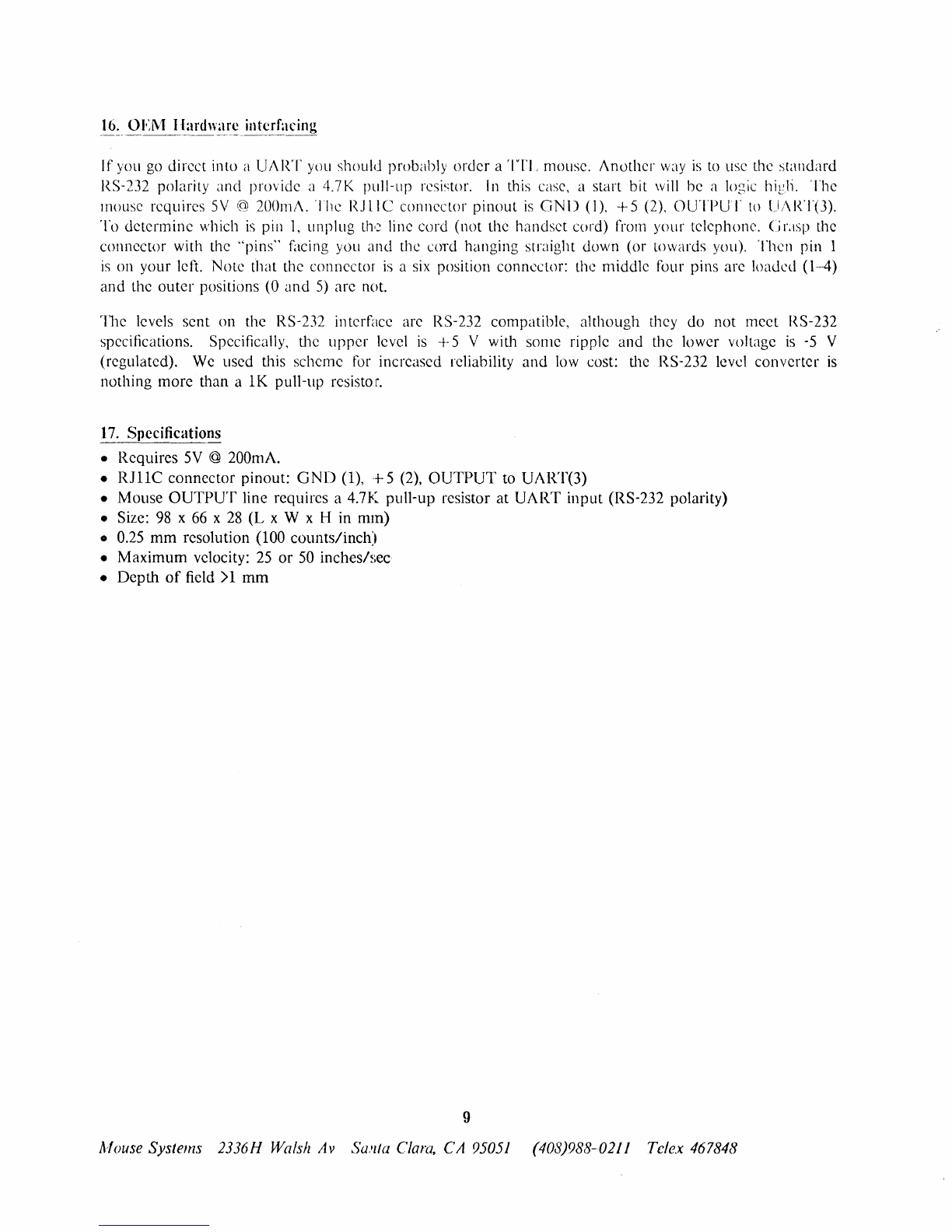
If you
go
direct into a UART yuu should probably order a
'ITI,
mOllse.
Another
way
is
to
use the standard
RS-232 polarity and provide a 4.7K pull-up resistor.
[n
this case, a start bit
will
be a logic high. The
mouse requires
5V
(gl
200111A.
The
RJlIC
connector pinout
is
GND
(1),
+5
(2),
OUTPUT
to
();\RT(3).
To determine which
is
pill
1,
unplug
th<:~
line cord (not the handset cor'd) from your telephone. C
LISp
the
connector with the "pins" facing you and the cord hanging srraight down (or towards you). Theil pin 1
is
on your left. Note that the connector
is
a
six
position connector: the middle four pins are loaded (1-4)
and the outer positions (0 and
5)
are not.
rille levels sent on the RS-
232
in
terface are RS-
232
compatible, a1though they do not meet
RS-
232
specifications. Specifically, the upper level
is
-+-
5 V with some ripple and the lower voltage
is
-5
V
(regulated).
We
used this scheme
for
increased reliability
and
low
cost: the RS-232 level converter
is
nothing more than a
lK
pull-up resisto
r.
17.
Specifications
• Requires
5V
@ 200mA.
• R1IIC connector pinout:
GND
(1),
+5 (2),
OUTPUT
to
UART(3)
• Mouse
OUTPUT
line requires a 4.7K pull-up resistor at UART input (RS-232 polarity)
• Size:
98
x
66
x
28
(L
x W x H in mm)
•
0.25
mm
resolution (100 counts/inch)
• Maximum velocity:
25
or
50
inchesh,ec
• Depth
of
field>1
mm
9
ldouse Systems 2336H Walsh Av
SWlfa
Clara,
CA
95051
(408)988-0211 Telex 467848
Table of contents


