Mouser Electronics RIoTboard MCIMX6 SOLO User manual


USER MANUAL v1.0
Date: 01/20/2014
Page | 2
Table of Contents
1
BOARD OVERVIEW........................................................................................................................... 7
1.1
P
RODUCT
I
NTRODUCTION
............................................................................................................... 7
1.2
F
EATURES
.................................................................................................................................... 8
2
HARDWARE DESCRIPTION ............................................................................................................. 11
2.1
P
ROCESSOR
............................................................................................................................... 11
2.1.1
Core Features..................................................................................................................... 11
2.1.2
External memory interfaces: .............................................................................................. 12
2.1.3
Interface to external devices .............................................................................................. 13
2.1.4
Advanced Power anagement unit................................................................................... 14
2.1.5
Hardware Accelerators ...................................................................................................... 14
2.2
E
XPANDED
C
HIP
I
NTRODUCTION
.................................................................................................... 15
2.2.1
T41K256 16HA-125:E ................................................................................................... 15
2.2.2
PF0100NPAEP.............................................................................................................. 15
2.2.3
AR8035............................................................................................................................... 15
2.2.4
FE1.1 .................................................................................................................................. 16
2.2.5
SGTL5000 ........................................................................................................................... 16
2.
E
XPANDED
C
HIP
I
NTRODUCTION
.................................................................................................... 17
2.3.1
Power Input Jack ................................................................................................................ 17
2.3.2
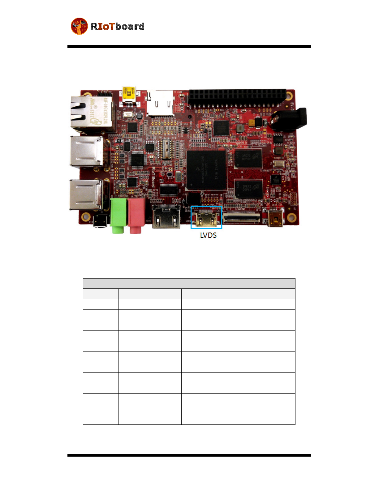
LVDS Interface.................................................................................................................... 18
2.3.3
HD I Interface................................................................................................................... 19
2.3.4
icrophone Input Jack....................................................................................................... 21
2.3.5
Audio Output Jack.............................................................................................................. 22
2.3.6
SD Card Interface ............................................................................................................... 23
2.3.7
uSD/ C Card Interface................................................................................................... 24
2.3.8
CSI Interface....................................................................................................................... 25
2.3.9
Camera Interface ............................................................................................................... 26

USER MANUAL v1.0
Date: 01/20/2014
Page |
2.3.10
JTAG Interface ................................................................................................................ 28
2.3.11
ini USB Interface ......................................................................................................... 29
2.3.12
Serial Port ...................................................................................................................... 30
2.3.13
Expansion Port Interface................................................................................................ 31
2.3.14
ini USB Interface (OpenSDA)....................................................................................... 33
2.3.15
RG II LAN Interface ...................................................................................................... 34
2.3.16
USB HUB Interface ......................................................................................................... 35
2.3.17
Boot Configuration Select .............................................................................................. 36
2.3.18
Reset Switch................................................................................................................... 38
2.3.19
LEDs ............................................................................................................................... 39
3
GETTING STARTED ......................................................................................................................... 40
.1
S
OFTWARE
F
EATURES
................................................................................................................... 40
.2
L
INUX
S
YSTEM
............................................................................................................................ 40
.
A
NDROID
S
YSTEM
....................................................................................................................... 41
.4
S
ETTING UP
T
ERMINAL
E
MULATION
................................................................................................ 42
4
DOWNLOADING AND RUNNING THE SYSTEM .............................................................................. 43
4.1
D
OWNLOAD AND
R
UN
L
INUX OR
A
NDROID
S
YSTEM
........................................................................... 43
4.2
D
ISPLAY
M
ODE
C
ONFIGURATIONS FOR
L
INUX
&
A
NDROID
S
YSTEMS
..................................................... 46
5
MAKING IMAGES ........................................................................................................................... 48
5.1
M
AKING
I
MAGES FOR
L
INUX
......................................................................................................... 48
5.1.1
Getting Tools and Source Code .......................................................................................... 48
5.1.2
Compiling System Images .................................................................................................. 48
5.2
M
AKING
I
MAGES FOR AN
A
NDROID
S
YSTEM
..................................................................................... 49
5.2.1
Getting Repo Source Code ................................................................................................. 49
5.2.2
Compiling System Images .................................................................................................. 50
6
ESD PRECAUTIONS AND PROPER HANDLING PROCEDURES......................................................... 52

USER MANUAL v1.0
Date: 01/20/2014
Page | 4
LIST OF FIGURES
Figure 1-1 Functional Block Diagram ............................................................................................... 7
Figure 1-2 RIoTboard top view ......................................................................................................... 8
Figure 1-3 RIoTboard bottom view .................................................................................................. 9
Figure 2-1 Block Diagram of i. X 6Solo......................................................................................... 12
Figure 2-2 Power Interface............................................................................................................. 17
Figure 2-3 LVDS Interface ............................................................................................................... 18
Figure 2-4 HD I Interface ............................................................................................................. 19
Figure 2-5 IC Input ...................................................................................................................... 21
Figure 2-6 Audio Output Jack ......................................................................................................... 22
Figure 2-7 SD Card Interface .......................................................................................................... 23
Figure 2-8 uSD/ C Card Interface .............................................................................................. 24
Figure 2-9 CSI Interface .................................................................................................................. 25
Figure 2-10 Camera Interface ........................................................................................................ 26
Figure 2-11 JTAG Interface ............................................................................................................. 28
Figure 2-12 ini USB Interface ...................................................................................................... 29
Figure 2-13 Serial Port ................................................................................................................... 30
Figure 2-14 Expansion Port ............................................................................................................ 31
Figure 2-15 ini USB (OpenSDA)Interface ..................................................................................... 33
Figure 2-16 RG II LAN Interface ................................................................................................... 34
Figure 2-17 USB Host Interface ...................................................................................................... 35
Figure 2-18 Boot Configuration Select ........................................................................................... 36
Figure 2-19 Reset Switch ................................................................................................................ 38
Figure 2-20 LEDs ............................................................................................................................ 39

USER MANUAL v1.0
Date: 01/20/2014
Page | 5
Figure 3-1 CO Properties ............................................................................................................. 42
Figure 4-1 Boot Configuration Switch ............................................................................................ 43
LIST OF TABLES
Table 2-1 Power Interface .............................................................................................................. 17
Table 2-2 LVDS Interface ................................................................................................................ 18
Table 2-3 HD I Interface ............................................................................................................... 19
Table 2-4 IC Input Jack ................................................................................................................ 21
Table 2-5 Audio Output Jack .......................................................................................................... 22
Table 2-6 SD Card Interface ........................................................................................................... 23
Table 2-7 uSD/ C Card Interface ............................................................................................... 24
Table 2-8 CSI Interface ................................................................................................................... 25
Table 2-9 Camera Interface ........................................................................................................... 27
Table 2-10 JTAG Interface .............................................................................................................. 28
Table 2-11 ini USB Interface ....................................................................................................... 29
Table 2-12 Serial Port ..................................................................................................................... 30
Table 2-13 Expansion Port Interface .............................................................................................. 31
Table 2-14 ini USB (OpenSDA) Interface ..................................................................................... 33
Table 2-15 RG II LAN interface ..................................................................................................... 34
Table 2-16 USB Host Interface ....................................................................................................... 35
Table 2-17 Boot Configuration Select ............................................................................................ 37
Table 2-18 Reset Switch ................................................................................................................. 38
Table 2-19 LEDs .............................................................................................................................. 39
Table 3-1 OS and Drivers ................................................................................................................ 40
Table 3-2 Images Required by Linux ............................................................................................... 40

USER MANUAL v1.0
Date: 01/20/2014
Page | 6
Table 3-3 Storage Partitions for Linux ............................................................................................ 41
Table 3-4 Images Required by Android .......................................................................................... 41
Table 3-5 Storage Partitions for Android........................................................................................ 41
Table 4-1 Boot Switch Configuration – Serial Download ................................................................ 43
Table 4-2 Boot Switch Configuration - e C ................................................................................ 46
Table 4-3 Boot Switch Configuration – SD ..................................................................................... 46
Table 5-1 Images and Directories .................................................................................................. 51
USER MANUAL v1.0
Date: 01/20/2014
Page | 7
1Boar Overview
1.1 Product Introduction
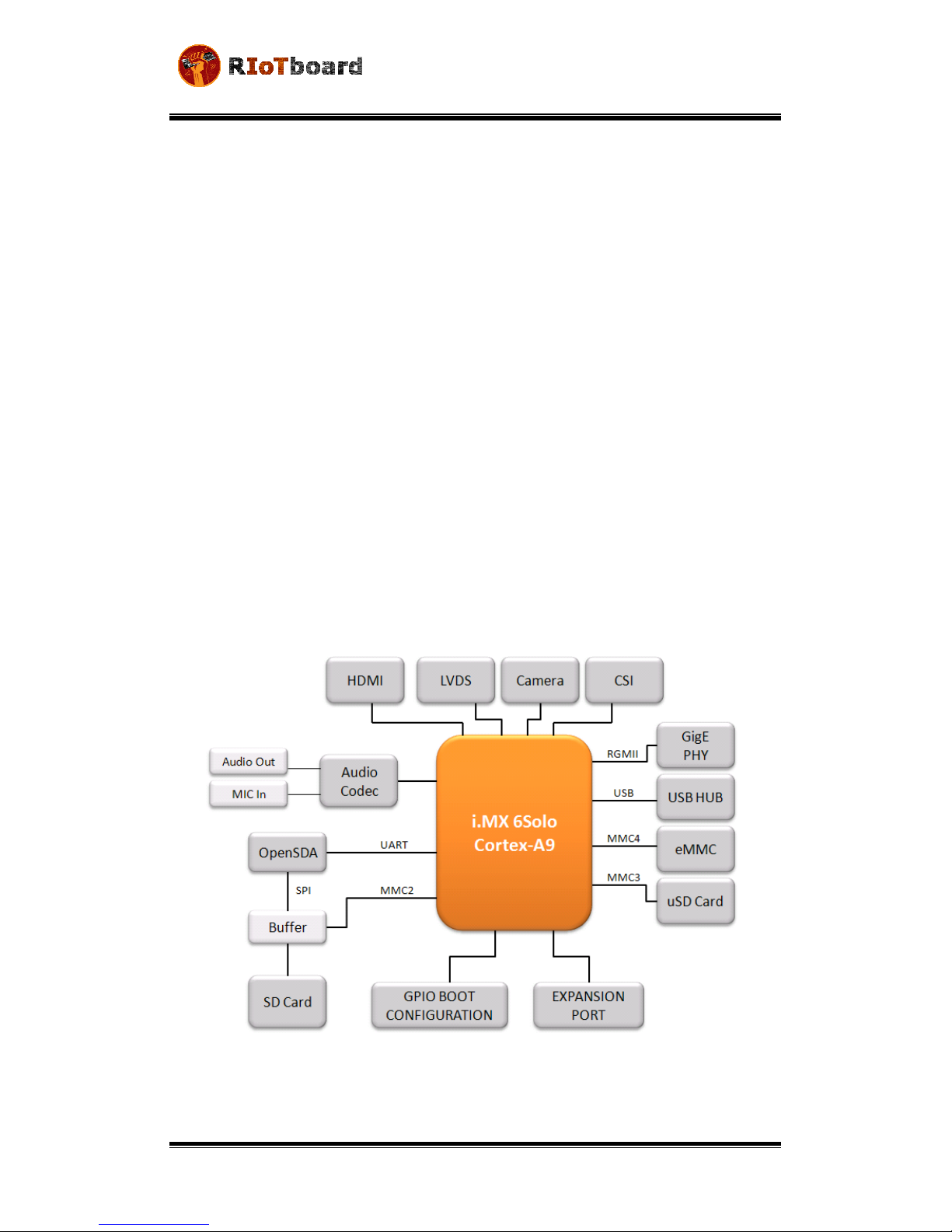
The RIoTboard is an evaluation platform featuring the powerful i.MX 6Solo, a
multimedia application processor with ARM Cortex-A9 core at 1 GHz from Freescale
Semiconductor. The platform helps evaluate the rich set of peripherals and includes
a 10/100/Gb Ethernet port, HDMI v1.4, LVDS, analog headphone/microphone, uSD
and SD card interface, USB, serial port, JTAG, 2 camera interfaces, GPIO boot
configuration interface, and expansion port, as shown in Figure 1-1.
The RIoTboard can be used in the following applications:
•Netbooks (web tablets)
•Nettops (Internet desktop devices)
•High-end mobile Internet devices (MID)
•High-end PDAs
•High-end portable media players (PMP) with HD video capability
•Portable navigation devices (PNDs)
•Industrial control and Test and measurement (T&M)
•Single board computers (SBCs)
Figure 1-1 Functional Block Diagram
USER MANUAL v1.0
Date: 01/20/2014
Page | 8
1.2 Features
The RIoTboard is based on the i.MX 6Solo processor from Freescale Semiconductor
integrating all the functionalities of this multimedia application processor with the
following features:
•Mechanical Parameters
oWorking Temperature: 0°C - 50°C
oHumidity Range: 20% - 90%
oDimensions: 120mm x 75mm
oInput Voltage: +5V
•Processor
oARM Cortex A9 MPCore™ Processor at 1 GHz
oHigh-performing video processing unit which covers SD-level and HD-
level video decoders and SD-level encoders as a multi-standard video
codec engine
oAn OpenGL® ES 2.0 D graphics accelerator with a shader and a 2D
graphics accelerator for superior D, 2D, and user interface
acceleration
•Memories
o1GByte of 16-bit wide DDR @ 800MHz
o4GB eMMC
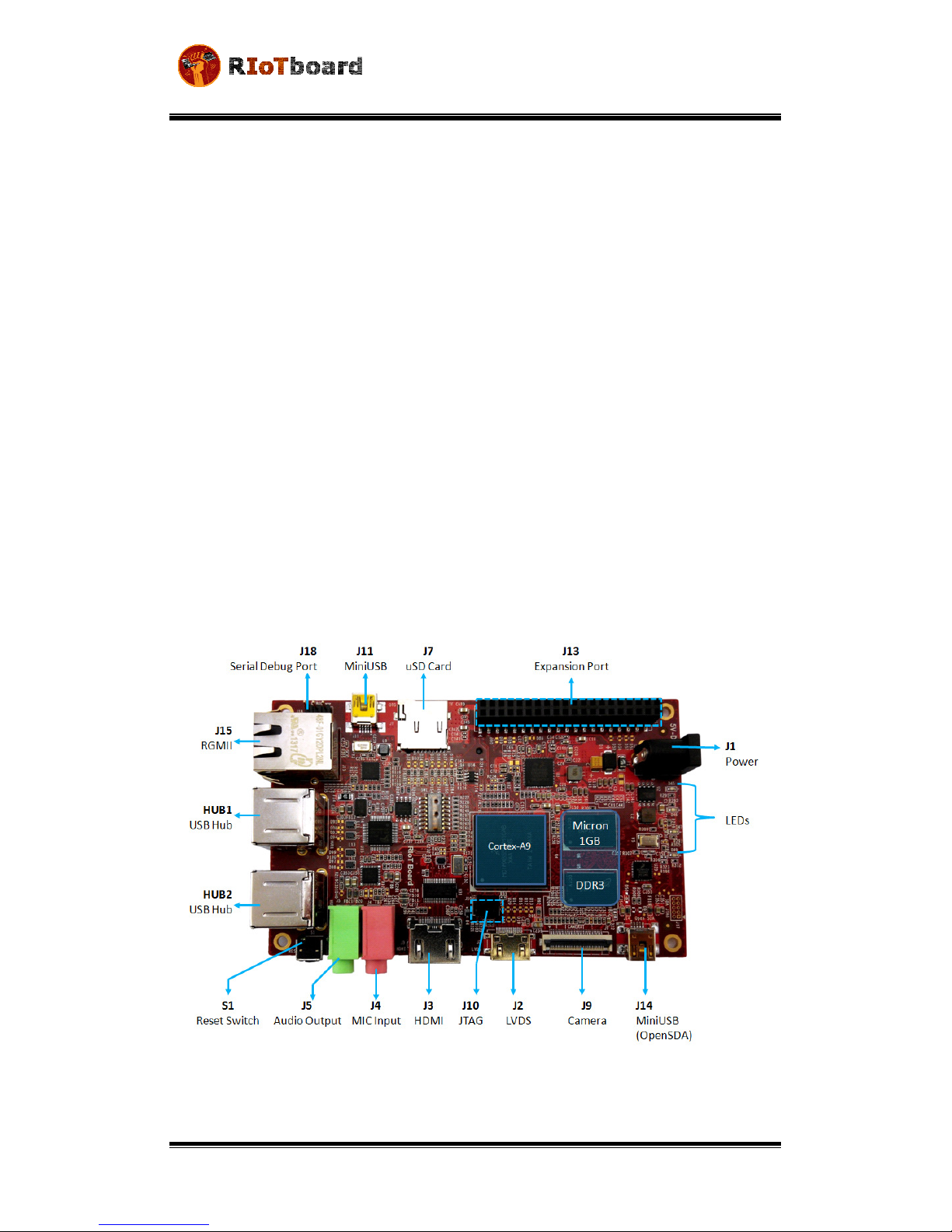
Figure 1-2 RIoTboard top view
USER MANUAL v1.0
Date: 01/20/2014
Page | 9
•Media Interfaces
oAnalog headphone/microphone, .5mm audio jack
oLVDS interface
oHDMI interface
oParallel RGB interface(Expansion port)
oCamera interface (Support CCD or CMOS camera)
oMIPI lanes at 1 Gbps
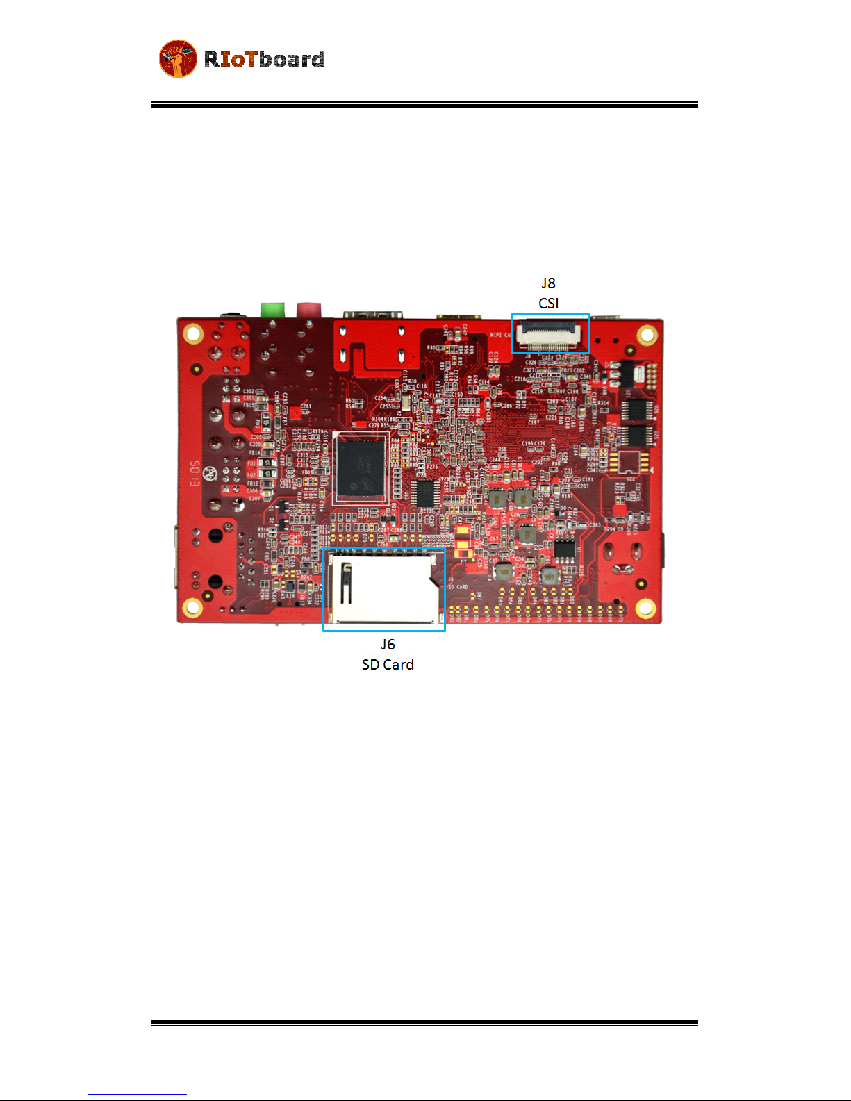
Figure 1-3 RIoTboard bottom view
•Data Transfer Interfaces
oDebug Ports:
pin TTL level
oSerial Ports:
UART ,4,5, line serial port, TTL Logic (Expansion port)
oUSB Ports:
1 x USB2.0 OTG, mini USB, high-speed, 480Mbps
4 x USB2.0 HOST, Type A, high-speed, 480Mbps
ouSD card interface
oSD card interface
o10M/100M/Gb Ethernet Interface (RJ45 jack)

USER MANUAL v1.0
Date: 01/20/2014
Page | 10
o2 channel I2C interface (Expansion port)
o2 channel SPI interface (Expansion port)
o channel PWM interface (Expansion port)
oGPIO (Expansion port)
o10-pin JTAG interface
oOpen SDA
•Others
o1 Power LED
o1 Open SDA LED
o2 User-defined LEDs
o1 DC Jack
o1 Reset button
oBoot configuration interface

USER MANUAL v1.0
Date: 01/20/2014
Page | 11
2Har ware Description
2.1 Processor
The i.MX 6Solo processor represents Freescale Semiconductor’s latest achievement in
integrated multimedia applications processors, which are part of a growing family of
multimedia-focused products that offer high performance processing and are
optimized for lowest power consumption.
The processor features Freescale’s advanced implementation of the single ARM™
Cortex-A9 core, which operates at speeds up to 1 GHz. It includes 2D and D graphics
processors, D 1080p video processing, and integrated power management. The
processor provides a 16/ 2-bit DDR /LVDDR -800 memory interface and a number of
other interfaces for connecting peripherals, such as WLAN, Bluetooth™, GPS, hard drive,
displays, and camera sensors.
2.1.1 Core Features
The i.MX 6Solo processor is based on the ARM Cortex A9 MPCore™ platform with the
following features:
•ARM Cortex A9 MPCore™ CPU Processor (with TrustZone)
•The core configuration is symmetric, where the core includes:
o2 KByte L1 Instruction Cache
o2 KByte L1 Data Cache
oPrivate Timer and Watchdog
oCortex-A9 NEON MPE (Media Processing Engine) Co-processor
•The ARM Cortex A9 MPCore™ complex includes:
oGeneral Interrupt Controller (GIC) with 128 interrupt support
oGlobal Timer
oSnoop Control Unit (SCU)
o512 KB unified I/D L2 cache
oTwo Master AXI (64-bit) bus interfaces output of L2 cache
oNEON MPE coprocessor
SIMD Media Processing Architecture
NEON register file with 2x64-bit general-purpose registers
NEON Integer execute pipeline (ALU, Shift, MAC)
NEON dual, single-precision floating point execute pipeline
(FADD, FMUL)
NEON load/store and permute pipeline
•The memory system consists of the following components:
oLevel 1 Cache-- 2 KB Instruction, 2 KB Data cache per core

USER MANUAL v1.0
Date: 01/20/2014
Page | 12
oLevel 2 Cache--Unified instruction and data (512 KByte)
oOn-Chip Memory:
Boot ROM, including HAB (96 KB)
Internal multimedia / shared, fast access RAM (OCRAM, 128 KB)
Secure/non-secure RAM (16 KB)
Figure 2-1
Block Diagram of i.MX 6Solo
2.1.2 External memory interfaces:
•16/ 2-bit LP-DDR2-800, 16/ 2-bit DDR -800 and LV-DDR -800.
•8-bit NAND-Flash, including support for Raw MLC/SLC, 2 KB, 4 KB, and 8 KB
page size, BA-NAND, PBA-NAND, LBA-NAND, OneNAND™ and others. BCH ECC
up to 40 bit.
•16/ 2-bit NOR Flash. All WEIMv2 pin are muxed on other interfaces.
•16/ 2-bit PSRAM, Cellular RAM

USER MANUAL v1.0
Date: 01/20/2014
Page | 1
2.1.3 Interface to external evices
Each i.MX 6Solo processor enables the following interfaces to external devices
(some of them are muxed and not available simultaneously):
•Displays--Total five interfaces available. Total raw pixel rate of all interfaces is
up to 450 Mpixels/sec, 24 bpp. Up to two interfaces may be active in parallel.
oOne Parallel 24-bit display port, up to 225 Mpixes/sec (for example,
WUXGA at 60 Hz or dual HD1080 and WXGA at 60 Hz)
oLVDS serial ports
:
One port up to 165 Mpixels/sec or two ports up to
85 MP/sec (for example, WUXGA at 60 Hz) each
oHDMI 1.4 port
oMIPI/DSI, two lanes at 1 Gbps
oEPDC, Color, and monochrome E-INK, up to 1650x2 2 resolution and
5-bit grayscale
•Camera sensors:
oTwo parallel Camera ports (up to 20 bit and up to 240 MHz peak)
oMIPI CSI-2 serial camera port, supporting from 80 Mbps to 1 Gbps
speed per data lane. The CSI-2 Receiver core can manage one clock
lane and up to two data lanes. Each i.MX 6Solo processor has two
lanes.
•Expansion cards:
oFour MMC/SD/SDIO card ports all supporting:
1-bit or 4-bit transfer mode specifications for SD and SDIO
cards up to UHS-I SDR-104 mode (104 MB/s max)
1-bit, 4-bit, or 8-bit transfer mode specifications for MMC cards
up to 52 MHz in both SDR and DDR modes (104 MB/s max)
•USB
oOne high speed (HS) USB 2.0 OTG (Up to 480 Mbps), with integrated HS
USB PHY
oThree USB 2.0 (480 Mbps) hosts
One HS host with integrated High Speed PHY
Two HS hosts with integrated HS-IC USB (High Speed Inter-Chip
USB) PHY
•Expansion PCI Express port (PCIe) v2.0 one lane
oPCI Express (Gen 2.0) dual mode complex, supporting Root complex
operations and Endpoint operations. Uses x1 PHY configuration.
•Miscellaneous IPs and interfaces:
oThree I2S/SSI/AC97,up to 1.4 Mbps each
oEnhanced Serial Audio Interface ESAI), up to 1.4 Mbps per channel
oFive UARTs, up to 4.0 Mbps each
Providing RS2 2 interface
Supporting 9-bit RS485 multidrop mode

USER MANUAL v1.0
Date: 01/20/2014
Page | 14
One of the five UARTs (UART1) supports 8-wire while the other
four support 4-wire. This is due to the SoC IOMUX limitation,
since all UART IPs are identical
oFour eCSPI (Enhanced CSI)
oFour I2C, supporting 400 kbps
oGigabit Ethernet Controller(IEEE1588 compliant), 10/100/1000 Mbps
oFour Pulse Width Modulators (PWM)
oSystem JTAG Controller (SJC)
oGPIO with interrupt capabilities
o8x8 Key Pad Port (KPP)
oSony Philips Digital Interface (SPDIF), Rx and Tx
oTwo Controller Area Network (FlexCAN), 1 Mbps each
oTwo Watchdog timers (WDOG)
oAudio MUX (AUDMUX)
oMLB (MediaLB) provides interface to MOST Networks (MOST25, MOST50,
MOST150) with the option of DTCP cipher accelerator
2.1.4 A vance Power Management unit
The i.MX 6Solo processors integrate advanced power management unit and
controllers:
•Provide PMU, including LDO supplies, for on-chip resources
•Use Temperature Sensor for monitoring the die temperature
•Support DVFS techniques for low power modes
•Use SW State Retention and Power Gating for ARM and MPE
•Support various levels of system power modes
•Use flexible clock gating control scheme
2.1.5 Har ware Accelerators
The i.MX 6Solo processor uses dedicated hardware accelerators to meet the targeted
multimedia performance. The use of hardware accelerators is a key factor in obtaining
high performance at low power consumption numbers, while having the CPU core
relatively free for performing other tasks.
The i.MX 6Solo processor incorporates the following hardware accelerators:
•VPU--Video Processing Unit
•IPUv H--Image Processing Unit version H
•GPU Dv5-- D Graphics Processing Unit (OpenGL ES 2.0) version 5
•GPU2Dv2--2D Graphics Processing Unit (BitBlt)
•ASRC--Asynchronous Sample Rate Converter

USER MANUAL v1.0
Date: 01/20/2014
Page | 15
Security functions are enabled and accelerated by the following hardware:
•ARM TrustZone including the TZ architecture (separation of interrupts, memory
mapping, etc.)
•SJC--System JTAG Controller. Protecting JTAG from debug port attacks by
regulating or blocking the access to the system debug features.
•CAAM--Cryptographic Acceleration and Assurance Module, containing
cryptographic and hash engines, 16 KB secure RAM and True and Pseudo
Random Number Generator (NIST certified)
•SNVS--Secure Non-Volatile Storage, including Secure Real Time Clock
•CSU--Central Security Unit. Enhancement for the IC Identification Module (IIM).
Will be configured during boot and by eFUSEs and will determine the security
level operation mode as well as the TZ policy.
•A-HAB Advanced High Assurance Boot--Hv4 with the new embedded
enhancements:SHA-256, 2048-bit RSA key, version control mechanism, warm
boot, CSU, and TZ initialization.
2.2 Expanded Chip Introduction
2.2.1 MT41K256M16HA-125:E
The board has 1GB of SDRAM (2x512MB). Micron’s MT41K256M16 is a 512MB DDR
Synchronous DRAM, ideally suited for the main memory applications which require
large memory density and high bandwidth.
2.2.2 MMPF0100NPAEP
The PF0100 Power Management Integrated Circuit (PMIC) provides a highly
programmable/ configurable architecture, with fully integrated power devices and
minimal external components. With up to six buck converters, six linear regulators, RTC
supply, and coin-cell charger, the PF0100 can provide power for a complete system,
including applications processors, memory, and system peripherals, in a wide range of
applications. With on-chip One Time Programmable (OTP) memory, the PF0100 is
available in pre-programmed standard versions, or non-programmed to support
custom programming. The PF0100 is defined to power the entire embedded MCU
platform solution similar to i.MX6 based eReader, IPTV, medical monitoring and
home/factory automation.
2.2.3 AR8035
AR80 5 is a single port 10/100/1000 Mbps tri-speed Ethernet PHY feaured with low
power and low cost. AR80 5 supports MAC.TM RGMII interface and IEEE 802. az-2010,
Energy Efficient Ethernet (EEE) standard through proprietary SmartEEE technology,
improving energy efficiency in systems using legacy MAC devices without 802. az

USER MANUAL v1.0
Date: 01/20/2014
Page | 16
support. The RIOT Board can be connected to a network hub directly through a cable. It
also can be directly connected with a computer through a crossover cable which is
provided with the kit.
2.2.4 FE1.1
FE1.1 is a USB 2.0 high-speed 4-port hub solution. It uses USB 20 to provide 4
extended USB interface with support for high-speed (480MHz), full-speed (2MHz) and
low-speed (1.5MHz) mode.
2.2.5 SGTL5000
The SGTL5000 is a low power stereo Codec with Headphone Amp from Freescale, and is
designed to provide a complete audio solution for portable products needing line-in,
mic-in, line-out, headphone-out, and digital I/O. Deriving its architecture from best-in-
class Freescale-integrated products currently on the market, the SGTL5000 is able to
achieve ultra low-power with very high performance and functionality, all in one of the
smallest footprints available.
Designed with features such as capless headphone and an integrated PLL to allow clock
reuse within the system, it helps customers achieve a lower overall system cost.
USER MANUAL v1.0
Date: 01/20/2014
Page | 17
2.3 Expanded Chip Introduction
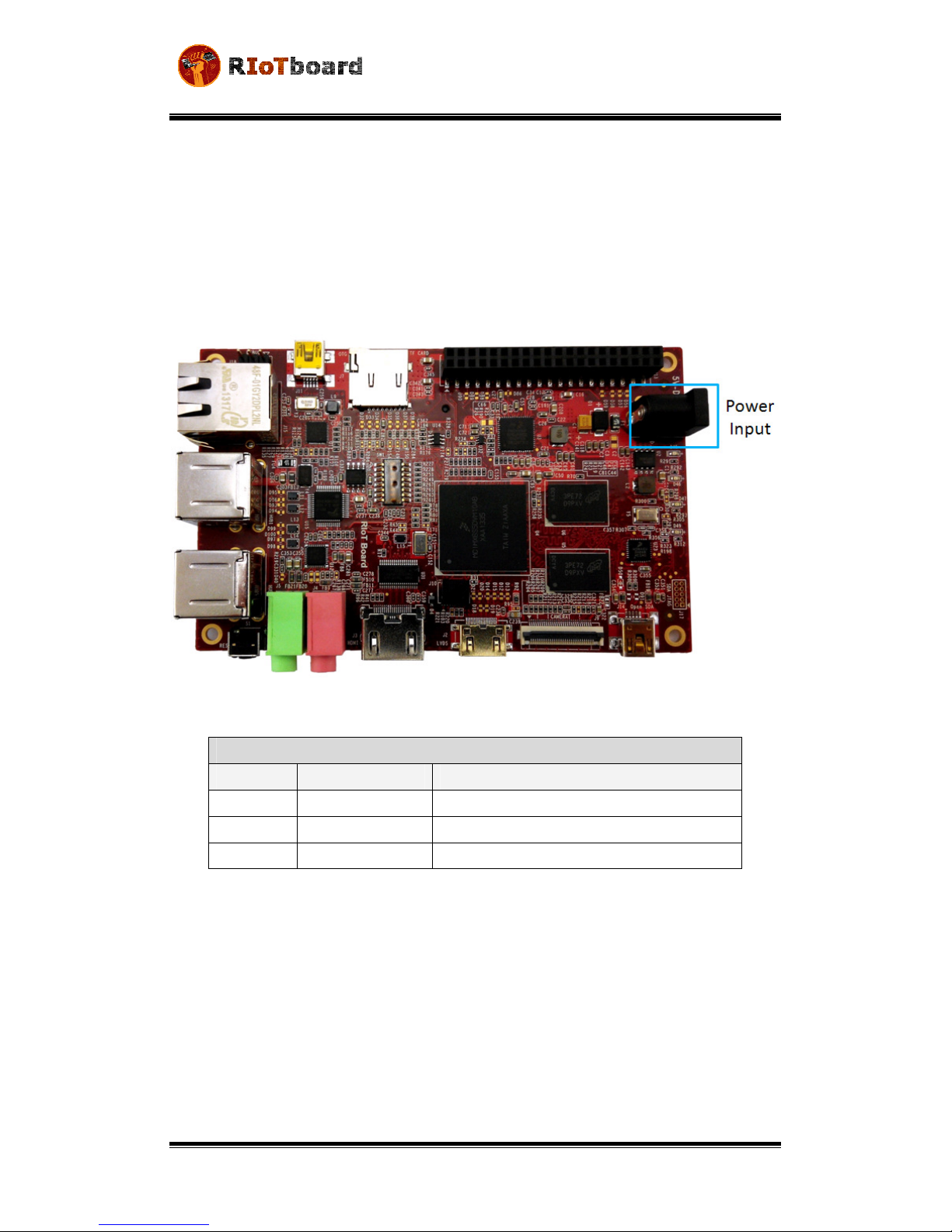
2.3.1 Power Input Jack
A 5V/4A AC-to-DC power supply needs to be plugged into the Power Jack (J1) on the
board. It is not recommended to use a higher voltage since possible damage to the
board may result due to failure of the protection circuitry.
Figure 2-2
Power Interface
Table 2-1
Power Interface
J1
Pin
Signal
Function
1
GND
GND
2
NC
NC
+5V
Power supply (+5V)
4
A (Type)
USER MANUAL v1.0
Date: 01/20/2014
Page | 18
2.3.2 LVDS Interface
Figure 2-3
LVDS Interface
The LVDS Interface supports LVDS8000-97C designed by Embest.
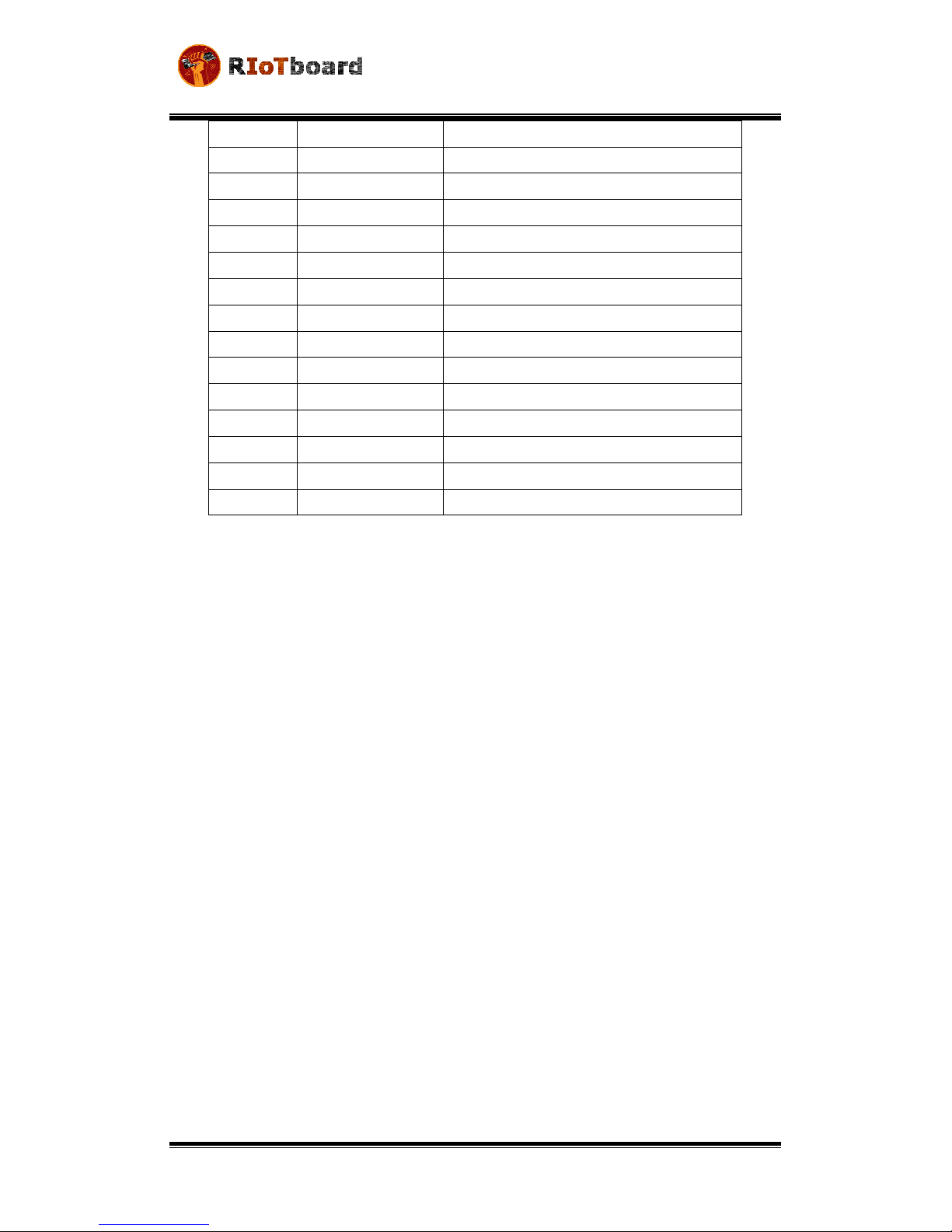
Table 2-2 LVDS Interface
J
2
Pin
Signal
Function
1
V
+
.
V
2
LV
DS_TX2_P
LVDS
d
ata
2+
LVDS_TX2_N
LVDS
d
ata
2
-
4
GND
GND
5
LVDS_TX1_P
LVDS
d
ata
1+
6
LVDS_TX1_N
LVDS
d
ata
1
-
7
GND
GND
8
LVDS_TX0_P
LVDS
d
ata
0+
9
LVDS_TX0_
N
LVDS
d
ata
-
10
GND
GND
11
LVDS_CLK_P
LVDS
CLK
+
12
LVDS_CLK_
N
LVDS
CLK
-

USER MANUAL v1.0
Date: 01/20/2014
Page | 19
1
LCD_PWR_EN
Touch
r
eset
s
ignal
14
Touch_Int
Touch
i
nterrupt
s
ignal
15
I2C_SCL
IIC
m
aster
s
erial
c
lock
16
I2C_SDA
IIC
m
aster
s
erial
d
ata
17
LED_PWR_EN
Backlight
e
nable
18
5V
+5V
19
PWM
Pulse Width Modulation
2.3.3 HDMI Interface
Figure 2-4 HDMI Interface
Table 2-3 HDMI Interface
J
Pin Signal Function
1 HDMI_D2P HDMI differential pairs data2+
2 GND GND
HDMI_D2M HDMI differential pairs data2-
4 HDMI_D1P HDMI differential pairs data1+
5 GND GND
USER MANUAL v1.0
Date: 01/20/2014
Page | 20
6
HDMI_D1M
HDMI differential pairs data1
-
7
HDMI_D0P
HDMI differential pairs data0+
8
GND
GND
9
HDMI_D0M
HDMI differential pairs data0
-
10
HDMI_CLKP
HDMI differential pairs clock+
11
GND
GND
12
HDMI_CLKM
HDMI differential pairs
clock
-
1
NC
NC
14
NC
NC
15
BI2C2_SCL
IIC2 serial clock
16
BI2C2_SDA
IIC2 serial data
17
GND
GND
18
5Vin
5V
19
HDMI_HPD
HDMI detect
20
GNF_DVI
GND
Table of contents


