Movincool 15SF User manual

SERVICE MANUAL
15SF
DocID: 00G00092E

© 2014 DENSO AUTOMOTIVE SYSTEMS AUSTRALIA PTY. LTD.
All rights reserved. This book may not be reproduced or copied, in
whole or in part, without the written permission of the publisher. DENSO
AUTOMOTIVE SYSTEMS AUSTRALIA PTY. LTD. reserves the right to
make changes without prior notice. MovinCool® is a registered
trademark of DENSO Corporation.

Table of Contents
Table of Contents
Operation Section
1. PRECAUTIONS FOR SAFETY
1.1 Foreword. . . . . . . . . . . . . . . . . . . . . . . . . . . . . . . . . . . . . . . . . . . . . . . . . . . . . . . . . . . . . . . . . . . . . . . 5
1.2 Definition of Terms . . . . . . . . . . . . . . . . . . . . . . . . . . . . . . . . . . . . . . . . . . . . . . . . . . . . . . . . . . . . . . . 5
1.3 General Precautions . . . . . . . . . . . . . . . . . . . . . . . . . . . . . . . . . . . . . . . . . . . . . . . . . . . . . . . . . . . . . . 6
2. SPECIFICATIONS
2.1 Exterior Dimension Diagram. . . . . . . . . . . . . . . . . . . . . . . . . . . . . . . . . . . . . . . . . . . . . . . . . . . . . . . . 7
2.2 Technical Specifications . . . . . . . . . . . . . . . . . . . . . . . . . . . . . . . . . . . . . . . . . . . . . . . . . . . . . . . . . . . 8
2.3 Characteristics . . . . . . . . . . . . . . . . . . . . . . . . . . . . . . . . . . . . . . . . . . . . . . . . . . . . . . . . . . . . . . . . . 10
3. CONSTRUCTION
3.1 Internal Structure . . . . . . . . . . . . . . . . . . . . . . . . . . . . . . . . . . . . . . . . . . . . . . . . . . . . . . . . . . . . . . . 12
4. REFRIGERATION SYSTEM
4.1 Refrigeration System Construction . . . . . . . . . . . . . . . . . . . . . . . . . . . . . . . . . . . . . . . . . . . . . . . . . . 13
4.2 Compressor . . . . . . . . . . . . . . . . . . . . . . . . . . . . . . . . . . . . . . . . . . . . . . . . . . . . . . . . . . . . . . . . . . . 14
4.3 Condenser . . . . . . . . . . . . . . . . . . . . . . . . . . . . . . . . . . . . . . . . . . . . . . . . . . . . . . . . . . . . . . . . . . . . 17
4.4 Capillary Tube. . . . . . . . . . . . . . . . . . . . . . . . . . . . . . . . . . . . . . . . . . . . . . . . . . . . . . . . . . . . . . . . . . 18
4.5 Evaporator . . . . . . . . . . . . . . . . . . . . . . . . . . . . . . . . . . . . . . . . . . . . . . . . . . . . . . . . . . . . . . . . . . . . 18
4.6 Accumulator . . . . . . . . . . . . . . . . . . . . . . . . . . . . . . . . . . . . . . . . . . . . . . . . . . . . . . . . . . . . . . . . . . . 18
5. ELECTRICAL SYSTEM
5.1 Circuit Diagram . . . . . . . . . . . . . . . . . . . . . . . . . . . . . . . . . . . . . . . . . . . . . . . . . . . . . . . . . . . . . . . . . 19
5.2 Control Box . . . . . . . . . . . . . . . . . . . . . . . . . . . . . . . . . . . . . . . . . . . . . . . . . . . . . . . . . . . . . . . . . . . . 20
5.3 Control Specifications . . . . . . . . . . . . . . . . . . . . . . . . . . . . . . . . . . . . . . . . . . . . . . . . . . . . . . . . . . . . 24
5.4 Compressor . . . . . . . . . . . . . . . . . . . . . . . . . . . . . . . . . . . . . . . . . . . . . . . . . . . . . . . . . . . . . . . . . . . 27
5.5 Fan Motor . . . . . . . . . . . . . . . . . . . . . . . . . . . . . . . . . . . . . . . . . . . . . . . . . . . . . . . . . . . . . . . . . . . . . 28
5.6 Temperature Thermistor . . . . . . . . . . . . . . . . . . . . . . . . . . . . . . . . . . . . . . . . . . . . . . . . . . . . . . . . . . 28
5.7 Drain Tank Switch . . . . . . . . . . . . . . . . . . . . . . . . . . . . . . . . . . . . . . . . . . . . . . . . . . . . . . . . . . . . . . . 29
6. OPERATION
6.1 Operation of Control Panel . . . . . . . . . . . . . . . . . . . . . . . . . . . . . . . . . . . . . . . . . . . . . . . . . . . . . . . . 30

Table of Contents
Repair Section
7. TROUBLESHOOTING
7.1 Troubleshooting . . . . . . . . . . . . . . . . . . . . . . . . . . . . . . . . . . . . . . . . . . . . . . . . . . . . . . . . . . . . . . . . 32
7.2 Self-Diagnostic Codes . . . . . . . . . . . . . . . . . . . . . . . . . . . . . . . . . . . . . . . . . . . . . . . . . . . . . . . . . . . 33
7.3 Troubleshooting Chart . . . . . . . . . . . . . . . . . . . . . . . . . . . . . . . . . . . . . . . . . . . . . . . . . . . . . . . . . . . 34
7.4 Basic Inspection . . . . . . . . . . . . . . . . . . . . . . . . . . . . . . . . . . . . . . . . . . . . . . . . . . . . . . . . . . . . . . . . 38
7.5 Compressor Inspection. . . . . . . . . . . . . . . . . . . . . . . . . . . . . . . . . . . . . . . . . . . . . . . . . . . . . . . . . . . 39
7.6 Fan Motor Inspection . . . . . . . . . . . . . . . . . . . . . . . . . . . . . . . . . . . . . . . . . . . . . . . . . . . . . . . . . . . . 39
7.7 Capacitor Inspection (For Fan Motor and Compressor) . . . . . . . . . . . . . . . . . . . . . . . . . . . . . . . . . . 40
7.8 Auxiliary Relay Inspection. . . . . . . . . . . . . . . . . . . . . . . . . . . . . . . . . . . . . . . . . . . . . . . . . . . . . . . . . 41
7.9 Full Drain Switch Inspection . . . . . . . . . . . . . . . . . . . . . . . . . . . . . . . . . . . . . . . . . . . . . . . . . . . . . . . 41
7.10 Thermistor Inspection . . . . . . . . . . . . . . . . . . . . . . . . . . . . . . . . . . . . . . . . . . . . . . . . . . . . . . . . . . . . 41
7.11 Wiring Connection Inspection . . . . . . . . . . . . . . . . . . . . . . . . . . . . . . . . . . . . . . . . . . . . . . . . . . . . . . 42
7.12 Inspection of Refrigeration System. . . . . . . . . . . . . . . . . . . . . . . . . . . . . . . . . . . . . . . . . . . . . . . . . . 42
8. DISASSEMBLY
8.1 Parts Construction . . . . . . . . . . . . . . . . . . . . . . . . . . . . . . . . . . . . . . . . . . . . . . . . . . . . . . . . . . . . . . 43
8.2 Disassembly . . . . . . . . . . . . . . . . . . . . . . . . . . . . . . . . . . . . . . . . . . . . . . . . . . . . . . . . . . . . . . . . . . . 44
8.3 Fan Motor Removal . . . . . . . . . . . . . . . . . . . . . . . . . . . . . . . . . . . . . . . . . . . . . . . . . . . . . . . . . . . . . 47
8.4 Removal of Electrical Components. . . . . . . . . . . . . . . . . . . . . . . . . . . . . . . . . . . . . . . . . . . . . . . . . . 50
8.5 Full Drain Switch Removal . . . . . . . . . . . . . . . . . . . . . . . . . . . . . . . . . . . . . . . . . . . . . . . . . . . . . . . . 54
9. REFRIGERATION SYSTEM REPAIR
9.1 Repair of Refrigeration System. . . . . . . . . . . . . . . . . . . . . . . . . . . . . . . . . . . . . . . . . . . . . . . . . . . . . 55
9.2 Removal of Refrigeration System Components . . . . . . . . . . . . . . . . . . . . . . . . . . . . . . . . . . . . . . . . 57
9.3 Preparing the System for Charging with R-410A Refrigerant . . . . . . . . . . . . . . . . . . . . . . . . . . . . . . 58
9.4 Refrigerant Charging Work . . . . . . . . . . . . . . . . . . . . . . . . . . . . . . . . . . . . . . . . . . . . . . . . . . . . . . . . 60
10. REASSEMBLY
10.1 Reassembly of Unit. . . . . . . . . . . . . . . . . . . . . . . . . . . . . . . . . . . . . . . . . . . . . . . . . . . . . . . . . . . . . . 62
10.2 Compressor Installation . . . . . . . . . . . . . . . . . . . . . . . . . . . . . . . . . . . . . . . . . . . . . . . . . . . . . . . . . . 62
10.3 Fan Assembly . . . . . . . . . . . . . . . . . . . . . . . . . . . . . . . . . . . . . . . . . . . . . . . . . . . . . . . . . . . . . . . . . . 63
10.4 Wiring Notice . . . . . . . . . . . . . . . . . . . . . . . . . . . . . . . . . . . . . . . . . . . . . . . . . . . . . . . . . . . . . . . . . . 63
10.5 Perform an Inspection. . . . . . . . . . . . . . . . . . . . . . . . . . . . . . . . . . . . . . . . . . . . . . . . . . . . . . . . . . . . 63

Operation Section 5
1. PRECAUTIONS FOR SAFETY
1.1 Foreword
• This manual has been published to service the MovinCool 15SF.
Please use this service manual only when servicing the 15SF.
• Please forward these instructions to subsequent owners of your MovinCool 15SF.
• Refer to the 15SF spare parts catalogue for spare parts ordering information.
1.2 Definition of Terms
Describes precautions that should be observed in order to prevent injury to
the user during installation or unit operation.
Describes precautions that should be observed in order to prevent damage to
the unit or its components, which may occur during installation or unit
operation if sufficient care is not taken.
NOTE Provides additional information that facilitates installation or unit operation.
WARNING
CAUTION

Operation Section
6
1.3 General Precautions
WARNING
• All electrical work should only be performed by qualified electrical personnel. Repair to
electrical components by non-certified technicians may result in personal injury and/or
damage to the unit. All electrical components replaced must be genuine MovinCool parts,
purchased from an authorized reseller.
• This air conditioner uses R-410A refrigerant under high pressure. It is both dangerous
and illegal to tamper with the sealed refrigerant system without appropriate licensing and
training. Deliberate release of refrigerant is illegal in Australia, New Zealand and other
regions.
• Refrigerant recovery and charging equipment must be specifically rated for use with R-
410A.
• Observe Refrigerant Handling Code of Practice and all other applicable regulatory
requirements.
• Before replacing any refrigeration components, recover the refrigerant using standard
recovery procedures and equipment.
• When handling refrigerant, always wear proper eye protection and do not allow the
refrigerant to come in contact with your skin.
• Do not expose refrigerant to an open flame.
• The power supply for this unit should be a dedicated single outlet circuit with short-circuit
protection and residual current protective device to prevent electrical shock from the unit.
• When brazing any tubing, always wear eye protection, and work only in a well ventilated
area.
• Disconnect power before servicing this unit.
• Be careful of any sharp edges when working on this unit.

Operation Section 7
2. SPECIFICATIONS
2.1 Exterior Dimension Diagram
ILL00698-00
OBSTACLE
OBSTACLE
95 175
326
420
491
525
2100
45
672
1050
284 503 163
100
Unit: mm
DIA. 350
OBSTACLE
Minimum
clearance
500 mm
Minimum
clearance
500 mm
Minimum
clearance
500 mm

Operation Section
8
2.2 Technical Specifications
ITEM SPECIFICATIONS
Electronic Features Operation Digital Electronic
Electrical Characteristics Voltage Requirement 1 Phase, 230 V, 50 Hz
Operating Voltage
Range
Max. 254.4 V
Min. 196.6 V
Starting Current 25 A
Recommended Breaker Size 10 A
Cooling Capacity and Power Consumption
Evaporator: 35 °C, 60 %RH
Condenser: 35 °C, 60 %RH
Cooling Capacity 4.4 kW
Power Consumption 1.5 kW
Current Consumption 6.7 A
COP 2.9
Power Factor 97%
Compressor Type Hermetic Rotary
Output 0.94 kW
Evaporator Type of Evaporator Spine Fin
Type of Fan Centrifugal Fan
Air Flow 800 m3/h
Motor Output *1 0.35 kW
Condenser Type of Condenser Plate Fin
Type of Fan Centrifugal Fan
Air Flow 1500 m3/h
Motor Output *1 -
Refrigerant Refrigerant Control Capillary Tube
Type R-410A
Amount 0.75 kg
Power Cord Plug AC 250 V, 10 A
Wire Length 2.1 m
Dimension W ×D ×H 491 ×672 ×1050 mm
Weight Net 76 kg
Shipping 90 kg
Drain Tank Capacity 19 L
Operating Condition
Range
Inlet Air
Temperature
Max. 40 °C, 50 %RH
Min. 21 °C, 50 %RH
Sound Level *2 64 dB (A)

Operation Section 9
• Specifications are subject to change without notice.
< NOTE >
*1 : One motor rotates both the evaporator and the condenser fans.
*2 : Measured at 1.0 m from surface of the unit.
Safety Devices Compressor Overload Relay Included
Fan Motor Overload Relay Included
Freeze Protection Thermistor Included
Drain Warning Switch Included
Automatic Restart (Power Interruption) Included
Compressor Time Delay 120 sec
Control Devices Temperature Control Included
ITEM SPECIFICATIONS

Operation Section
10
2.3 Characteristics
(1) Cooling capacity curve
(2) Power consumption curve
ILL00720-00
2015 25 30
25
30
35
40
3.0
3.5
4.0
4.5
5.0
5.5
Cooling Capacity. kWDry Bulb Temp. °C
Wet Bulb Temp. °C
ILL00721-00
25 30 3520
25
30
35
40
1.0
1.2
1.4
1.6
1.1
1.3
1.5
1.7
1.8
Power Consumption. kWDry Bulb Temp. °C
Wet Bulb Temp. °C

Operation Section 11
(3) Cool air temperature difference curve
ILL00722-00
(Delta-T) °C
Relative Humidity. %
40 50 60 70
Temperature Difference
Between Inlet and Outlet
15
14
13
12
11
10
9
8
7

Operation Section
12
3. CONSTRUCTION
3.1 Internal Structure
ILL00723-00
Capillary Tube
Condenser
Evaporator
Compressor and
Accumulator
Condenser Fan
and Motor
Housing for
Condenser Fan Housing for
Evaporator Fan
Control Box
• Relay Board
• Capacitor
• Auxiliary Relay
Condenser Air Outlet
Cooling Air Duct
Freeze Protection
Thermistor (CTS)
Evaporator Inlet Air
Thermistor (RTS)
Drain Tank
Caster (Rear)
Full Drain Switch
Locking Swivel Caster
(Front)
Control Panel

Operation Section 13
4. REFRIGERATION SYSTEM
4.1 Refrigeration System Construction
The component parts of the refrigeration system include the following:
• Compressor, Evaporator, Condenser, Accumulator, Capillary tube
The parts above are all connected by copper piping with brazed connections.
ILL00724-00
Condenser Flow of
Refrigerant
Capillary
Tube
Compressor
Fan
Motor
Evaporator
Condenser
Condenser
Inlet Pipe
Condenser
Outlet Pipe
Connecting Pipe
(Evaporator to Compressor)
Connecting Pipe
(Condenser to Capillary Tube)
Compressor
Suction Pipe
Capillary Tube
Evaporator Inlet Pipe
Evaporator
Evaporator Outlet Pipe
Compressor
Compressor
Discharge Pipe
Accumulator
Accumulator
Operation Section
14
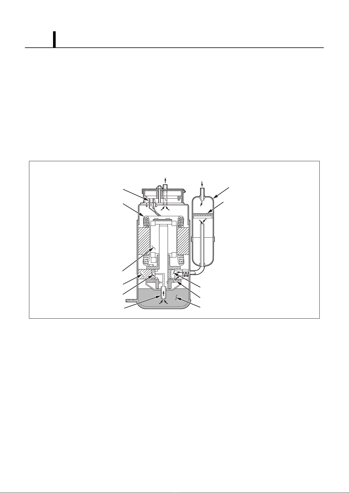
4.2 Compressor
• The compressor used for the unit is hermetically sealed. The compressor and the compressor
motor are in one casing.
(1) Compressor construction
• The construction of a rotary type compressor is divided into two mechanisms; the drive
mechanism (compressor motor), and the compression mechanism (compressor). When the
rotor shaft of the motor (drive mechanism) turns, the roller (compression mechanism) rotates to
compress the refrigerant.
I001675
To Condenser
Accumulator
Strainer
From Evaporator
Blade
Discharge Valve
Oil
Lubricator
Roller
Cylinder
Rotor
Stator
Terminal

Operation Section 15
(2) Basic compressor operation
• The roller (compression mechanism) is set
eccentrically with a certain distance given from
the axis of the center of the cylinder. A spring
loaded blade is mounted on the cylinder. The
roller turns to compress the refrigerant in the
space between the cylinder and eccentrically
mounted roller. The blade is in contact with the
roller by means of spring force. The blade
partitions the space between the suction side
and the discharge side to keep compressed refrigerant from returning to the suction side. There
is no suction valve. The discharge valve is designed not to open until the pressure of the
refrigerant within the cylinder reaches or exceeds discharge side pressure. As a result, the
discharge valve prevents the backward flow of refrigerant gas.
I000510
Discharge
Hole
Cylinder
Blade
Spring
Suction
Hole
Discharge
Valve
Shaft
Roller

Operation Section
16
(3) Operation
1) Start of compression
1) The cylinder is filled with low pressure gas.
2) Since pressure in the discharge chamber is higher
than in the cylinder, the discharge valve is kept
closed.
2) Suction and compression
1) The pressure in the cylinder increases gradually.
2) Refrigerant suction begins on the suction side of
the cylinder.
3) The discharge valve remains closed.
3) Discharge
1) The pressure in the cylinder exceeds that in the
discharge chamber, and the discharge valve
opens.
2) On the suction side, refrigerant suction continues.
4) Completion of compression
1) When compression is completed, all of the
refrigerant has been drawn from the suction
chamber.
2) Operation then returns to step 1) (Start of
compression) and the above process of suction
and compression continues repeatedly in
succession.
I001676
Blade
Discharge
Valve
Roller
I001677
Blade
Discharge
Valve
Roller
I001678
Blade
Discharge
Valve
Roller
I001679
Blade
Discharge
Valve
Roller

Operation Section 17
(4) Compressor lubrication
• The lubrication system is comprised of a
hollow shaft, an oil scraper mounted at the end
face, hollow shaft, a shaft journal (shaft
bearing), and the lubrication groove for the
shaft journal. The lubrication groove is wider
than the oil hole. When the shaft turns, oil is
scraped upward by the oil scraper along the
inside diameter of the hollow shaft. The oil is
fed through the oil hole by centrifugal force,
then supplied to the lubrication groove for each
shaft journal, lubricating the bearing. In this
lubrication system, oil enters into each bearing
separately and returns to the oil reservoir. This
system effectively prevents bearing
temperature increases, and offers high
reliability. In addition, the specially treated
shaft journal keeps the bearing from being damaged during high temperature operation.
4.3 Condenser
• The condenser is a heat exchanger with
copper tubes that are covered with thin
aluminum projections called plate fins.
• Heat is given off and absorbed by air being
pulled across the condenser fins by the
centrifugal fan and then expelled through the
exhaust air duct.
ILL00753-00
Oil Feed Groove
Oil Hole Oil Scraper
Roller
Rotor
Cylinder
Hollow Shaft Eccentric Shaft
I002351

Operation Section
18
4.4 Capillary Tube
• The capillary tube is a long thin tube that
utilizes line flow resistance as an expansion
valve. The length and the inner diameter of the
capillary tube are determined according to the
capacity of the refrigeration system, operating
conditions, and the amount of refrigerant. The
high pressure, high temperature liquid
refrigerant sent from the condenser expands
rapidly as the refrigerant is sprayed out through
the fixed orifice in the capillary tube. As a result, the temperature and state of the refrigerant
becomes low and mist-like, and therefore evaporates easily.
4.5 Evaporator
• The evaporator is a heat exchanger covered
with spine fins. Heat is removed from the air
being pulled across the evaporator by the
centrifugal fan. The resulting cool air is
expelled through the cooling air ducts.
4.6 Accumulator
• The accumulator is mounted on the suction
gas piping between the evaporator and the
compressor. The accumulator separates the
liquid refrigerant from the gas refrigerant,
allowing only the gas refrigerant to enter the
compressor. In the accumulator, suction gas is
led into a cylindrical vessel where the speed of
the gas is decreased. This process separates
the refrigerant contained in the gas by the force
of gravity, causing the refrigerant to accumulate at the bottom of the vessel. As a result, the
compressor is protected from possible damage caused by liquid refrigerant intake.
I001887
High Temp./High Pressure
Liquid Refrigerant
Low Temp./Low Pressure
Gas and Liquid Mixture
I002352
I000514
From Evaporator
To Compressor

Operation Section 19
5. ELECTRICAL SYSTEM
5.1 Circuit Diagram
ILL00725-00
AP Attachment Plug
TB
DS
Terminal Block
RB Relay Board
CB Control Board
MC Compressor Motor
MF Fan Motor
RX Auxiliary Relay
Drain Switch
RTS
CTS Freeze Protection Thermistor
Room Thermistor
OLC Overload Relay For Compressor
IOLF Internal Overload Relay For Fan Motor
OLC
MC
MF
IOLF
AC230V 1Φ 50Hz
AP
Jumper
Line
Jumper
Line
CTS RTS DS
RB
F
CB
CC Capacitor for Compressor
CF Capacitor for Fan Motor
TB2
L2
L1
1
1213
1
12
3
A1
13 14
A2
RX
CF
M
1~
M
1~
12
CC
1
t’ t’
313
4
1
5
1
5
43
CN01
CN21
CN03
CN13
CN17
5
1
CN8
1
11
CN25
11
1
CN9
CN12 CN11 CN16
52ID
52ID
52CM
52CM

Operation Section
20
5.2 Control Box
(1) Capacitor
• The capacitor is used to improve the rotational
power of the fan motor and compressor at
startup. The specification for each capacitor is
shown below.
Specifications:
Capacitor Rated Voltage Capacitance
For Fan Motor 400 V 10 µF
For Compressor 400 V 35 µF
ILL00726-00
RB: Relay Board
CF: Capacitor for Fan Motor
TB: Terminal Block
CC: Capacitor for Compressor
RX: Auxiliary Relay
CC
RX
RB
TB
CF
12
21
L2L1
CN13CN12CN11CN04CN03CN02CN14CN16CN15
CN01
CN24
4 52CM
CN17
CN25
3
ILL00561-00
Table of contents


