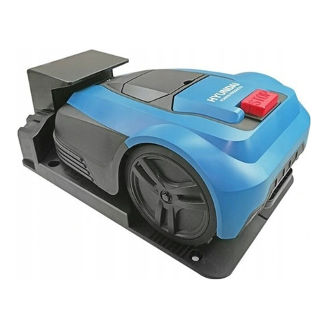
MOWBOT MOWBOT800 User manual

1
MODELS: MOWBOT800 (DYM220601)
MOWBOT1200 (DYM220602)
OWNER’S MANUAL
MowBot - Robotic Lawnmowers
Henton and Chattell Ltd., London Road, Nottingham NG2 3HW UK
www.mowbot.co.uk
Please read this manual carefully prior to assembling and operating the
Mower. It is dangerous to operate this product without being familiar with
these instructions. Keep this manual in a safe place and have it ready for
future reference.

2
Table of Contents
Chapter 1 –Safety instructions
1.1 Safe operating practice
1
1.2 The robotic mower safety features
3
1.3 Safety symbols
4
1.4 Lightning protection
5
Chapter 2 – Technical data
6
Chapter 3 – Understanding the robotic mower
7
3.1 Packaging contents
7
3.2 The robotic mower basic operating principles
8
3.3 Cutting height adjustment
8
Chapter 4 – Installation guide
9
4.1. Introduction
9
4.2 Perimeter islands
9
4.3. Boundary wire
10
4.4 Charging station
12
4.4.1 Prepare the boundary wire for the charging station
13
4.4.2 Connect the charging station with the boundary
14
4.4.3 Connecting the charging station to the charger
14
4.5 Charging information
15
4.6 Turn on and test the installation
15
4.7 Secure the charging base
15
Chapter 5 – Programming
16
5.1 Control panel
16
5.2 Main operation menu overview
17
5.3 Battery
17
5.4 Settings
18
5.5 Cutting
23
5.6 Charging
23
5.7 Change PIN code
24
5.8 Firmware update
25
5.9 Alert or note information
25
Chapter 6 – Maintenance
29
6.1 Battery life
29
6.2 Winter storage
29
6.3 Cleaning and maintenance
29
Chapter 7 – Trouble shooting
31
7.1 Troubleshooting: Charging station
31
7.2 Troubleshooting: Robotic mower
31
8. Warranty
35
9. Environmental care
35
10. EC-Declaration of Conformity2
36

1
Chapter 1- Safety Instruction
IMPORTANT
Read all safety warnings and all instructions.
Failure to follow the warnings and instructions may result in electric shock, fire and / or serious injury.
Carefully read the instructions for the safe operation of the machine. Save all warnings and instructions
for
future reference.
The Robotic Mower is to be used only for mowing the garden lawn.
Any other use is deemed to be a case of
mis
use.
WARNING: The product can be dangerous if used incorrectly
WARNING: Do not use the product when persons, especially children, or animals are in the
work area.
WARNING: Keep your hands and feet away from the rotating blades. Never put your hands or
feet close to or under the product when the motor is running.
1.1 Safe operating practice
Training
1. Read the instructions carefully, make sure you understood them fully. Be familiar with the
contr
ols and the proper
use of the machine.
2. Never allow children, persons with reduced physical, sensory or mental capabilities or lack of experience and
knowledge, or people unfamiliar with these instructions to use the machine.
3. Local regulations may restrict the age of the operator.
4. The operator or user is responsible for accidents or hazards occurring to other people or their property.
Preparation
1. Ensure the correct installation of the perimeter boundary system as instructed.
2. Periodically inspect the area where the machine is to be used and remove all stones, sticks, wires, and other
debris which could cause damage to the machine or surrounding areas.
3. Periodically visually inspect to see that the blades, blade bolts and cutter assembly are not worn or damaged.
Replace worn or damaged blades and bolts in sets to preserve balance.
4. On multi-spindle machines, take care as rotating one blade can cause other blades to rotate.
Operation
1. Do not operate the Robotic Mower if any safety feature or any part is damaged, worn out or inoperable.
2. Keep hands and feet away from the cutting blade and other moving parts.
3. Never pick up or carry the Robotic Mower while the motors are running.
4. Do not leave the Robotic Mower unattended if you know that there are pets, children or people in the vicinity.
5. Never mow while people, especially children or pets are nearby.
6. Always switch off the main power switch on the mower before lifting it up or plan to complete any adjustments.
7. Do not touch the blade before it has completely stopped rotating.

2
EN
8. Use the Robotic Mower for lawn mowing only.
9. Keep all guards, shields, safety devices, and sensors in place. Repair or replace damaged parts, including
warning labels.
Transportation
To safely move from or within the working area:
1. Press the red STOP button to stop the Robotic Mower.
2. Ensure that the main power switch is selected to OFF position before you lift up your Robotic Mower.
3. Close the top covers, and carry the Robotic Mower on the rear handle, the blade disc must be directed away from
your body.
IMPORTANT! It is recommended to keep the original packaging for shipping purposes.
IMPORTANT! After turning on the Robotic Mower, always re-set the current day and time, otherwise unexpected
operation of the Robotic Mower may occur.
Maintenance and Special Instructions
1. Always switch off the main power switch of the Robotic Mower before clearing blockages/ checking/ cleaning/
working on it or replacing the blades. Never attempt to service or adjust the Robotic Mower while it is in operation.
2. In case of abnormal vibrations, stop the mower, switch off the main power switch and check for any damage to
the blades. Replace worn or damaged blades to preserve balance. If vibration continues, contact a service
centre.
3. Use thick / heavy gloves when inspecting or servicing the blades.
4. Do not perform maintenance when barefoot or wearing open sandals. Always wear suitable work shoes and long
trousers;
5. Replace worn or damaged parts for your safety.
6. Use only original parts and accessories. It is not permitted to modify the original design of the Robotic Mower. All
modifications are made at your own risk and void the warranty.
7. Keep all nuts, bolts and screws tight to be sure the machine is in safe working condition.
8. Warning! When there is a risk of a lightning, disconnect the perimeter wire from the base station, and unplug
the transformer plug from the power source.
Batteries
1. Do not open or damage the battery pack.
2. The battery pack should be replaced only by a service dealer.
3. The battery pack contains electrolytes. In case of an electrolyte leakage from the battery pack, the following
actions must be taken:
- Skin contact: Wash off the contact areas with water and soap immediately.
- Eye contact: Flush the eyes with plenty of clean water immediately for at least 15 minutes, without rubbing.
- Seek medical advice immediately.
4. Ensure that the battery pack is charged using the correct charger recommended by the manufacturer. Incorrect
use may result in electric shock, overheating or leakage of corrosive liquid from the battery.
Charger
1. The socket-outlet should be installed near the charger station and should be easily accessible.
2. This transformer is short-circuit proof and safety-isolated.
3. The external flexible cable or cord of this unit cannot be replaced; if the cord is damaged, the unit must be
exchanged completely.
4. Do not open the charger, to avoid electrical shock. Only qualified service personnel should repair the charger.
5. Protect the charger from humidity.

3
6. Disconnect the equipment from the power supply before cleaning. Do not use any liquid or aerosol cleaner.
7. The charger should be placed on a stable surface. A drop may cause damage.
8. If the equipment is not used for a long time, disconnect it from the power supply to avoid damages from voltage
peaks or lightning strikes.
9. If one of the following situations occurs, the equipment must be checked by a qualified service personnel
- Plug is damaged.
- Liquid has penetrated into the equipment.
- Equipment has been exposed to humidity.
- Equipment has been dropped and/or is damaged.
- Equipment has obvious signs of breakage.
- Equipment does not work well or you cannot get it working according to this manual.
10. The fuse of the product cannot be replaced.
Product end of lifetime
1. The Robotic Mower and its accessories must be properly recycled at the end of its lifecycle to protect the
environment.
2. Do not dispose of the Robotic Mower or any other part of it (including the charger, battery & base station) as
unsorted municipal waste.
3. Ask your local dealer about recycling.
4. Do not throw the battery pack in a fire.
1.2 The Robotic Mower safety features
1. Anti-theft/ disabling device
The Anti-theft/ disabling device system function will prevent anyone from using or operating the Robotic Mower
unless they have the valid code. You will be prompted to enter a four-digit code of your choice to use as your
personal security code.
2. Lift sensor
In case the Robotic Mower is lifted during blade operation to more than 20°, the blade will immediately stop
rotating.
3. Tilt sensor
In case the Robotic Mower is tilted up from any side towards a vertical position, the blade will stop immediately.
4. Obstruction sensor
The Robotic Mower detects obstacles in its way during operation. If the Robotic Mower collides with an obstacle,
the Robotic Mower will stop movement in that direction and reverse away from the obstacle.
5. Emergency stop button
Pressing the STOP button will stop the Robotic Mower and the blade immediately.
6. Main power switch
Switching off the main power switch turns off any operation. Switch off before lifting the Robotic Mower and for
completing any maintenance.
7. Sealed battery
The battery that operates the Robotic Mower is completely sealed and will not leak any type of fluids, regardless
of its position.
8. Base station/ perimeter switch and perimeter wire
The Robotic Mower cannot operate without a perimeter wire installed and activated through the base station. If
the perimeter wire is not connected correctly or is damaged, the Robotic Mower will stop operating.

4
1.3 Safety symbols
Symbols on the Robotic Mower
WARNING - Read user instructions before operating the machine.
The device can be dangerous if incorrectly used.
Read and understand these operating instructions before use.
WARNING - Keep a safe distance from the machine during operation.
Keep your hands and feet away from the rotating blades.
Never place your hands or feet close to or under the device.
WARNING – Operate the disabling device before working on or lifting the
machine.
Ensure the main power switch is in the “OFF” position before carrying out any inspection and / or
maintenance.
WARNING - Do not ride on the machine.
CAUTION - Do not touch the rotating blades.
Do not place any objects on the mower.
Attention! Don’t wash the underneath of the mower
Return any discarded batteries to your local dealer or recycling point.
It is not permitted to dispose of this product as normal household waste. Check
with your local authority or retailer for recycling advice.
66
Guaranteed sound power level value is 66
dB
The machine is protected against the ingress of water
CE Marking - The product meets the regulations of the European Community.
Protection class III
Symbols on the charger
Safety alert
WARNING – To reduce the risk of injuries, read the instruction manual
Protection class II
Waste electrical products should not be disposed of with household waste. Please

5
recycle where facilities exist. Check with your local authority or retailer for details.
3.15A time-lag fuse link
Short-circuit-proof safety isolating transformer
Main unit power supply switch
In accordance with the applicable European directives on safety standards
Symbols on the battery
pack
Safety alert
V Volts
Recycle
Please read the instructions carefully before starting the machine
Electrical waste must not be disposed of with household waste. Check with your local
authority or retailer for recycling advice.
Do not expose to rain or damp conditions.
1.4 Lightning protection
A lightning strike will cause a current surge and destroy your robotic mower.
Do not place the charging station under tall trees.
During lightning, unplug the charging station and disconnect the boundary wire if possible.
Important: Do not use the Robotic Mower during lightning.

6
Chapter 2 – Technical data
Model number Mowbot800 (DYM220601) MowBot1200 (DYM220602)
Max. cutting area 800 m21200 m2
Electrical power system
Battery
lithium-ion battery.lithium-ion battery.
28 V / 2.5Ah. 28 V / 3.0Ah.
Charger/ power supply
input 100-240 V AC, 50/60Hz,
Output 28 V DC, CC1.8A(IP65)
input 100-240 V AC, 50/60Hz,
Output 28 V DC, CC1.8A(IP65)
Typical mowing time on one
charge 80min for 2.5AH 100min for 3.0AH
Working system
Rated voltage 24 V DC 24 V DC
No-load cutting speed 3100/min 3100/min
Cutting width 180 mm 180 mm
Replacement cutting blade part no 2125300015 part no 2125300015
Cutting height, min-max(1) 20 mm - 60 mm, variable 20 mm - 60 mm, variable
Number of blades 3 (pivoting) 3 (pivoting)
Motors 3 (brushless) 3 (brushless)
Slopes up to 35% (20°) up to 35% (20°)
Charging system
Charging current 1.8 A 1.8 A
Charging time 100min for 2.5AH 120min for 3AH
Recommended operation time per day(2) related to garden size
300 m24 hours 4 hours
500 m26 hours 6 hours
General data
Mower protection IP X4 IP X4
Charging station protection IP X4 IP X4
Power supply IP 67 IP 67
Mower weight 9.1 kg with battery 9.1 kg with battery
Charging station weight 2.6 kg 2.6 kg
Mower size, LxWxH 565x 395 x 277 mm 565x 395 x 277 mm
Package size, LxWxH 710 x 510 x 310 mm 710 x 510 x 310 mm
Gross weight 18.5 kg 18.5 kg
Wireless connection
Bluetooth module BT 4.0 low energy BT 4.0 low energy
App For Android and iOS For Android and iOS
Noise
Sound pressure level at the
operator’s position:
Lpa:49.6dB(A), k=3 dB(A) Lpa:49.6dB(A), k=3 dB(A)
Measured sound power level: LWA:62.7dB(A) ,k=2.38 dB(A) LWA:62.7dB(A) ,k=2.38 dB(A)
Guaranteed Sound power level: 66 dB(A) 66 dB(A)
(1) The Robotic Mower is suitable for a maximum of 60 mm grass height. In taller grass, the Robotic Mower might stop. Cut the lawn to less than 60
mm using a normal mower, or adjust the cutting height to a suitable position.
(2) The recommended time per day stated in this specification is just for reference. It depends on the condition of blades, the type of the grass being
cut, the growth condition, humidity, and the slope in the lawn area. Trees, flower beds, paths and slopes affect the mowing efficiency.

7
Chapter 3- Understanding the Robotic Mower
Thank you for purchasing our Robotic Mower. Over the next few pages, the Robotic Mower will be explained
in further detail considering the operation
pr
ocedur
e.
3.1 Packaging contents
Please inspect all packaging contents as follows:
Fig.1
1. Robotic Mower
12. Blades (3 pcs+3pcs)
2. LCD display cover
13 Blade disk
3. Stop button
14. Rain sensor
4. Cover for height adjust knob
15. Charger
5. LCD display & keyboard
16. Fixing peg (for boundary wire)
6. Height adjustment knob
17. Fixing nail (for charging station)
7. Main power switch
18. Measurement ruler
8. Front wheel
19. Charging pin
9. Battery cover
20. Charging station / Base station
10. Rear wheel
21. Boundary wire
11. Carrying handle
22. Base plate bumper
1
2
3
4
5
6
7
8
9
10
11
12
13
19
20
15
16
17
18
21
14
22

8
3.2 The Robotic Mower basic operating principles
The Robotic Mower chooses its direction randomly, which means it will mow your garden completely, without
leaving behind any uncut parts in the area you have defined within the boundary wire.
Once the Robotic Mower detects a correctly installed boundary wire, it will turn around and head in a different
direction inside the area. Any objects you wish to protect within the boundary, such as a garden pond, trees,
furniture or flower beds, can also be protected with the boundary wire. It must form one complete circuit loop.
If the Robotic Mower meets an obstacle inside its working area, such as a person, a tree or a pet, it will stop,
move backwards and turn to mow in another
dir
ection. If you have a corridor inside your lawn, your Robotic
Mower will be able to work on it if it is at least 1.2 meters wide (80 cm between the boundary wires) and
maximum of 8 meters long. (Fig.2A)
Fig.2A
Helix cutting mode
The robotic mower will enter a helix or spiral mowing function, when it determines this would be the
most efficient cutting method. (Fig.2B)
Fig.2B
3.3 Cutting height adjustment
The Robotic Mower has continuous cutting height settings between 20 mm and 60 mm. If the grass is higher than
60 mm, please cut the grass down to a maximum of 60 mm, otherwise the load on the mower will be too great
and the cutting efficiency will suffer. Use a normal lawn mower or a grass trimmer to cut to the required height. Once
the installation is completed, the cutting height can be adjusted to a suitable setting. Always start in a high cutting
position
and lower in small steps until your desired height. You’ll find the height adjustment knob by opening the
cover for height adjustment knob.
Note: Do not attempt to raise or lower the cutting height during mowing.
20-30cm
Width> 0.8 m
Protect your pond, trees, garden
furniture or f lower beds with
boundary wire.
Length< 8 m

9
Chapter 4 – Installation guide
This chapter explains how to install the Robotic Mower, please read this completely before you start the installation.
4.1. Introduction
We recommended you to make a sketch of your lawn, including all obstacles and how these should be
protected. It makes it easier to find a good position for the charging station and to correctly place the boundary
wire around your garden perimeter
protecting
bushes, flower beds etc. You will also need some tools, a
hammer and wire
stripping
pliers.
4.2. Perimeter islands
- Use the Boundary wire to define areas inside the working area by creating islands around obstacles that
cannot withstand a collision, for example, flower beds and fountains. Furthermore, fence out all shock-
sensitive objects and garden ponds (Fig.3A).
- Continue unrolling the wire, moving from the edge towards the object to be protected.
- Peg the perimeter wire clockwise around the protected objects.
- Completely fence the island out and return to the spot where you left the lawn’s edge.
- The wires leading to and returning from the Island should be parallel and very close, but not crossing each
other.
Fix both wires, to and from the island, on the ground together with the same pegs.
- Following the above instructions to remove objects from the mowing area, your Robotic Mower will cross the
two parallel wires, but not cross the single wire around the objects.
- Minimum distance between islands: 1m (3.3ft). Otherwise, define jointly as one island (Fig.3B).
Fig.3A
Fig.3B Fig.4
Note! DO NOT cross the boundary wires
Boundary wires must not cross each other (Fig.4).
>1m

10
4.3. Boundary wire
You may choose to either install the boundary wire above or below the soil of the lawn. A mixture of installations is
acceptable as well. It is recommended to cut the lawn as low as possible where the wire will be installed beforehand.
- Installation on the soil
Attach the boundary wire onto your lawn with pegs. This makes adjusting the boundary wire possible during the first
few weeks of operation. Place the boundary wire firmly onto the ground, fastening it to the ground with the provided
pegs. Make sure that the Robotic Mower cannot cut the wire at any point. The wire will not be visible after a few
weeks. Place the pegs at intervals of 1 m between each other.
- Installation in the soil
Cut a groove in the ground with an edge cutter or straight spade. Place the boundary wire in to a maximum depth of
5 cm, if you wish to install the wire below the lawn soil. This allows you to scarify or aerate the lawn in the future
without damaging the boundary wire.
- Important!
Hard or dry ground may cause pegs to break when driving them in. Water the lawn if it is very dry prior to the wire
installation.
NOTICE: Damage to the boundary wire are not covered by warranty.
- Important! The boundary wire should be installed 30cm from the edge of the perimeter
When the Robotic Mower approaches any boundary wire, the sensors which are installed in the front part of the
mower will detect it, but before turning around, the Robotic Mower will overrun the boundary by approximately 20 to
30 cm, so please use this information when you create the layout of your boundary. The wire should be 30cm from
the edge or obstacle. (Fig.6).
Fig.6
- Repairs / Joining the boundary wire
For repairs and joining boundary wires the 3M™ Scotchlok™ Electrical IDC 314 connectors are recommended.
These are corrosion resistant and do not require the wires to be stripped. Insert both wire ends in the connector.
Check that the wires are fully inserted into the connector so that the ends are visible through the transparent area
on the other side of the connector. Now press down the button on top of the connector fully. Use polygrip pliers to
completely press down the button on the connector.
- Obstacles higher than 100 mm
Fixed obstacles higher than 100 mm, such as trees, walls, fences, garden
f
urni
t
ur
e,
etc, are recognized by the
impact sensors. The Robotic Mower will stop, drive backwards and then turn around to cut in another
direction(Fig.7).Soft, unstable and fragile obstacles must be protected by creating a boundary island around
them.
Fig.7
20-30cm
>100mm

11
100cm
35cm
Max.35% slope
Elevation
- Trees
The Robotic Mower treats trees as common obstacles, but if some roots of the tree are exposed in your garden
and lower than 100 mm, this area should be protected in order to prevent the tree root, cutting blades or rear
wheels profile damage. (Fig.8)
Fig.8
- Stones, gravel or rocks
If there are rocks, gravel or stones situated within the cutting area, this is also an obstacle and needs to be
protected as the Robotic Mower could ride upwards on it or become stuck.Do not allow the Robotic Mower to
operate on graveled areas. (Fig.9)
Fig.9
- Slopes
Fig.10
The Robotic Mower is able to climb slopes up to 35%
(20
o
),
but avoid areas steeper than this. (Fig.10)
How to calculate the slope of your lawn. (Fig.11)
Slope level in this example:
35 cm (elevation)
= 35% (slope)
100cm (length)
Fig.11
Placement of boundary wire on slopes
The upper boundary wire should not be placed on slopes steeper than 35% (20 degrees). The upper boundary wire
should have a distance of at least 30cm between any obstacles. The lower boundary wire should not be placed on
slopes steeper than 17% (10 degrees). The lower boundary wire should have a distance of at least 40cm between
any obstacles when it is positioned on a slope that is 17%. (Fig.12)
Note: the lower boundary wire cannot be laid across a slope steeper than 17%, or the Robotic Mower will
slip and cross outside the wire, especially when the grass is wet.
35% (20o)
100cm
Length
Max.35% slope

12
Fig.12
Paths, Driveways and Roads
Exclude elevated pavements with a boundary wire loop. Place the wire around 20-30 cm away (Fig.13).
Fig.13
Even pavements don’t need to be excluded. The Robotic Mower can drive over. The boundary wire is allowed to
cross the pavement. Beware of loose loops in the wire. The Robotic Mower may cut the wire (Fig.14).
Fig.14
4.4. Charging station
Firstly, locate the best position for your charging station, consider the nearest
outdoor
electricity socket as this
needs to be plugged in (or your Robotic Mower won’t work).Please make sure it is flat, dry, without magnetic
fields and without obstacles in the front of charging station (Fig.15).
Fig.15
The charging station should be have at least 2 meter space in front to make sure the Robotic Mower can
smoothly return to the base station. (Fig.16A) Choose a shadowy spot as the battery prefers to be recharged in a
cool place.
When starting to peg the wire, first leave about 1 meter extra wire for potential adjustment, peg the wire along the
boundary. When finishing laying out, do not leave the wire box or extra wire loop on the boundary wire, leave
another 1 meter extra wire and then cut the boundary wire. (Fig.16B/Fig.16C)
20-30cm
This side in the
working area
30cm
40cm
17%-35%
<17%slope

13
Fig.16A
Fig.16B Fig.16C
Locating the charging station
After working, when your Robotic Mower's battery voltage is
low
, the
Robotic Mower will automatically return to
the charging station by following the boundary wire anti-clockwise. After a full recharge, your Robotic Mower will
start again with its next cutting sequence (if within your set worktime window) (Fig.17A/Fig.17B).
Fig.17A Fig.17B
Note! The charging station area should be flat. Do not locate near a pond or stairs.
NOTICE: Your robot does not have stairs or pond sensors.
Pay attention to protect the extension cable!
Please fix the charging station on a horizontal place.
Before connecting to your power socket, finish all boundary layout work.
4.4.1 Prepare the boundary wire for the charging station
After laying the boundary wire you will need a wire stripper (Fig. 18A). Expose 10-15mm of the metal threads
for connection to the charging station (Fig.18B).
Fig.18A Fig.18B
10-15mm
≥
2m
The potential location of
charging station

14
4.4.2 Connect the charging station with the boundary wire
The wire leading to the front of the charging station must be thread underneath the base, using the cable holders on
the station’s underside. Connect it to the connector marked "+", and connect the rear boundary wire to the
connector marked “ S1”(Fig.19A/ Fig.19B).
Fig.19A Fig.19B
4.4.3 Connect the charging station to the charger
1. Before connecting the charger station to the electric power supply, make sure that the mains supply voltage is 100-
240V~50/60Hz.
2. Plug the charger directly into an electrical outlet. Ensure the power cord is not frayed or cut and safe to use. Never
carry anything by or pull on the power cord.
3. Do not operate a damaged charger. Replace damaged cords or charger immediately at an authorized service
center
4. Do not charge in wet locations. Do not charge at temperatures above 45℃or below 0℃.
5. Keep the Robotic Mower and charger away from water, heat emitters or chemicals. Be careful not to damage the
charger cord - by keeping it away from sharp edges.
6. Connect the charger to the charging station. Align the notch on the power cord connector with the groove on the
adaptor connector (Fig.20).
Fig.20
Once these connections are made, plug in the power supply. There is a LED indicator on the charging station
– after proper installation, it should flash a constant green light. If the LED is off, check the power connections. If
the LED is on but not constant green, refer to the trouble shooting guide below (Fig.21).
LED
description
solution
1
Light off
No power
Check power supply
2
Constant
Green light on
Ready for mowing (Battery fully
charged, Boundary wire OK)
Correct connection
3Flashing
Green
Boundary cut off or connected
wrongly
Change the two wire ends and check if the
boundary wire has a break somewhere.
4Red
Battery on charge
Await full charge or set “Start” – “OK”.
Fig.21
LED indicator
This wire end connect to “+”
This wire end connect to “S1”

15
4.5 Charging Information
The device will return to the charging station in one of the
follow
ing situations:
1. You press the Home button and close the LCD cover.
2. The battery capacitydecreases to less than 30%. After a full charge, it will go back to work or wait in the base
station until the next work time window is reached.
3. The red LED indicator on the station indicates the battery is on charge.
4. The constant green LED indicator on the station indicates the battery is fully charged. If in the scheduled working
time, the Robotic Mower will leave the station and start the automatic working process; otherwise it will stay on the
station.
Note: If your Robotic Mower for some reason cannot return to the charging station, it will
try
again by returning to
lawn area and find the Boundary wire, then follow same
pr
ocedur
e.
Note: If the battery temperature is higherthan 45℃, the device will stop charging to protect the battery. After
the temperature has been reduced, charging will
automatically
resume.
Note: If the Robotic Mower’s system control board temperature is higher than 90℃, the Robotic Mower will stop
working, and go back to charging station. After the temperature has been reduced, the work process will restore
according to your settings.
Note: If the battery power is fully consumed while the device has not driven to the charging station, the Robotic
Mower cannot be started (the screen remains off). Please take the Robotic Mower back to the station and put it on
the charging position; keep the main power switch ON. The Robotic Mower will be charged automatically.
4.6 Turn on and test the installation
A constant green LED on the charge station indicates the border wire is set up correctly. Next please check that the
boundary wire pegs are fully hammered down and flush to the lawn surface.
Now place your Robotic Mower into the working area, next to the charging station.
Press the main power switch to “ON” (Fig.22).
Fig.22
Now open the display cover, press the power button for three seconds. After a short boot of the operating system,
enter the PIN code “1-2-3-4”, confirm with “OK”, press the HOME key and then close the
LCD cover
. Now your
Robotic Mower should follow the wire in an anti-clockwise direction returning to the charging station and dock into
charging position. The Robotic Mower will start to fully charge. If the Robotic Mower fails to
dock, it may be
necessary to adjust the charging station position until the Robotic Mower dockswithout any
pr
oblems. (Fig.23)
Fig. 24
Stop moving at any time
If you want to stop the Robotic Mower at any time during cutting, please press the red STOP button. Once the STOP
button is pressed, the Robotic Mower will stop and wait for your further commands. The Robotic Mower will not start
to work until you have entered your PIN and closed the LCD cover.
4.7 Secure the charging base
Once the Robotic Mower has been successfully tested, checking that that the mower docks correctly, use
a hammer and knock down the fixing nails fully to secure the base. Remember: Take care to ensure the wire is not
kinked or damaged.(Fig.24).
OFF (Released)
ON (Pressed)
HOME

16
Chapter 5 – Programming
IMPORT
ANT!
PLEASE SET THE DATE AND TIME FIRST
5.1 Control panel
The Robotic Mower has already been pre-programmed in the factory to standard settings,
but
these can be
changed as required. Even though factory settings will suit the majority of gardens, it’ll be worthwhile to familiarize
yourself with the available options.
After powering on the Robotic Mower, it will be locked with a factory-set PIN code “1-2-3-4”. Press the numbers,
then the Robotic Mower will be unlocked. The main operation menu will be displayed.
IMPORT
ANT
Key options:
Cursor up/ back key: On each keystroke, the cursor moves upwards or left
.
Cursor down/ forward key: On each keystroke, the cursor moves downwards or right
.
Return key: On each keystroke, the cursor returns to the previous screen or the settings are cancelled
.
OK key: Confirm settings.
Home key: Send the
Robotic Mower to the charging station
(to be followed by “OK” key).
Start key: Press the Start key and close the LCD cover, the Robotic Mower will start the working cycle.
Power Key: Ensure the status of main power switch on the back underside is “ON”. Then this power
key starts or shuts down the mower. Push for 3 seconds.
Input PIN
_ _ _ _
2018-08-25 Robot
08-59-21 Mower
Bat

17
5.2 Main operation menu overview
General Setting.
Includes "set data and time", "mow in the rain", "language", “secondary areas” and "information";
Function setting
Includes "set work time", "boundary cut" and “WIFI Setting”;
Change PIN.
5.3 Battery
Battery is fully charged.
Battery capacity is around
30% left.
2018-08-25 Robot
08-59-21 Mower
Bat

18
5.4 Settings
5.4.1 Set Date and Time
Step 1: Move the cursor to the general setting , then press the OK button .
Step 2: Move the cursor to “set date and time”, then press the OK Key .
Step 3: Use or to move the cursor to the setting you would like to change, then change the numbers
through the keyboard. After the changes are done, press .
Step 4: The screen displays "Save it?". Hit the key if you want to keep the changes. If you don’t want to save the
changes, press to get to the previous menu.
Note: If you enter an incorrect date or time, the display will show "invalid data " for three seconds and be redirected
to the setting.
Note: Only with the date and time set correctly will the robot will work properly.
5.4.2 Mow in the rain
Step 1: Move the cursor to the general setting , then press the OK key.
Step 2: Move the cursor to “Mow in the rain”, then press the OK key.
Step 3: Use or to choose Yes or No, press .
The Yes or No means to set the mower to work in the rain or not.
Step 4: On the pop-up message "Save it?", press the OK Key if you want to keep the changes. If you don’t want
to save the changes, press to get back to the upper menu.
The default setting is “No”.
Set Date and Time
Data: 2018-08-25
YYYY-MM-DD
----------------------------------
Time: 08:38
24h
Save it?
2018-08-25 Robot
08-59-21 Mower
Bat
Mow in the Rain
■No
Yes
Save it?
General Setting
Set Date and Time
■
Mow in the Rain
Language
Secondary areas
Information
2018-08-25 Robot
08-59-21 Mower
General Setting
■Set Date and Time
Mow in the Rain
Language
Secondary areas
Information
Bat
This manual suits for next models
3
Table of contents
Popular Lawn Mower manuals by other brands
Craftsman
Craftsman EZ3 917.376272 owner's manual
Husqvarna
Husqvarna YTH2246TDR Operator's manual
Stiga
Stiga E 300 Li 40 Series Operator's manual

Craftsman
Craftsman 944.363431 owner's manual

Black & Decker
Black & Decker LAWN HOG MM675 instruction manual

Wolf Garten
Wolf Garten HYBRID POWER 37 instruction manual
