MPB SEP User manual

MPB S.r.l.
Via Giacomo Peroni 400/402
00131 Rome - Italy
www.gruppompb.uk.com
SEP user manual V.1.9
User manual
SEP
Selective Electric Isotropic
Triaxial Antenna
Updated to software version:
MPB SEP V 3.3
SEPcfg 1.0
Updated to firmware version:
SEP B.37
MSP430 2.07

USER MANUAL
S E M S
- 2 -
SAFETY NOTES
Read carefully before using the product
MPB works to provide its customers with the best safety conditions available,
complying with the current safety standards. The instrumentation described in this
manual has been produced and tested in conditions that fullycomply with the European
standards. To maintain these conditions please carefully follow this manual. This
product is intended for industrial environments and laboratories and should be used by
authorized personnel only. MPB disclaims any responsibility for different uses of the
device.

USER MANUAL
S E M S
- 3 -
Declaration of conformity
This is to certify that the product: SEP
(Selective Electric Isotropic Triaxial Antenna)
Complies with the following European Standards:
Safety: CEI EN 61010-1 (undated reference, applies to all editions)
EMC: EN 61326-1 (undated reference, applies to all editions)
This product complies with the requirements of the Low Voltage Directive
2014/35/EU, and with the EMC Directive 2014/30/EU and the RoHs
directive 2011/65/EU.
MPB S.r.l.

USER MANUAL
S E M S
- 4 -
Index
1. General information.............................................................................................................................. - 6 -
1.1. Introduction................................................................................................................................... - 6 -
1.2. System description ........................................................................................................................ - 6 -
1.3. Composition................................................................................................................................... - 6 -
1.4 Option WiFi and Bluetooth connection......................................................................................... - 7 -
1.5 SEP Overview................................................................................................................................. - 7 -
1.6 Technical specifications................................................................................................................. - 8 -
1.7 Software Specifications ............................................................................................................... - 10 -
2. Operating principle.............................................................................................................................. - 11 -
2.1. SEP ............................................................................................................................................... - 11 -
3. SEP Use and operations....................................................................................................................... - 12 -
3.1. Power supply ............................................................................................................................... - 12 -
3.2. Placement.................................................................................................................................... - 13 -
3.3. Fiber Optic Plug ........................................................................................................................... - 13 -
3.4. Switch On/Off.............................................................................................................................. - 13 -
4. Use and functioning of the software MPB SEP.................................................................................... - 14 -
4.1. Prerequisites................................................................................................................................ - 14 -
4.2. .NET Framework 4.0 installation ................................................................................................. - 14 -
4.3. FTDI driver installation ................................................................................................................ - 15 -
4.4. MPB SEP installation.................................................................................................................... - 15 -
4.5. Software Home page................................................................................................................... - 17 -
4.5.1. Standards and Limits ........................................................................................................... - 18 -
4.5.2. Personal Frequencies and Channels.................................................................................... - 18 -
4.6. Spectrum Mode........................................................................................................................... - 19 -
4.6.1. Graphics............................................................................................................................... - 20 -
4.6.2. Snapshot.............................................................................................................................. - 21 -
4.6.3. Mouse Position.................................................................................................................... - 21 -
4.6.4. State of the actual data ....................................................................................................... - 21 -
4.7. Data Source ................................................................................................................................. - 21 -
4.8. Registration ................................................................................................................................. - 22 -
4.9. Review Stored Session Files......................................................................................................... - 23 -

USER MANUAL
S E M S
- 5 -
4.10. Fast Configuration ................................................................................................................... - 24 -
4.10.1. Manage Configurations ....................................................................................................... - 24 -
4.11. HW Options ............................................................................................................................. - 26 -
4.12. Frequencies ............................................................................................................................. - 28 -
4.13. Axis Selection........................................................................................................................... - 28 -
4.14. Measurement tools ................................................................................................................. - 30 -
4.14.1. Markers................................................................................................................................ - 30 -
4.14.2. Multi Channel Power –Only in Band2................................................................................. - 31 -
5. APPENDIX A Communication _Protocol .............................................................................................. - 35 -
6. APPENDIX B WiFi and Bluetooth connection ...................................................................................... - 41 -
6.1. WiFi connection (mod. SEP-WHD):.............................................................................................. - 42 -
6.2. Bluetooth connection (mod. SEP-WLD):...................................................................................... - 43 -
6.3. How to verify serial port.............................................................................................................. - 46 -

USER MANUAL
S E M S
- 6 -
1.General information
1.1. Introduction
Figure 1
The SEP was developed to selectively monitor the electric field in a very wide range
and with a dynamic that is over 80 dB typically. Moreover, its data transmission
system, made of non-conductive fiber optic, increases its performances and accuracy
to perform measurements. His three high sensitivity axes allow the SEP to cover
different applications in the sector of electric field measurements.
1.2. System description
The SEP (Figure 1) is a small spherical measurement system, coming with three
antennas of the same size arranged on measurement axes that are perpendicular to each
other. It is also equipped with a non-magnetic stirrup for the fixing, a micro-USB
connector and two connectors for the fiber optic.
1.3. Composition
Provided with the instrument:
- Hard Case (41 x 35 x 20 cm)
- Plexiglass support
- USB pen drive with PC utility software
- Fiber Optic (10m)
USER MANUAL
S E M S
- 7 -
- Optical interface/USB for PC connection
- USB cable
- 220V 4 x slots battery charger
- 4x Lithium battery: Panasonic model NCR18500
- Cap remover
- User Manual
- STD Calibration Certificate
1.4 Option WiFi and Bluetooth connection
For more information see APPENDIX B
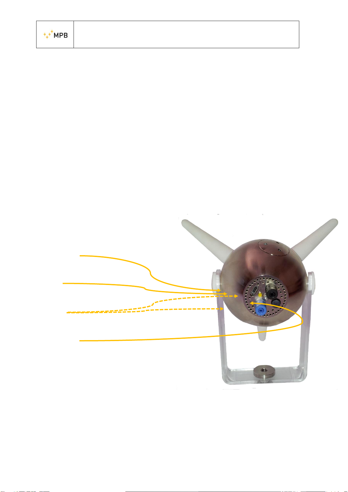
1.5 SEP Overview
USB connector
Status LED
Fiber Optic
ON/OFF
button
Figure 2

USER MANUAL
S E M S
- 8 -
1.6 Technical specifications
Frequency Range
Band1
Band2
Resolution
100 kHz to 9.999 MHz
10 MHz to 3.6 GHz
1 kHz
Reference Frequency
Aging year
Temperature drift (0° C to + 30° C)
1 x 10 - 5
5 x 10 - 6
Frequency Span
Range
Step number
100 kHz to full span
MIN 50; MAX 12000 (Each Axis)
Resolution Bandwidth
Range (-3 dB bandwidth)
Tolerance
3 kHz to 1 MHz 1/3 sequence
5%
Spectral Purity
SSB Phase Noise
@ 3 kHz (carries)
@ 30 kHz (carries)
@ 300 kHz (carries)
@ 1 GHz
< -85 dBc / Hz
<-90 dBc / Hz
<-102 dBc /Hz
Measurement Range
Max Level
Min Level @500 kHz
Min Level @10 to 100 MHz
Min Level @0.1 to 2 GHz
Min Level @2 to 3 GHz
Min Level @3 to 3.6 GHz
Damage Level
Dynamic Range @200 MHz
Linearity Error @200 MHz
200 v/m @ 10 MHz…3.6 GHz
1 v/m @ 3 kHz RBW
HW Detector Average
0.1 v/m @ 3 kHz RBW
HW Detector Average
0.02 v/m @ 3 kHz RBW
HW Detector Average
0.09 v/m @ 3 kHz RBW
HW Detector Average
0.1 v/m @ 3 kHz RBW
HW Detector Average
350 v/m @ 10 MHz…3.6 GHz
750 v/m < 2 MHz
>80 dB; 85 dB (Typ) @ 3 kHz RBW
HW Detector Average
<±0.5 dB @ 0.1…30 v/m (±0.25 dB Typ)
<±1 dB @ 0.03…100 v/m

USER MANUAL
S E M S
- 9 -
Flatness
@ 0.5 to 10 MHz
@ 10 to 2000 MHz
@ 2 to 3 GHz
@ 3 to 3.6 GHz
< ±1 dB @ 50 v/m
< ±1 dB @ 6 v/m
< ±1,2 dB @ 6 v/m
< ±1,5 dB @ 6 v/m
Isotropy
500 MHz
1000 MHz
2000 MHz
2500 MHz
@6 v/m; 3 kHz RBW; HW detector Average
<±0.5 dB ; < ±0.3 dB (Typ)
< ±0.6 dB (Typ)
< ±0.8 dB (Typ)
< ±1.3 dB (Typ)
Resolution Level
Max
Min
0.001 v/m
0.1 v/m
Spurious Response
Input related
Residual @HW detector Average
< -60 dBc (Typ)
0.1 v/m @ 30 MHz…1.5 GHz
0.2 v/m @ 10 MHz…3 GHz
Selectable Standards
Pre-defined
Correction Factor
Stored in EEPROM
Detectors HW
Peak, AVG and RMS
Antenna
Three-Axial X,Y and Z (identified by a led)
Positioned with an axis in vertical or all the axes
inclined at 54.7 degrees
I/O interface
Optical Link (connector-less type)
USB
Bluetooth
WiFi
Plastic Fiber Cable (max length 20mt.)
Micro –USB Connector
Fiber/Bluetooth Adapter
(distance max 20m in open air)
WiFi Radio link adpter
(distance max 300m in open air)
Operating Temperature
0° C to 50° C
Power Supply
Rechargeable/Replaceable Batteries
Operation Time
Battery Charger
Li-Ion 3.7 V
4h
4 slots battery 110…240 V
Dimensions
140 x 140 x 140 mm
Weight
370 g
Recommended Calibration Interval
24 months
Technical specifications may change without notice

USER MANUAL
S E M S
- 10 -
1.7 Software Specifications
Scale
Linear or semi-logarithmic
Data Acquisition
X,Y,Z selectable
Measurements
Marker
Limit (Horizontal Marker)
Isotropic
Max Hold
RMS
Average
Channel Power
Multi-Channel Power
Dragged marker with value V/m; W/; mW/; mV/m
Select the peaks over the selectable limit. Orderable in
frequency/amplitude
Root Mean Square value.
Selects the max value of the isotropic track
With selectable time (from 1 minute to 1 hour)
With selectable time (from 1 minute to 1 hour)
Selectable and dragged from 1 MHz to 20 MHz
Multiple simultaneous channel power with value acquisition
Report
Easy screenshots of measurements with the possibility to take
notes
Setup
Programmable, customizable. Saved setup can be stored
PC Requirements
OS
RAM
Resolution
Windows 7 –8 –8.1 –10
Minimum 2 GB
Minimum 800 x 600

USER MANUAL
S E M S
- 11 -
2. Operating principle
2.1. SEP
The block diagram below in Figure 3Figure 2 represents the functioning of the SEP
Figure 3 SEP logic scheme
The signal, received from the three dipoles (X, Y and Z), is selected by a switch
that directs it at the input of the receiver; the first stage of the superheterodyne receiver
converts the signal to the frequency of the first IF, where it is filtered and amplified,
before being re-converted to the frequency of the second IF, which makes it
downloadable from the analog to digital converter. The digital signal, as a result of
numerous and complex processing, is made available to the optical interface, that
transfers all the necessary data to the PC. Through the PC software MPB SEP, users
will be able to view real-time data while making measurements of revealed intensity
point by point, read the values integration over a frequency band and save the work
session as an image or data files, for a future check.
USER MANUAL
S E M S
- 12 -
3. SEP Use and operations
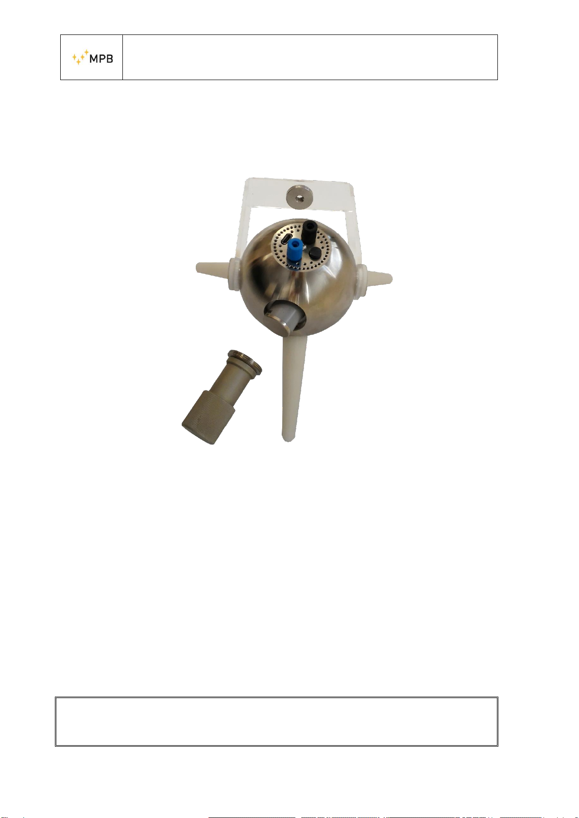
3.1. Power supply
Figure 4 Cap Remover
The SEP does not need external supply. It in fact uses two 3.7V lithium batteries, 49.3
mm long and 18.4 mm of diameter. This model (NCR18500) is manufactured by
Panasonic. The batteries compartments are located on the side of the device, that can
be opened by the cap remover supplied with the kit, as shown in Errore. L'origine
riferimento non è stata trovata..
The Cap remover is equipped with a magnet to help the user with the screwing
operation. The batteries have to be plugged with the positive side first. For recharging,
the user can
remove all the batteries and use the external 220V charger or plug the SEP micro-USB
connector to a simple charger min 1 Ampere and leave the batteries inside the device.
When screwing, please make sure the cap reaches the sphere surface without
tightening too much.

USER MANUAL
S E M S
- 13 -
3.2. Placement
Before any operation, plug the plexiglass support with a
tripod through the appropriate ¼“ threaded hole. In order
to have a better isotropy response from the SEP, please
perform the placement as in Figure 3.2. Please remember
to stay away from metal objects that may cause
electromagnetic reflections that may affect the
measurement.
3.3. Fiber Optic Plug
Insert the optical fiber in its room on the back of the SEP,
as in Figure 5 SEP on a tripodbeing careful to match the
optical fiber recognizable by the blue color with the color
of the corresponding connector. On the side of the PC,
the USB –RS232 converter must be installed with the
optical link, supplied with the kit.
In this case there is only one way to connect the optical
fiber
to the connector. For the installation of the converter
driver
3.4. Switch On/Off
To turn on the device, press the power button ON/OFF, shown in Figure 2. To turn it
off press the same button for around 4 seconds. Please remember that the SEP is not a
standalone device, so it has to be plugged to a PC for programming and for real-time
data visualization. To learn the software usage, please skip to Chapter 4.
Figure 5 SEP on a tripod

USER MANUAL
S E M S
- 14 -
4. Use and functioning of the software MPB SEP
Please note that this manual was written according to software version V 3.3
4.1. Prerequisites
The MPB SEP was developed for Windows platforms, with at least 2 GB of RAM and
preferably a dedicated video memory. The compatible operating systems are the
following:
Windows 7
Windows 8
Windows 8.1
Windows 10
It is also necessary the .NET Framework 4.0 (or next), that is free of charge through
the Windows Update system. In case the computer in use has no internet connection,
it is possible to use the installer provided in the USB key supplied with the kit, that
will add thenecessary inputs to execute the software.Even the USB –RS232 converter,
used to connect, through the fiber optic, the SEP to the PC, can be installed through the
automatic functionality of the Windows driver research or, in case of no internet
connection, using the manual installation mode of the driver, also provided in the USB
key supplied. If the computer meets these requirements and has installed the drivers of
the converter, you can proceed with the SEP software installation.
4.2. .NET Framework 4.0 installation
In order to verify which version of the .NET Framework is installed on the PC in use,
it is sufficient to open the control panel and check the programs installed. In the
Windows 7 version, if not automatically updated through Window Update, the most
recent framework versions could not be installed. This is why in the USB key supplied
is included the 4.0 version, that can be also installed offline. As for from Windows 8
on, this component is already part of the operating system.
USER MANUAL
S E M S
- 15 -
4.3. FTDI driver installation
In case of no internet connection, so in case an automatic research of the update driver
is not possible, the driver supplied with the USB key can be used. Please then plug the
USB –RS232 converter with the optical link to the PC (in this phase it is not necessary
to connect the fiber optic) and, in case the automatic installation will not work, choose
the manual installation mode by selecting the driver supplied with the USB pen driver.
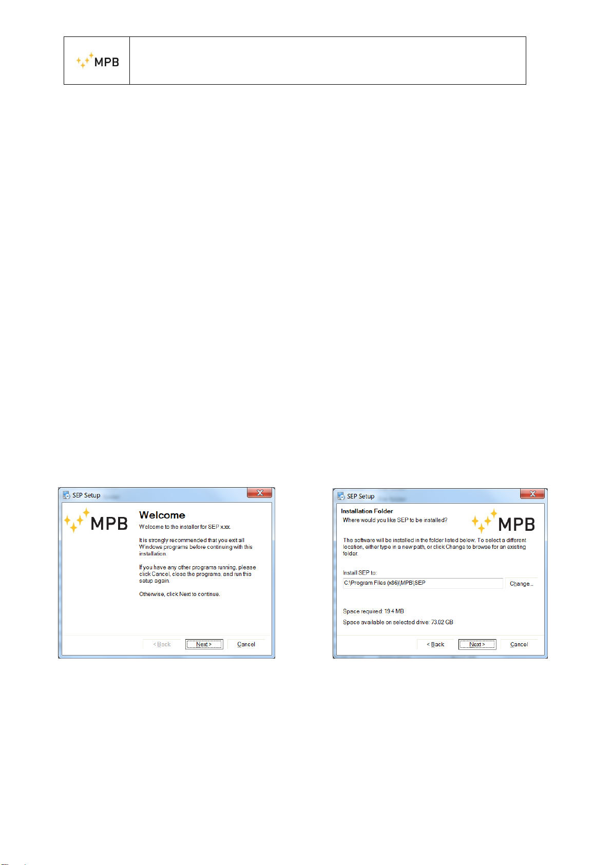
4.4. MPB SEP installation
Keeping the installer provided in the USB key, or downloading the software from our
website (gruppompb.uk.com), it will be possible to choose in which folder to install
the applicative (Figure 6(b)), edit the position of the links in the system menu, (Figure
6(c)). In the report (Figure 6(d)) are shown all the settings before proceeding with the
installation, at the end of whom the final confirmation screen of the operation will
appear (Figure 6(e)). Keeping the default settings, it will be possible to find the
application installed on the smart menu, in the “MPB S.r.l.” folder.
(a) Welcome (b) Patch

USER MANUAL
S E M S
- 16 -
(c) Link (d) Report
(e) End
Figure 6 Installer MPB SEP
USER MANUAL
S E M S
- 17 -
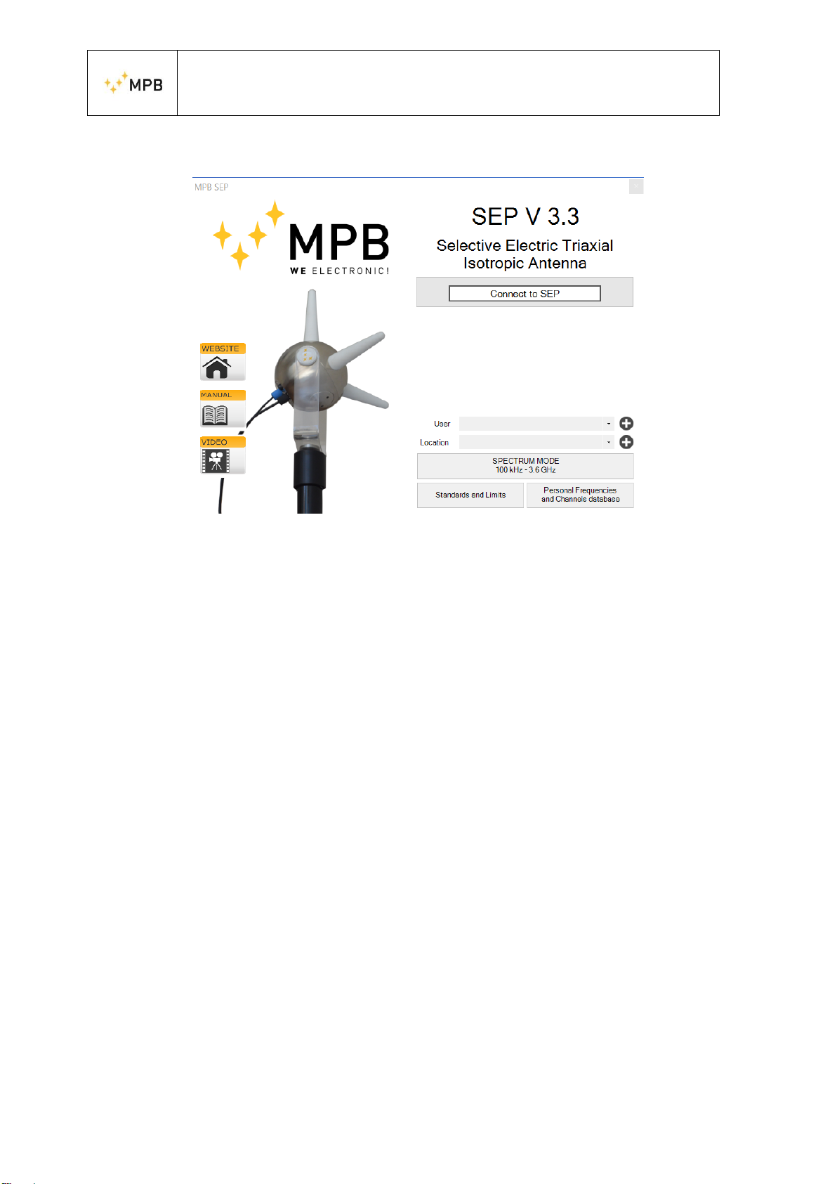
4.5. Software Home page
Figure 7 Home Page
[We recommend a screen resolution of 1920 x 1080 –with 100% screen configuration]
By pressing the “Connect” button, the software will attempt a connection with the
device, automatically finding the correct COM port. In case of eventual error message,
the software will warn the user asking to check the power status of the SEPor the driver
installation.
Once the connection is established, a green outline will confirm that the instrument is
connected and ready to make measurements. The MPB SEP will show under the
“Connect” button, the device information, such as the COM port used, the FW version
installed in the device, the serial number, the calibration date, the working mode and
the battery level.
Now, with the SEP connected, the “Spectrum Mode” will be enabled. Please note that
although the frequency range of the instrument is 100 kHz–3.6 GHz, two working
bands are allowed: “Band1” [100 kHz-9.999MHz] and “Band2”
[10MHz-3.6GHz]. By default, the instrument’s working mode is set on “Band2”. This
means that working in between “Band1” and “Band2” (e.g. a start frequency set at 9
MHz and stop frequency set at 20 MHz) is not allowed. It is recommended to insert
username and location in order to recall the data both on the graph and generated files.
On the left part of the panel, also three shortcuts are present:
Website: direct link to the MPB website
Manual: offline link to the SEP manual, added during the installation
Video: direct link to the MPB Youtube page
From the main screen, a measuring mode and two user commodity forms are available.

USER MANUAL
S E M S
- 18 -
4.5.1.Standards and Limits
Through this form, that can be opened even when the SEP is not connected, the user
can create standard files that the software will use to set limits and make measurements
according to those limits. The default standards in the software are four:
ICNIRP 2010 Occupational
ICNIRP 2010 General Public
Italy CM 2003 –Attention Value
Italy CM 2003 –Exposure Limits
Even the Standard files are exportable and importable from the pc, in order to favor the
expandability and collaboration. All standards can be also renamed, edited, deleted,
replaced or created from scratch.
Figure 8
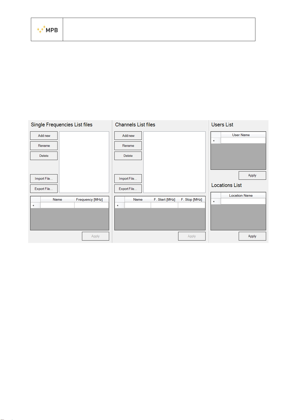
4.5.2.Personal Frequencies and Channels
This form allows creating files with frequencies, channels, users and locations that can
then be used when performing measurements for a quick recall, to fasten the
procedures. This form allows making “Single Frequencies List Files” to recall a set of
interest frequencies, and “Channels List Files” in case channels are required. The
procedure is the following: by pressing “Add new”, inserting the preferred name, press
“OK” and the file is created. To edit the created file please select the name in the list
USER MANUAL
S E M S
- 19 -
and the data grid viewis then enabled for editing, so to write the interested frequencies.
By pressing “Apply”, a confirmation message appears. In case invalid channels are set,
the software will warn the user by highlighting the sets in red. From this section on,
the files will be saved on the pc through the “Apply” button. Each section has its own
“Apply” button.
Please note that the “Single Frequencies List Files” will be shown in the “Limit”
section while “Channels List Files” will be shown in the “Multi-Channel Power”
section, see related sections (4.14.2 and 4.14.3) for more information.
Figure 9 Persona Database
4.6. Spectrum Mode
Once the SEP is connected, by selecting the “Spectrum Mode”, the scan will begin: on
top left, you will find first the MPB logo, then batterystatus, the voltage and fans status.

USER MANUAL
S E M S
- 20 -
Figure 10 MPB SEP Spectrum Mode
4.6.1.Graphics
To the right of the battery indicator, the
“Graphics” button is shown. By clicking
“Graphics”, a panel is shown (as in Figure 11
Graphics Panel) giving the user the possibility to
edit the view. From the top, the “Custom
Description” group is available: it firstly shows or
hide (by flagging or unflagging the “Show” –
related button) a default description that can be
edited by the user by pressing “Edit Description”,
according to his needs. Then the “Default” button
will restore on the top of the graph, the name and
location set before. As for the x-axis, the view can
be linear or logarithmic; as for the y-axis, it can
be both but is also available the y-range, that
represents the minimum and maximum view
point.
Figure 11 Graphics Panel
Table of contents
Other MPB Antenna manuals


Popular Antenna manuals by other brands


Panorama Antennas
Panorama Antennas LP MM Series installation instructions

Radio Shack
Radio Shack Six-Element Triple-Drive FM Antenna owner's manual

TERTEC Evolution
TERTEC Evolution 4G/LTE SAFE installation instructions

NETGEAR
NETGEAR ANT2407 - PROSAFE Indoor 7 dBi Omni-directional... installation guide

Poynting
Poynting OMNI-403 user guide

RCA
RCA ANT1450 - HDTV / TV user guide


