MTD series 780 User manual

Safe Operation Practices • Set-Up • Operation • Maintenance • Service • Troubleshooting • Warranty
OPER roR's L
Model Series 780 Lawn Tractor
MTD LLC, P.O. BOX 361131 CLEVELAND, OHiO 44136-0019
PrintedInUSA FormNo.769-08413
(December4,2012)

ToTheOwner 1
ThankYou
Thank you for purchasing a lawn tractor manufactured by MTD.
It was carefully engineered to provide excellent performance
when properly operated and maintained.
Please read this entire manual prior to operating the equipment.
It instructs you how to safely and easily set up, operate and
maintain your machine. Please be sure that you, and any other
persons who will operate the machine, carefully follow the
recommended safety practices at all times. Failure to do so could
result in personal injury or property damage.
All information in this manual is relative to the most recent
product information available at the time of printing. Review
this manual frequently to familiarize yourself with the machine,
its features and operation. Please be aware that this Operator's
Manual may cover a range of product specifications for various
models. Characteristics and features discussed and/or illustrated
in this manual may not be applicable to all models. MTD
reserves the right to change product specifications, designs and
equipment without notice and without incurring obligation.
If applicable, the power testing information used to establish
the power rating of the engine equipped on this machine can be
found at www.opei.org or the engine manufacturer's web site.
If you have any problems or questions concerning the machine,
phone your local authorized MTD service dealer or contact us
directly. MTD's Customer Support telephone numbers, website
address and mailing address can be found on this page. We want
to ensure your complete satisfaction at all times.
Throughout this manual, all references to fightand left side of the
machine are observed from the operating position
The engine manufacturer is responsible for all engine-related
issues with regards to performance, power-rating, specifications,
warranty and service. Please refer to the engine manufacturer's
Owner's/Operator's Manual, packed separately with your
machine, for more information.
Table of Contents
Safe Operation Practices ........................................ 3
Assembly &Set-Up .................................................. 9
Controls & Features ................................................ 12
Opera tion ................................................................ 15
Maintenance &Adjustment ................................. 18
Service .................................................................... 22
Troubleshooting .................................................... 26
Replacement Parts ................................................ 27
Attachments &Accessories .................................. 28
Emission Control Statement ................................. 30
Warranty ................................................................ 32
RecordProduct information
Before setting up and operating your new equipment, please
locate the model plate on the equipment and record the
information in the provided area to the right. You can locate the
model plate by looking beneath the seat. This information will
be necessary, should you seek technical support via our web site,
Customer Support Department, or with a local authorized service
dealer.
MODEL NUMBER
NNNNNNNNNND
SERIALNUMBER
DIqFllqFllqFllqNIqD
CustomerSupport
Please do NOT return the machine to the retailer or dealer without first contacting our Customer Support Department.
If you have difficulty assembling this product or have any questions regarding the controls, operation, or maintenance of
this machine, you can seek help from the experts. Choose from the options below:
0
0
0
I
Visit us on the web at www.mtdproducts.com
Call a Customer Support Representative at (800) 800-7310 or (330) 220-4683
See How-to Maintenance and Parts Installation Videos at www, mtdparts,com/KnowledgeCenter
Write us at MTD LLC •RO. Box 361131 •Cleveland, OH •44136-0019

ImportantSafeOperationPractices 2
WARNING! This symbol points out important safety instructions which, if not followed,
could endanger the personal safety and/or property of yourself and others. Read and follow
all instructions in this manual before attempting to operate this machine. Failure to comply
with these instructions may result in personal injury.
When you see this symbol. NEED ITS WARNING!
CALIFORNIA PROPOSITION 65
_ARNING! Engine Exhaust, some of its constituents, and certain vehicle components
contain or emit chemicals known to State of California to cause cancer and birth defects
or other reproductive harm.
_ARNING! Battery posts, terminals, and related accessories contain lead and lead
compounds, chemicals known to the State of California to cause cancer and reproductive
harm. Wash hands after handling
DANGER! This machine was built to be operated according to the safe operation practices in
this manual. As with any type of power equipment, carelessness or error on the part of the
operator can result in serious injury. This machine is capable of amputating hands and feet
and throwing objects. Failure to observe the following safety instructions could result in
serious injury or death.
GeneralOperation
1. Read, understand, and follow all instructions on the
machine and in the manual(s) before attempting to
assemble and operate. Keep this manual in a safe place for
future and regular reference and for ordering replacement
parts.
2. Be familiar with all controls and their proper operation.
Know how to stop the machine and disengage them
quickly.
3. Never allow children under 14 years of age to operate this
machine. Children 14 and over should read and understand
the instructions and safe operation practices in this manual
and on the machine and should be trained and supervised
by an adult.
4. Never allow adults to operate this machine without proper
instruction.
5. To help avoid blade contact or a thrown object injury,
keep bystanders, helpers, children and pets at least 75 feet
from the machine while it is in operation. Stop machine if
anyone enters the area.
6. Thoroughly inspect the area where the equipment is to be
used. Remove all stones, sticks, wire, bones, toys, and other
foreign objects which could be picked up and thrown by
the blade(s). Thrown objects can cause serious personal
injury.
7. Plan your mowing pattern to avoid discharge of material
toward roads, sidewalks, bystanders and the like. Also,
avoid discharging material against a wall or obstruction
which may cause discharged material to ricochet back
toward the operator.
8. Always wear safety glasses or safety goggles during
operation and while performing an adjustment or repair
to protect your eyes. Thrown objects which ricochet can
cause serious injury to the eyes.
9. Wear sturdy, rough-soled work shoes and close-fitting
slacks and shirts. Loose fitting clothes and jewelry can be
caught in movable parts. Never operate this machine in
bare feet or sandals.
10. Be aware of the mower and attachment discharge direction
and do not point it at anyone. Do not operate the mower
without the discharge cover or entire grass catcher in its
proper place.
11. Do not put hands or feet near rotating parts or under the
cutting deck. Contact with the blade(s) can amputate
hands and feet.

23.
24.
12. Amissingordamageddischargecovercancauseblade
contactorthrownobjectinjuries.
13. Stoptheblade(s)whencrossinggraveldrives,walks,or
roadsandwhilenotcuttinggrass.
14. Watchfortrafficwhenoperatingnearorcrossing
roadways.Thismachineisnotintendedforuseonany
publicroadway.
15. Donotoperatethemachinewhileundertheinfluenceof
alcoholordrugs.
16. Mowonlyindaylightorgoodartificiallight.
17. Nevercarrypassengers.
18. Disengageblade(s)beforeshiftingintoreverse.Backup
slowly.Alwayslookdownandbehindbeforeandwhile
backingtoavoidaback-overaccident.
19. Slowdownbeforeturning.Operatethemachinesmoothly.
Avoiderraticoperationandexcessivespeed.
20. Disengageblade(s),setparkingbrake,stopengineandwait
untiltheblade(s)cometoacompletestopbeforeremoving
grasscatcher,emptyinggrass,uncloggingchute,removing
anygrassordebris,ormakinganyadjustments.
21. Neverleavearunningmachineunattended.Alwaysturn
offblade(s),placetransmissioninneutral,setparking
brake,stopengineandremovekeybeforedismounting.
22. Useextracarewhenloadingorunloadingthemachineinto
atrailerortruck.Thismachineshouldnotbedrivenupor
downramp(s),becausethemachinecouldtipover,causing
seriouspersonalinjury.Themachinemustbepushed
manuallyonramp(s)toloadorunloadproperly.
Mufflerandenginebecomehotandcancauseaburn.Do
nottouch.
25.
26.
Checkoverheadclearancescarefullybeforedrivingunder
lowhangingtreebranches,wires,dooropeningsetc.,
wheretheoperatormaybestruckorpulledfromthe
machine,whichcouldresultinseriousinjury.
Disengageallattachmentclutches,depressthebrake
pedalcompletelyandshiftintoneutralbeforeattempting
tostartengine.
Yourmachineisdesignedtocutnormalresidentialgrassof
aheightnomorethan10".Donotattempttomowthrough
unusuallytall,drygrass(e.g.,pasture)orpilesofdryleaves.
Drygrassorleavesmaycontacttheengineexhaustand/
orbuilduponthemowerdeckpresentingapotentialfire
hazard.
27. Useonlyaccessoriesandattachmentsapprovedforthis
machinebythemachinemanufacturer.Read,understand
andfollowallinstructionsprovidedwiththeapproved
accessoryorattachment.
28. Dataindicatesthatoperators,age60yearsandabove,are
involvedinalargepercentageofridingmower-related
injuries.Theseoperatorsshouldevaluatetheirability
tooperatetheridingmowersafelyenoughtoprotect
themselvesandothersfromseriousinjury.
29. Ifsituationsoccurwhicharenotcoveredinthismanual,use
careandgoodjudgment.Contactyourcustomerservice
representativeforassistance.
SlopeOperation
Slopes are a major factor related to loss of control and tip-over
accidents which can result in severe injury or death. All slopes
require extra caution. If you cannot back up the slope or if you
feel uneasy on it, do not mow it.
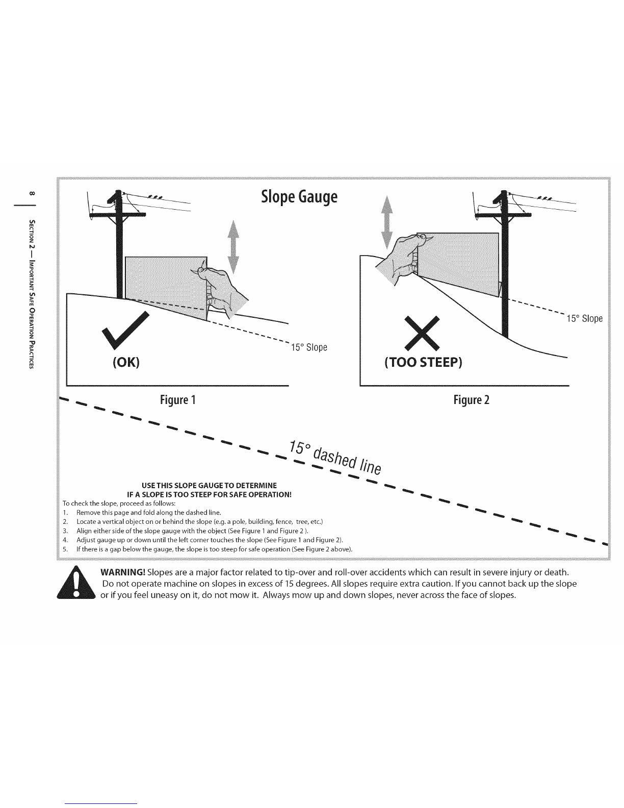
For your safety, use the slope gauge included as part of this
manual to measure slopes before operating this machine on
a sloped or hilly area. If the slope is greater than 15 degrees as
shown on the slope gauge, do not operate this machine on that
area or serious injury could result.
Do:
1. Mow up and down slopes, not across. Exercise extreme
caution when changing direction on slopes.
2. Watch for holes, ruts, bumps, rocks, or other hidden
objects. Uneven terrain could overturn the machine. Tall
grass can hide obstacles.
3. Use slow speed. Choose a low enough speed setting so
that you will not have to stop or shift while on the slope.
Tires may lose traction on slopes even though the brakes
are functioning properly. Always keep machine in gear
when going down slopes to take advantage of engine
braking action.
4. Follow the manufacturer's recommendations for wheel
weights or counterweights to improve stability.
5. Use extra care with grass catchers or other attachments.
These can change the stability of the machine.
6. Keep all movement on the slopes slow and gradual. Do
not make sudden changes in speed or direction. Rapid
engagement or braking could cause the front of the
machine to lift and rapidly flip over backwards which could
cause serious injury.
7. Avoid starting or stopping on a slope. If tires lose traction,
disengage the blade(s) and proceed slowly straight down
the slope.
DoNot:
1. Do not turn on slopes unless necessary;then, turn slowly
and gradually downhill, if possible.
2. Do not mow near drop-offs, ditches or embankments. The
mower could suddenly turn over if a wheel isover the edge
of a cliff, ditch, or if an edge caves in.
3. Do not try to stabilize the machine by putting your foot on
the ground.
4. Do not use agrass catcher on steep slopes.
5. Do not mow on wet grass.Reduced traction could cause
sliding.
6. Do not shift to neutral and coast downhill. Over-speeding
may cause the operator to lose control of the machine
resulting in serious injury or death.
7. Do not tow heavy pull behind attachments (e.g. loaded
dump cart, lawn roller, etc.) on slopes greater than 5
degrees. When going down hill, the extra weight tends
to push the tractor and may causeyou to loose control
(e.g.tractor may speed up, braking and steering ability are
reduced, attachment may jack-knife and cause tractor to
overturn).
4, I SECTION2 -- IMPORTANT SAFE OPERATION PRACTICES

Children
1. Tragic accidents ca n occur if the operator is not alert to the
presence of children. Children are often attracted to the
machine and the mowing activity. They do not understand
the dangers. Never assume that children will remain where
you last saw them.
a. Keep children out of the mowing area and in
watchful care of a responsible adult other than the
operator.
b. Be alert and turn machine off if a child enters the
area.
c. Before and while backing, look behind and down for
small children.
d. Never carry children, even with the blade(s) shut off.
They may fall offand be seriously injured or interfere
with safe machine operation.
e. Use extreme care when approaching blind corners,
doorways, shrubs, trees or other objects that may
blockyour vision of a child who may run into the
path of the machine.
f. To avoid back-over accidents, always disengage
the cutting blade(s) before shifting into Reverse.
If equipped, the "Reverse Caution Mode" should
not be used when chUdren or others are around.
2.
g. Keep children away from hot or running engines.
They can suffer burns from a hot muffler.
h. Remove key when machine is unattended to
prevent unauthorized operation.
Never allow children under 14 years of age to operate this
machine. Children 14 and over should read and understand
the instructions and safe operation practices in this manual
and on the machine and should be trained and supervised
by an adult.
Towing
1. Tow only with a machine that has a hitch designed for
towing. Do not attach towed equipment except at the
hitch point.
2. Follow the manufacturers recommendation for weight
limits for towed equipment and towing on slopes.
3. Never allow children or others in or on towed equipment.
4. On slopes, the weight of the towed equipment may cause
loss of traction and loss of control.
5. Always use extra caution when towing with a machine
capable of making tight turns (e.g. "zero-turn" ride-on
mower). Make wide turns to avoid jack-knifing.
6. Travel slowly and allow extra distance to stop.
7. Do not shift to neutral and coast downhill.
Service
SafeHandlingof Gasoline:
1. To avoid personal injury or property damage use extreme
care in handling gasoline. Gasoline is extremely
flammable and the vapors are explosive. Serious
personal injury can occur when gasoline is spilled on
yourself or your clothes which can ignite. Wash your skin
and change clothes immediately.
a. Use only an approved gasoline container.
b. Never fill containers inside a vehicle or on a truck
or trailer bed with a plastic liner. Always place
containers on the ground away from your vehicle
before filling.
c. When practical, remove gas-powered equipment
from the truck or trailer and refuel it on the ground.
If this is not possible, then refuel such equipment on
a trailer with a portable container, rather than from a
gasoline dispenser nozzle.
d. Keep the nozzle in contact with the rim of the fuel
tank or container opening at all times until fueling is
complete. Do not use a nozzle lock-open device.
e. Extinguish all cigarettes, cigars, pipes and other
sources of ignition.
f. Never fuel machine indoors.
g. Never remove gas cap or add fuel while the engine
is hot or running. Allow engine to cool at least two
minutes before refueling.
h. Never over fill fuel tank. Fill tank to no more than 1/2
inch below bottom of filler neck to allow space for
fuel expansion.
i. Replace gasoline cap and tighten securely.
j. If gasoline is spilled, wipe it off the engine and
equipment. Move machine to another area. Wait 5
minutes before starting the engine.
k. To reduce fire hazards, keep machine free of grass,
leaves, or other debris build-up. Clean up oil or fuel
spillage and remove any fuel soaked debris.
I. Never store the machine or fuel container inside
where there is an open flame, spark or pilot light
as on a water heater, space heater, furnace, clothes
dryer or other gas appliances.
m. Allow a machine to cool at least five minutes before
storing.
GeneralService
1. Never run an engine indoors or in a poorly ventilated area.
Engine exhaust contains carbon monoxide, an odorless,
and deadly gas.
2. Before cleaning, repairing, or inspecting, make certain the
blade(s) and all moving parts have stopped. Disconnect the
spark plug wire and ground against the engine to prevent
unintended starting.
SECTION 2 -- IMPORTANT SAFE OPERATION PRACTICES S

3. Periodically check to make sure the blades come to
complete stop within approximately (5) five seconds after
operating the blade disengagement control. If the blades
do not stop within the this time frame, your machine
should be serviced professionally by an authorized MTD
Service Dealer.
4. Check brake operation frequently as it is subjected to wear
during normal operation. Adjust and service as required.
5. Check the blade(s) and engine mounting bolts at frequent
intervals for proper tightness. Also, visually inspect blade(s)
for damage (e.g., excessive wear, bent, cracked). Replace
the blade(s) with the original equipment manufacturer's
(O.E.M.) blade(s) only, listed in this manual. "Use of parts
which do not meet the original equipment specifications
may lead to improper performance and compromise
safety!"
6. Mower blades are sharp. Wrap the blade or wear gloves,
and use extra caution when servicing them.
7. Keep all nuts, bolts, and screws tight to be sure the
equipment is in safe working condition.
8. Never tamper with the safety interlock system or other
safety devices. Check their proper operation regularly.
9. After striking a foreign object, stop the engine, disconnect
the spark plug wire(s) and ground against the engine.
Thoroughly inspect the machine for any damage. Repair
the damage before starting and operating.
10. Never attempt to make adjustments or repairs to the
machine while the engine is running.
11. Grass catcher components and the discharge cover are
subject to wear and damage which could expose moving
parts or allow objects to be thrown. For safety protection,
frequently check components and replace immediately
with original equipment manufacturer's (O.E.M.) parts only,
listed in this manual. "Use of parts which do not meet the
original equipment specifications may lead to improper
performance and compromise safety!"
12. Do not change the engine governor settings or over-speed
the engine. The governor controls the maximum safe
operating speed of the engine.
13. Maintain or replace safety and instruction labels, as
necessary.
14. Observe proper disposal laws and regulations for gas, oil,
etc. to protect the environment.
15. According to the Consumer Products Safety Commission
(CPSC) and the U.S. Environmental Protection Agency (EPA),
this product has an Average Useful Life of seven (7) years,
or 270 hours of operation. At the end of the Average Useful
Life have the machine inspected annually by an authorized
service dealer to ensure that all mechanical and safety
systems are working properly and not worn excessively.
Failure to do so can result in accidents, injuries or death.
Donotmodifyengine
To avoid serious injury or death, do not modify engine in any
way. Tampering with the governor setting can lead to a runaway
engine and cause it to operate at unsafe speeds. Never tamper
with factory setting of engine governor.
NoticeRegardingEmissions
Engines which are certified to comply with California and federal
EPA emission regulations for SORE (Small Off Road Equipment)
are certified to operate on regular unleaded gasoline, and
may include the following emission control systems: Engine
Modification (EM), Oxidizing Catalyst (OC), Secondary Air
Injection (SAI) and Three Way Catalyst (TWC) if so equipped.
When required, models are equipped with low permeation fuel
lines and fuel tanks for evaporative emission control. California
models may also include a carbon canister. Please contact
Customer Support for information regarding the evaporative
emission control configuration for your model.
SparkArrestor
WARNING!This machine is equipped with an
internal combustion engine and should not be used
on or near any unimproved forest-covered,
brushcovered or grass-covered land unless the
engine's exhaust system is equipped with a spark
arrestor meeting applicable local or state laws (if
any).
Ifa spark arrestor is used, it should be maintained in effective
working order by the operator. In the State of California the
above is required by law (Section 4442 of the California Public
Resources Code). Other states may have similar laws. Federal laws
apply on federal lands.
A spark arrestor for the muffler is available through your
nearest engine authorized service dealer or contact the service
department, P.O.Box 361131 Cleveland, Ohio 44136-0019.
WARNING! Your Responsibility--Restrict the use of this power machine to persons who read, understand and
follow the warnings and instructions in this manual and on the machine.
SAVETHESEINSTRUCTIONS!
6ISECTION 2 -- IMPORTANT SAFE OPERATION PRACTICES

SafetySymbols
This page depicts and describes safety symbols that may appear on this product. Read, understand, and follow all instructions on the
machine before attempting to assemble and operate.
O
J
Lq
M
N
A
READ THE OPERATOR'S MANUAL(S)
Read, understand, and follow all instructions in the manual(s) before attempting to
assemble and operate
DANGER-- ROTATING BLADES
Never carry passengers. Never carry children, even with the blades off.
DANGER-- ROTATING BLADES
Always look down and behind before and while backing to avoid a back-over accident.
WARNING-- ROTATING BLADES
Do not put hands or feet near rotating parts or under the cutting deck. Contact with the
blade(s) can amputate hands and feet.
WARNING--THROWN OBJECTS
This machine may pick up and throw and objects which can cause serious personal injury.
WARNING--THROWN OBJECTS
This machine may pick up and throw and objects which can cause serious personal injury.
BYSTANDERS
Keep bystanders, helpers, children and pets at least 75 feet from the machine while it is in
operation.
WARNING-- SLOPE OPERATION
Do not operate this machine on a slope greater than 15 degrees.
WARNING-- HOT SURFACE
Engine parts, especially the muffler, become extremely hot during operation. Allow engine
and muffler to cool before touching.
DANGER -- ROTATING BLADES
To reduce the risk of injury, keep hands and feet away. Do not operate unless discharge cover
or grass catcher is in its proper place. If damaged, replace immediately.
WARNING-- TOWING
Avoid jack-knifing when towing, go slow and make wide turns.
SECTION 2 -- IMPORTANT SAFE OPERATION PRACTICES 7

co
R
=4
z
I
z
-4
O
z
=o
-4 (OK) 15° Slope X
(TOO STEEP)
15° Slope
_Figure1
USE THiS SLOPE GAUGE TO DETERMINE
iF A SLOPE iS TOO STEEP FOR SAFE OPERATION[
To check the slope, proceed as follows:
1. Remove this page and fold along the dashed line.
2. Locate a vertical object on or behind the slope (e.g. a pole, building, fence, tree, etc.)
3. Align either side of the slope gauge with the object (See Figure 1 and Figure 2 ).
4. Adjust gauge up or clown until the left corner touches the slope (See Figure 1 and Figure 2).
5. If there is a gap below the gauge, the slope is too steep for safe operation (See Figure 2 above).
15°das2ed line
Figure2
WARN[NGI Slopes are a major factor related to tip-over and roll-over accidents which can result in severe injury or death.
Do not operate machine on slopes in excess of 15 degrees. All slopes require extra caution. If you cannot back up the slope
or if you feel uneasy on it, do not mow it. Always mow up and down slopes, never across the face of slopes.

Assembly&Set-Up 3
TractorSet-Up
NOTE:This Operators Manual covers a range of product
specifications for various models. Characteristics and features
discussed and/or illustrated in this manual may not be applicable
to all models. MTD reserves the right to change product
specifications, designs and equipment without notice and
without incurring obligation.
Connectingthe Battery Cables
CALIFORNIA PROPOSITION 65 WARNING:
Battery posts, terminals, and related accessories
contain lead and lead compounds, chemicals known
to the State of California to cause cancer and
reproductive harm. Wash hands after handling.
CAUTION: When attaching battery cables, always
connect the POSITIVE (Red) wire to its terminal first,
followed by the NEGATIVE (Black) wire.
For shipping reasons, both battery cables on your equipment
may have been left disconnected from the terminals at the
factory. To connect the battery cables, proceed as follows:
NOTE:The positive battery terminal is marked Pos. (+). The
negative battery terminal is marked Neg. (-).
1. Remove the plastic cover, if present, from the positive
battery terminal and attach the red cable to the positive
battery terminal (+) with the bolt and hex nut. See Fig. 1-1.
2. Removethe plasticcover, if present, fromthe negative battery
terminal and attach the black cable to the negative battery
terminal (-) with the bolt and hex nut. See Fig. 1-1.
3. Positionthe red rubberbootoverthe positivebatteryterminalto
help protect it from corrosion.
NOTE: If the battery is put into service after the date shown
on top/side of battery, charge the battery as instructed in the
Maintenance section your Operator's Manual prior to operating
the tractor.
Shipping BraceRemoval
WARNING! Make sure the riding mower's engine is
off, remove the ignition key, and set the parking
brake before removing the shipping brace. Refer to
the Controls and Features section for instructions on
how to set the parking brake.
Locate the shipping brace, if present, and accompanying
warning tag found on the right side of the mower, between
the discharge chute and the cutting deck. See Fig. 3-2.
Place the deck lift lever in the highest cutting position.
Refer to Setting the Cutting Height in the Operation
section of this manual.
While pushing the discharge chute towards the machine
with your left hand, remove the shipping brace with your
right hand by grasping it between your thumb and index
finger and rotating it clockwise.
WARNING!The shipping brace, used for
packaging purposes only, must be removed and
discarded before operating your riding mower.
WARNING! The mowing deck is capable of
throwing objects. Failure to operate the riding
mower without the discharge cover in the proper
operating position could result in serious personal
injury and/or property damage.
Figure 3=2

AttachingTheSteeringWheel
If the steering wheel for your tractor did not come attached, the
hardware for attaching it has been packed within the steering
wheel, beneath the steering wheel cap. Carefully pry off the
steering wheel cap and remove the hardware.
1. With the wheels of the tractor pointing straight forward,
place the steering wheel over the steering shaft.
2. Place the washer (with the cupped side down) over the
steering wheel and secure with the hex bolt. See Fig. 3-3.
3. Place the steering wheel cap over the center of the steering
wheel and push downward until it "clicks" into place.
5_
Figure 3-4
To adjust the position of the seat, remove the adjustment
bolt on the bottom of the seat. Slide the seat forward or
backward as desired. Reinstall the adjustment bolt. See
Figure 3-5.
Figure 3-3
Attaching TheSeat
If the seat for your tractor was not attached at the factory, refer
to the following steps.
NOTE: For shipping reasons, seats are either fastened to the
tractor seat's pivot bracket with a plastic tie, or mounted
backward to the pivot bracket. In either case, free the seat from
its shipping position and remove the adjustment knob from the
bottom of seat before proceeding with the instructions below.
1. Asalreadyinstructed,removetheseatadjustmentboltinstalled
by the factory in the bottom of the seat. See "a" in Figure
3-4.
2. Aligntheseatovertheseat pivotbracketasshownin Figure3-4
and fit the seat onto the pivot bracket inserting the two
tabs on the seat bottom into the slots on the pivot bracket.
3. Slidetheseatrearwardintheseat pivotbracket(c),lining upthe
center rear slot in the pivot bracket with the remaining hole
in the seat's base. See Figure 3-5.
Note: Be certain the two seat tabs engauge the pivot
bracket as shown in the bottom inset of Figure 3-5.
4. Select desired position for the seat, and secure with the
adjustment bolt removed earlier (d in Figure 3-5).
Figure 3-5
TirePressure
_ARNING! Maximum tire pressure under any
circumstances is 30 psi. Equal tire pressure should be
maintained at all times. Never exceed the maximum
inflation pressure shown on the sidewall of the tire.
The recommended operating tire pressure is:
Approximately 10 psi for the rear tires
Approximately 14 psi for the front tires
IMPORTANT: Refer to the tire sidewall for exact tire
manufacturer's recommended or maximum psi.Do not
overinflate. Uneven tire pressure could causethe cutting deck to
mow unevenly.
SECTION 3-- ASSEMBLY& SET-UP

Gasand OilFill-up
The gasoline tank is located under the hood. Do not overfill.
i_k WARNING! Use extreme care when handling
gasoline. Gasoline is extremely flammable and the
vapors are explosive. Never fuel machine indoors or
while the engine is hot or running. Extinguish
cigarettes, cigars, pipes, and other sources of ignition.
IMPORTANT: Do not overfill the tank. Fill tank to no more
than 1/2 inch below bottom of filler neck to allow space for fuel
expansion. See Fig. 3-5.
IMPORTANT: Your tractor is shipped with motor oil in the
engine. However, you MUST check the oil level before
operating. Be careful not to overfill.
Service and check the engine oil as instructed in the separate
Engine Operator/Owner Manual packed with your tractor. Read
the instructions carefully.
Setting the DeckGaugeWheels(IfEquipped)
Move the tractor on a firm and level surface, preferably
pavement, and proceed as follows
I. Select the height position of the cutting deck by placing
the deck lift lever in the normally desired mowing height
setting (any of the six different cutting height notches on the
righ t fender).
2. Check the gauge wheels for contact or excessive clearance
with the surface below. The deck gauge wheels should
have between 1/4-inch and 1/2-inch clearance above the
ground as follows:
If the gauge wheels have excessive clearance or contact with the
surface, adjust as follows:
a. Raise the deck lift handle to its highest setting.
b. Remove the gauge wheels by removing the lock
nuts and shoulder screws which secure them to the
deck. See Fig. 3-6.
Figure 3-6
Figure 3-7
c. Place the deck lift lever in the desired mowing height
setting.
d. Reinsert the shoulder screw (with each gauge wheel)
into the index hole that leaves approximately
1/2-inch between the bottom of the wheel and the
pavement.
Refer to Leveling the Deck in the Maintenance section of this
manual for more detailed instructions regarding various deck
adjustments.
SECTION3 -- ASSEMBLY&SET-UP 11

Controls& Features 4
Throttle/Choke Lever \ignition Switch
Brake Peclal
Parking Brake Lever
Drive Pedal
Shift Lever
Deck Lift Lever
Cup Holder PTO (Blade Engage) Lever
NOTE: Steering wheel not shown for clarity J
Figure 4=1
Lawn Tractor controls and features are illustrated in Figure 4-1 and described on the following pages.
WARNING! Read and follow all safety rules and instructions in this manual, including the entire Operation section,
before attempting to operate this machine. Failure to comply with all safety rules and instructions may result in personal
injury.
12

Throttle/ChokeControl
The throttle control lever is located on the left side
of the tractor's dash panel. This lever controls the
speed of the engine, as well as the choke when it
is pushed all the way forward. When set in a given
position, the throttle will maintain a uniform engine
speed.
IMPORTANT: When operating the tractor with the
cutting deck engaged, be certain that the throttle
lever is always in the FAST (rabbit) position.
Moving the throttle lever all the way forward
activates the engine's choke control. Activating
the choke control closes the choke plate on the
carburetor and aids in starting the engine.
Refer to Starting The Engine in the Operation
section of this manual for detailed starting
instructions.
Ignition Switch
The ignition switch is activated to start the engine.
Insert key into the ignition switch and turn clockwise to the
START position. Release the key into the ON position once engine
has fired. See Figure 4-2.
WARNING! Never leave a running machine
unattended. Always disengage PTO, move shift lever
into neutral position, set parking brake, stop engine
and remove key to prevent unintended starting.
IMPORTANT: Prior to operating the tractor, refer to both Safety
Interlock Switches and Starting The Engine in the Operation section
of this manual for detailed instructions regarding the Ignition Switch.
off
On/Lights
Figure 4=2
ShiftLever
The shift lever is located on the left side of the fender and has
three positions, FORWARD, NEUTRAL and REVERSE.The tractor
must not be in motion when the moving shift lever. See Figure
4-3.
IMPORTANT: Never force the shift lever. Doing so may result in
serious damage to the tractor's transmission.
f
4_
REVERSE _
Figure 4=3
BrakePedal
The brake pedal is located on the left side of the lawn tractor,
along the running board. Depress the pedal all the way down to
engage the disc brake and bring the tractor to a complete stop.
NOTE:The pedal must be depressed to start the engine. Refer to
Safety Interlock Switches in the Operation section of this manual.
ParkingBrake
To set the parking brake: Fully depress the
brake pedal. Move the parking brake lever into the
parking brake position. Release the brake pedal to
allow the parking brake to engage.
To release the parking brake: Depress the brake
pedal and the parking brake lever will move out of
the parking brake position on its own. The parking
brake will then be released. Release the brake
pedal.
NOTE:The parking brake must be set if the
operator leaves the seat with the engine running
or the engine will automatically shut off.
SECTION 4 -- CONTROLS &FEATURES 13

DrivePedal
The drive pedal is located on the right side of the
tractor, along the running board. Depress the
drive pedal forward and the tractor will move in
the direction that the shift lever is engaged in.
To cause the tractor to travel forward, while at
a complete stop, move the shift lever into the
Forward position. Gradually step on the drive
pedal and the tractor will begin to move forward.
To move in Reverse, follow the same procedure
only move the shift lever into the reverse position.
The ground speed is controlled with the drive
pedal. The further forward that the pedal is
4e
M
MW
pivoted, the faster the tractor will travel. The pedal will return
to its original position when it's not depressed. Refer to the
Operation section of this manual for detailed instructions
regarding the drive pedal.
IMPORTANT: Always set the parking brake when leaving the
tractor unattended.
DeckLift Lever
Found on your tractor's right fender, the deck lift
lever is used to change the height of the cutting
deck. To use, move the lever to the left, then place in
the notch best suited for your application.
PTO(BladeEngage)Lever
Found on the tractor's right fender, the PTO (blade
engage) lever is used to engage power to the cutting
deck. To operate, move the lever all the way forward.
Moving the lever all the way rearward into the PTO
OFF position disengages power to the cutting deck.
NOTE:The PTO (blade engage) lever must be in the
disengaged (PTO OFF) position when starting the
engine.
z
41_
m
o
w
m
z
o
m/I
SECTION 4-- CONTROLS & FEATURES

Operation
TO AVOID SERIOUS INJURY
OR DEATH
•GOUPANDDOWNSLOPES,NOTACROSS.
•AVOIDSUDDENTURNS.
•D0 NOTOPERATETHE UNITWHEREIT COULDSLIP
ORTIP.
• IF MACHINESTOPSGOINGUPHILL,STOPBLADE(S)
ANDBACKDOWNHILLSLOWLY.
•KEEPSAFETYDEVICES(GUARDS,SHIELDS,
ANDSWITCHES,ETC.) IN PLACEANDWORKING.
•REMOVEOBJECTSTHATCOULDBETHROWN
BYTHE BLADE(S).
•KNOWLOCATIONANDFUNCTIONOFALLCONTROLS.
•BESUREBLADE(S)ANDENGINEARESTOPPED
BEFOREPLACINGHANDSORFEETNEARBLADE(S).
•BEFORELEAVINGOPERATOR'SPOSITION,
DISENGAGEBLADE(S),ENGAGEPARKINGBRAKE,
SHUTOFFANDREMOVEKEY.
READ OPERATOR'S
MANUAL
SafetyinterlockSwitches
This tractor is equipped with a safety interlock system for the
protection of the operator. If the interlock system should ever
malfunction, do not operate the tractor. Contact an authorized
Troybilt service dealer.
The safety interlock system prevents the engine from
cranking or starting unless the parking brake is engaged,
and the PTO (Blade Engage) lever is in the disengaged (OFF)
position.
The engine will automatically shut off if the operator leaves
the seat before engaging the parking brake.
The engine will automatically shut off if the operator leaves
the tractor's seat with the PTO (Blade Engage) lever in the
engaged (ON) position, regardless of whether the parking
brake is engaged.
The engine will automatically shut off if the PTO (Blade
Engage) lever is moved into the engaged (ON) position with
the shift lever in Reverse.
WARNING! Do not operate the tractor if the
interlock system is malfunctioning. This system was
designed for your safety and protection.
Engagingthe ParkingBrake
Toengagethe parkingbrake:
1. Fully depress the brake pedal and hold it down with your
foot.
2. Move the parking brake lever down into the parking brake
position.
3. Release the brake pedal to allow the parking brake to
engage.
Toreleasethe parking brake:
I. Depress the brake pedal and the parking brake lever will
automatically move out of the parking brake position.
Setting the (utting Height
1. Select the height position of the cutting deck by placing
the deck lift lever in any of the different cutting height
notches on the right side of the fender.
WARNING! Keep hands and feet away from the
discharge opening of the cutting deck.
Refer to Leveling the Deck in the Maintenance & Adjustments
section of this manual for more detailed instructions regarding
various deck adjustments.
Starting the Engine
WARNING! Do not operate the tractor if the
interlock system is malfunctioning. This system was
designed for your safety and protection.
NOTE: Refer to the Assembly & Set-Up section of this manual for
gasoline and oil fill-up instructions.
1. Insert the tractor key into the ignition switch.
2. Place the PTO (Blade Engage) lever in the disengaged (OFF)
position.
3. Engage the tractor's parking brake.
4. Activate the choke control.
5. Turn the ignition key clockwise to the START position. After
the engine starts, release the key. It will return to the ON
position.
IMPORTANT: Do NOT hold the key in the START position
for longer than ten seconds at a time. Doing so may cause
damage to your engine's electric starter.
6. After the engine starts, deactivate the choke control and
place the throttle control in the FAST position.
NOTE: Do NOT leave the choke control on while operating the
tractor. Doing so will result in a "rich" fuel mixture and cause the
engine to run poorly.

Stoppingthe Engine
1.
2.
3.
WARNING! If you strike a foreign object, stop the
engine, disconnect the spark plug wire(s) and
ground against the engine. Thoroughly inspect the
machine for any damage. Repair the damage before
restarting and operating.
If the blades are engaged, place the PTO (Blade Engage)
lever in the disengaged (OFF) position.
Turn the ignition key counterclockwise to the STOP
position.
Remove the key from the ignition switch to prevent
unintended starting.
Driving TheTractor
WARNING! Avoid sudden starts, excessive speed
and sudden stops.
WARNING! Do not leave the seat of the tractor
without first placing the PTO (Blade Engage) lever in
the disengaged (OFF) position, depressing the brake
pedal and engaging the parking brake. If leaving
the tractor unattended, also turn the ignition key off
and remove the key.
WARNING! Always look down and behind before
and while backing up to avoid a back-over accident.
1. Depress the brake pedal to release the parking brake and
let the pedal up.
2. Move the throttle lever into the FAST (rabbit) position.
3. Place the shift lever in either the FORWARD or REVERSE
position.
CAUTION: Do NOT use the shift lever to change
the direction of travel when the tractor is in motion.
Always use the brake pedal to bring the tractor to a
complete stop before shifting.
IMPORTANT: First-time operators should become
completely familiar with the tractor's operation and controls
before operating the tractor in higher speed positions.
4. Gradually begin to apply pressure to the drive pedal. The
further down the pedal is pushed, the faster the tractor will
travel in the desired direction based on the position of the
shift lever.
S. The lawn tractor is brought to a stop by releasing the drive
pedal and then depressing the brake pedal.
WARNING! Before leaving the operator's position
for any reason, disengage the blades, place the shift
lever in neutral, engage the parking brake, shut
engine off and remove the key.
IMPORTANT: When stopping the tractor for any reason while
on a grass surface, always:
1. Place the shift lever in neutral,
2. Engage the parking brake,
3. Shut engine off and remove the key.
Doing so will minimize the possibility of having your lawn
"browned" by hot exhaust from your tractor's running engine.
Driving OnSlopes
Refer to the SLOPE GAUGE in the Important Safe Operation
Practices section in the front of this manual to help determine
slopes where you may operate the tractor safely.
WARNING! Do not mow on inclines with a slope in
excess of 15 degrees (a rise of approximately2-1/2 feet
every 10feet). The tractor could overturn and cause
serious injury.
Mow up and down slopes, NEVER across.
Exercise extreme caution when changing direction on
slopes.
Watch for holes, ruts, bumps, rocks, or other hidden
objects. Uneven terrain could overturn the machine. Tall
grass can hide obstacles.
Avoid turns when driving on a slope. Ifa turn must be
made, turn down the slope. Turning up a slope greatly
increases the chance of a roll over.
Avoid stopping when driving up a slope. If it is necessary
to stop while driving up a slope, start up smoothly and
carefully to reduce the possibility of flipping the tractor
over backward.
Engagingthe Blades
Engaging the PTO (Blade Engage) transfers power to the cutting
deck. To engage the blades, proceed as follows:
1. Move the throttle control lever to the FAST (rabbit)
position.
2. Grasp the PTO (Blade Engage) lever and pivot it all the way
forward into the engaged (ON) position.
3. Keep the throttle lever in the FAST (rabbit) position for the
most efficient use of the cutting deck.
IMPORTANT: The PTO (Blade Engage) lever must be in the
disengaged (OFF) position when starting the engine, when
traveling in reverse, and if the operator leaves the seat. Refer to
Safety Interlock Switches in the Operation section of this manual.
'°1SECTION S-- OPERATION

Usingthe DeckLiftLever
To raise the cutting deck, move the deck lift lever to the left, then
place it in the notch best suited for your application. Refer to
Setting The Cutting Height earlier in this section.
Mowing
WARN[ NG! To help avoid blade contact or a
thrown object injury, keep bystanders, helpers,
children and pets at least 75 feet from the machine
while it is in operation. Stop machine if anyone
enters the area.
The following information will be helpful when using the cutting
deck with your tractor:
i_i WARNING! Plan your mowing pattern to avoid
discharge of materials toward roads, sidewalks,
bystanders and the like. Also, avoid discharging
material against a wall or obstruction which may
cause discharged material to ricochet back toward
the operator.
Do not mowat high ground speed, especially ifa mulch kit
or grass collector is installed.
For best results it is recommended that the first two laps be
cut with the discharge thrown towards the center. After the
first two laps, reverse the direction to throw the discharge
to the outside for the balance of cutting. This will give a
better appearance to the lawn.
Do not cut the grass too short. Short grass invites weed
growth and yellows quickly in dry weather.
Mowing should always be done with the engine at full
throttle.
Under heavier conditions it may be necessary to go back
over the cut area a second time to get a clean cut.
Do NOT attempt to mow heavy brush and weeds and
extremely tall grass. Your tractor is designed to mow lawns,
NOT clear brush.
Keep the blades sharp and replace the blades when worn.
Referto Cutting Blades in the Service section of this manual
for proper blade sharpening instructions.
Headlights
The Headlights are ON whenever the tractor's engine is
running.
The lamps turn OFF when the ignition key is moved to the
STOP position.
SECTION 5 -- OPERATION 17

Maintenance&Adjustments 6
Maintenance
WARNING: Before performing any maintenance or
repairs, disengage PTO, move shift lever into neutral
position, set parking brake, stop engine and remove
key to prevent unintended starting.
Refer to the Engine Operator/Owner Manual for engine
maintenance instructions.
Check engine oil level before each use as instructed in the Engine
Operator/Owner Manual packed with your unit. Follow the
instructions carefully.
ChangingEngineOil
For draining oil from the engine's crankcase, a plastic oil drain
sleeve is packed with this Operator's Manual. To drain the oil,
proceed as follows:
1. Run the engine for a few minutes to allow the oil in the
crankcase to warm up. Warm oil will flow more freely and
carry away more of the engine sediment which may have
settled at the bottom of the crankcase. Use care to avoid
burns from hot oil.
2. Open the tractor's hood and locate the oil drain port on the
right side of the engine and the oil fill cap on the topside of
the engine.
3. Unscrew the oil fill cap and remove the dipstick from the oil
fill tube.
4. Snap the small end of oil drain sleeve onto the space
provide around the oil drain plug. See Figure 6-1.
5. Remove drain plug and drain oil into a suitable container
with a capacity of no less than 64 oz.
F
Figure 6-1
6.
7. Reinstall the oil drain plug securely. Be careful not to
overtighten.
4. Refill the engine with new motor oil as instructed in the
Engine Owner's Manual packed with your unit.
IMPORTANT: Refer to the Engine Owner's Manual packed with
your unit for information regarding the quantity and proper
viscosity of motor oil.
Air Cleaner
Service the pre-cleaner and cartridge/air cleaner element as
instructed in the Engine Operator/Owner Manual packed with
your unit.
SparkPlug
The spark plug should be cleaned and the gap reset once a
season. Spark plug replacement is recommended at the start
of each mowing season. Refer to the Engine Operator/Owner
Manual for correct plug type and gap specifications.
Lubrication
_ ARNING: Before lubricating, repairing, or
inspecting, always disengage PTO, move shift lever
into neutral position, set parking brake, stop engine
and remove key to prevent unintended starting.
Engine
Lubricate the engine with motor oil as instructed in the Engine
Owner Manual packed with your unit.
Pivot Points& Linkage
Lubricate all the pivot points on the drive system, parking brake
and lift linkage at least once a season with light oil.
RearWheels
The rear wheels should be removed from the axles once a
season. Lubricate the axles and the rims well with an all-purpose
grease before re-installing them.
Cleaningthe EngineAndDeck
Any fuel or oil spilled on the machine should be wiped off
promptly. Do NOT allow debris to accumulate around the cooling
fins of the engine or on any other part of the machine.
IMPORTANT: The use of a pressure washer to clean your
tractor is NOT recommended. It may cause damage to electrical
components, spindles, pulleys, bearings or the engine.
18

DeckWashSystemTM
A hex bolt and washer can be found on your tractor's deck surface.
See Figure 6-2.
jf
/
/
J i\
Deck Wash Plug
Figure 6=2
This bolt and washer can be replaced with a water port to be
used as part of a separately-available deck wash system.
The Deck Wash System TM is used to rinse grass clippings from the
deck's underside and prevent the buildup of corrosive chemicals.
NOTE: Refer to the Attachments & Accessories section of this
manual for information regarding this and other separately-
available attachments and accessories for your tractor.
The battery is sealed and is maintenance-free. Acid levels cannot
be checked.
Always keep the battery cables and terminals clean and
free of corrosive build-up.
After cleaning the battery and terminals, apply a light coat
of petroleum jelly or grease to both terminals.
Always keep the rubber boot positioned over the positive
terminal to prevent shorting.
IMPORTANT: If removing the battery for any reason,
disconnect the NEGATIVE (Black) wire from it's terminal first,
followed by the POSITIVE (Red) wire. When re-installing the
battery, always connect the POSITIVE (Red) wire its terminal
first, followed by the NEGATIVE (Black) wire. Be certain that the
wires are connected to the correct terminals; reversing them
could change the polarity and result in damage to your engine's
alternating system.
Charging
IMPORTANT: When charging your tractor's battery, use only a
charger designed for 12V lead-acid batteries. Read your battery
charger's Owner's Manual prior to charging your tractor's battery.
Always follow its instructions and heed its warnings.
If your tractor has not been put into use for an extended period
of time, charge the battery as follows:
Set your battery charger to deliver a maximum of I0
amperes. If your battery charger is automatic, charge
the battery until the charger indicates that charging is
complete.
NOTE: If the charger is not automatic, charge for no fewer than
eight hours.
WARNING! Batteries give off an explosive gas
while charging. Charge battery in a well ventilated
area and keep away from an open flame or pilot
light as on a water heater, space heater, furnace,
clothes dryer or other gas appliances.
JumpStarting
WARNING!When removing or installing the
battery, follow these instructions to prevent the
screwdriver from shorting against the frame.
IMPORTANT: Never jump your tractor's dead battery with the
battery of a running vehicle.
1. Connect end of one jumper cable to the positive terminal
of the good battery, then the other end to the positive
terminal of the dead battery.
2. Connect the other jumper cable to the negative terminal
of the good battery, then to the frame of the unit with the
dead battery.
3. Start the tractor as instructed in the Operation section.
WARNING! Failure to use this procedure could
cause sparking, and the gas in either battery could
explode.
CleaningBattery
Clean the battery by removing it from the tractor and washing
with a baking soda and water solution. If necessary, scrape the
battery terminals with a wire brush to remove deposits. Coat
terminals and exposed wiring with grease or petroleum jelly to
prevent corrosion.
Battery Failures
Some common causes for battery failure are:
Incorrect initial activation
Overcharging
Freezing
Undercharging
Corroded connections
These failures are NOT covered by your tractor's warranty.
SECTION 6-- MAINTENANCE & ADJUSTMENTS 19

Adjustments
WARNING" Never attempt to make any
adjustments while the engine isrunning, except
where specified in the operator's manual.
Levelingthe Deck
NOTE: Check the tractor's tire pressure before performing any
deck leveling adjustments. Refer to Tires in the Service section of
this manual for information regarding tire pressure.
Front ToRear
The front of the cutting deck is supported by a stabilizer bar that
can be adjusted to level the deck from front to rear. The front of
the deck should be between 1/4-inch and 3/8-inch lower than the
rear of the deck. Adjust if necessary as follows:
1. With the tractor parked on a firm, level surface, place the
lever for lifting the platform on the second to the top notch
(second highest position) and rotate the blade as close to
the discharge channel that is parallel to the tractor.
2. Measure the distance from the front of the blade tip to
the ground and the rear of the blade tip to the ground.
The first measurement taken should be between 1/4"and
3/s" less than the second measurement. Determine the
approximate distance necessary for proper adjustment and
proceed, if necessary, to the next step.
3. Locate the flange lock nut on the front side of the stabilizer
bracket. See Figure 6-3.
Tighten the lock nut to raise the front of the deck;
Loosen the lock nut to lower the front of the deck.
JJ
Figure 6-3
Sideto Side
If the cutting deck appears to be mowing unevenly, a side to side
adjustment can be performed. Adjust if necessary as follows:
1. With the tractor parked on a firm, level surface, place the
deck lift lever in the second from the top notch (second
highest position) and rotate both blades so that they are
perpendicular with the tractor.
2. Measure the distance from the outside of the left blade
tip to the ground and the distance from the outside of the
right blade tip to the ground. Both measurements taken
should be equal. If they're not, proceed to the next step.
3. Loosen, but do NOT remove, the hex cap screw on the left
deck hanger bracket. See Figure 6-4.
f
J
Figure 6-4
4. Balance the deck by using a wrench to turn the adjustment
gear (found immediately behind the hex cap screw just
loosened) clockwise/up or counterclockwise/down.
The deck is properly balanced when both blade tip
measurements taken earlier are equal.
5. Retighten the hex cap screw on the left deck hanger
bracket when proper adjustment is achieved.
SeatAdjustment
Refer to the Set-Up and Assembly section of this manual for seat
adjustment instructions.
ParkingBrakeAdjustment
WARNING: Never attempt to adjust the brakes
while the engine is running. Always disengage PTO,
move shift lever into neutral position, stop engine
and remove key to prevent unintended starting.
If the tractor does not come to a complete stop when the brake
pedal is completely depressed, or if the tractor's rear wheels
can roll with the parking brake applied, the brake is in need of
adjustment. See an authorized MTD Service Dealer to have your
brakes properly adjusted.
SECTION 6-- MAINTENANCE & ADJUSTMENTS
Other manuals for series 780
1
Table of contents
Other MTD Lawn Mower manuals

MTD
MTD 142-760 User manual

MTD
MTD 117-620-300 User manual

MTD
MTD 123-460A000 User manual

MTD
MTD 214 KW User manual

MTD
MTD 182-097B000 User manual

MTD
MTD 2005 800 Series User manual

MTD
MTD Series V560 User manual

MTD
MTD White Outdoor 465 Series User manual

MTD
MTD Rover Rancher 1742 User manual

MTD
MTD 138-472A User manual