830-860 SERIES SELF-PROPELLED MOWERS
1
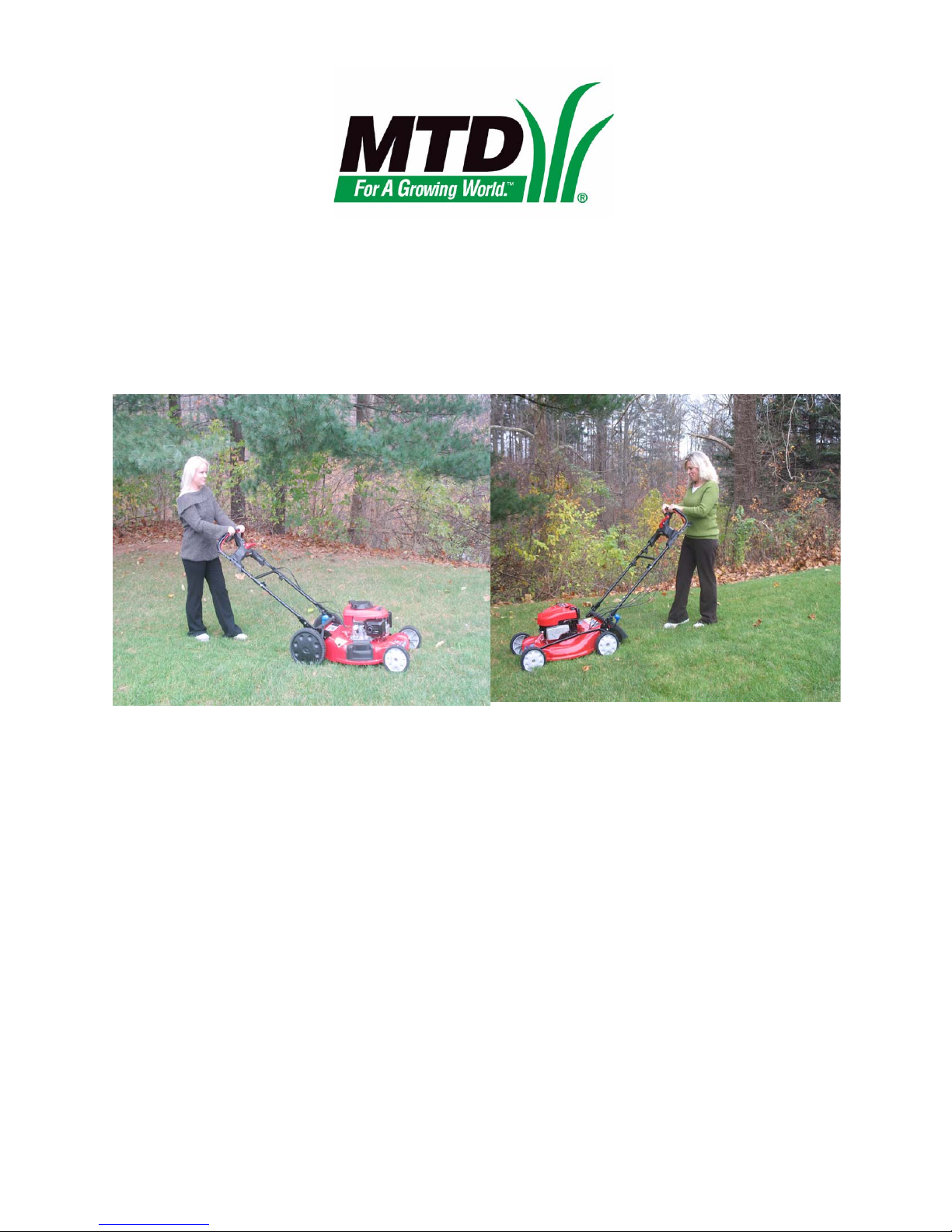
The 830 and 860 Series lawn mowers are rear-wheel
drive self-propelled mowers with a unique variable
ground speed feature. They are both capable of mulch-
ing, bagging or side-discharging grass clippings. Both
mowers have a 21” (53cm) cutting swath.
NOTE: This manual was prepared using pre-
production mowers. The information contained
in the manual is true at the time of writing, but
the equipment may change without notice.
NOTE: This manual is intended to help profes-
sional technicians become acquainted with
newly introduced equipment, so that they can do
their jobs faster, better, and more easily.
If the user of this manual lacks tools or expertise
necessary to safely perform the tasks described,
they should seek the assistance of a trained pro-
fessional.
NOTE: As should be standard operating proce-
dure for any professional, test the operation of
the mower after any repair work, before return-
ing it to service.
CAUTION: Disconnect and ground the spark
plug wire whenever there is a risk of injury from
rotating parts. Working on the cutting blade or
drive system are two examples of situations that
could place a technician at risk.
CAUTION: Take measures to avoid the creation
of a fire hazard when working around equipment
that would normal contain fuel:
• Drain and store fuel in safe containers.
• Clean any fuel spills immediately.
• Avoid exposing fuel to heat sources or open
flame.
NOTE: Replace any worn or damaged fasten-
ers. If a lock washer or bellville washer has lost
its tension, replace it. If the locking feature of a
self-locking nut has worn, replace the nut, or
install it using releasable thread-locking com-
pound such as LoctiteTM 242 (blue).
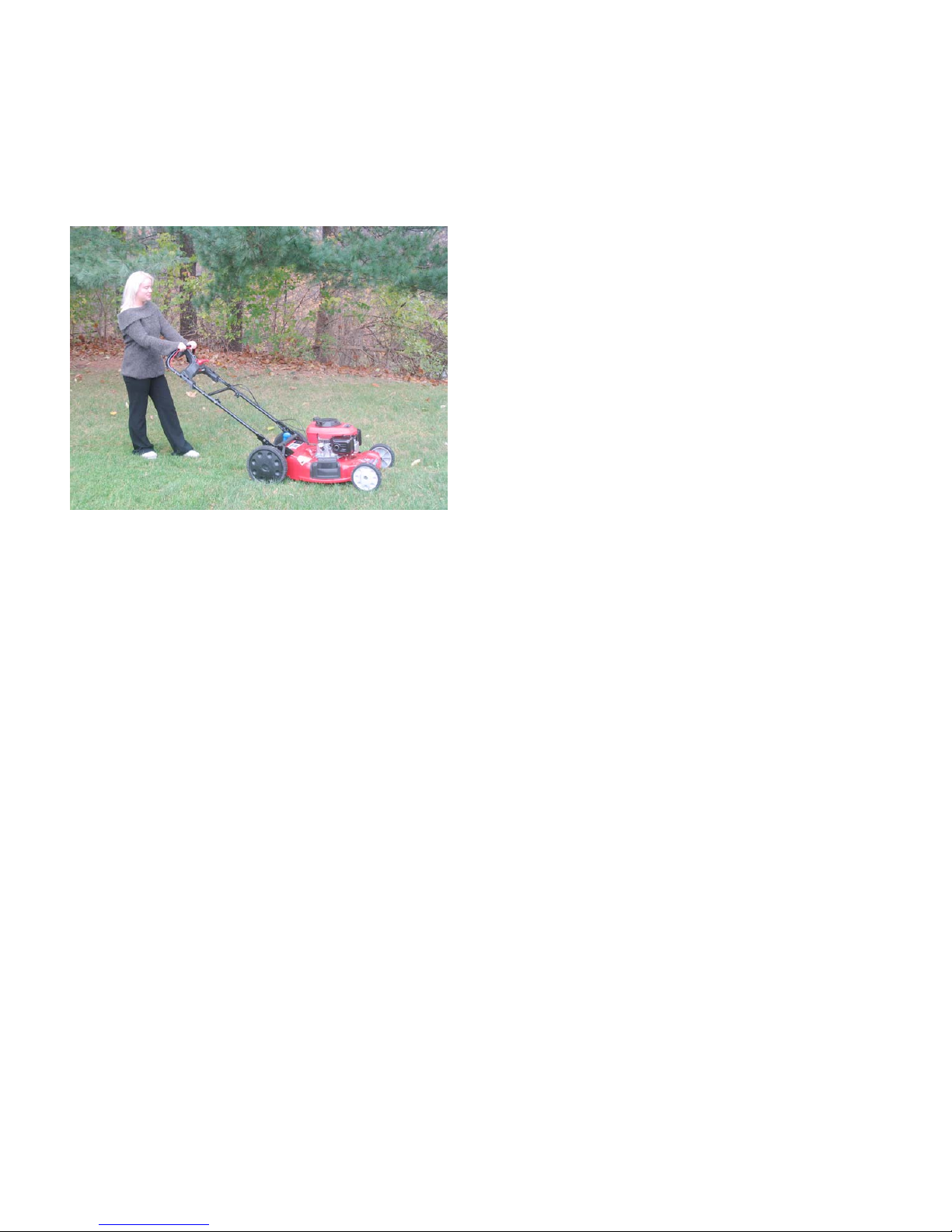
830 series
The 830 series is identified by and eleven digit model
number, e.g.: 12A-83X-XXX.
“12” indicates that it is a self-propelled mower,
“A” identifies the first generation of the model series.
“A” may be followed by an engine identifier.
The “X”s will be style and retailer identifiers. Engines
from different manufacturers may be used on different
models. The models depicted here are in Troy-Bilt liv-
ery, but similar models may be produced in different
lines and for different retailers. See Figure 1.1.
Figure 1.1
CHAPTER 1: INTRODUCTION
www.mymowerparts.com
For Discount White Outdoor Parts Call 606-678-9623 or 606-561-4983