MTD WOLF Alpha 95.165 H User manual

jqa=mêçÇìÅíë=^âíáÉåÖÉëÉääëÅÜ~Ñí=√=p~~êÄêΩÅâÉå=√=dÉêã~åó
C 17
FORM NO. 769-12192


1
2
3
4
5
6
7
C
B
CCCCCC
A
CCCCC
B
C
C
A
B
B
B
ab
ab
C
C
C
B
A
A
A
A
A
B
C D
F
A
B
C
U
P
Q
S
R
T
I
D
O
N
M
L
E
G
H
K
J

EFG
2
3
1
2
1
3
a
bb
G H
I J
LM
K
N
a
ab

100%
50%
0%
OP
QR
UV
W
Y
ST
X


EN
FR
DE
NL
IT
ES
SV
DA
NO
FI
PT
EL
HU
PL
English ............................. 8
(Original operating instructions)
Français ............................. 27
(Notice d’instructions d’origine)
Deutsch ............................. 47
(Originalbetriebsanleitung)
Nederlands ........................... 67
(Originele gebruiksaanwijzing)
Italiano ............................. 87
(Istruzioni per l’uso originali)
Español ............................. 107
(Instrucciones de funcionamiento originales)
Svenska ............................. 127
(Originalbruksanvisning)
Dansk ............................. 146
(Originale driftsvejledning)
Norsk ............................. 165
(Originale driftsanvisningen)
Suomi ............................. 184
(Alkuperäinen käyttöohjekirja)
Português ............................ 203
(Instruções de serviço originais)
Ελληνικά............................. 223
(Αυθεντικές οδηγίες χειρισμού)
Magyar ............................. 243
(Eredeti üzemeltetési útmutató)
Polski ............................. 263
(Oryginalna instrukcja obsługi)

8
Content
EN
Meaning of the symbols
Warning!
Read the instruction manual before
assembly and using for the rst time!
Caution! Bystanders
Do not allow any other persons to enter
the danger area.
Warning! Rotating blades
Risk of injury posed by rotating blades
or parts
Warning! Rotating blades
Keep hands and feet away from rotating
parts. Keep hands and feet away from
underneath the mower.
Caution! Projectile debris
Debris picked up by the mower may be
ejected at high speed.
Warning! Risk of tipping over
Do not operate the device on slopes with
an incline above 20%.
Danger ! Unintended activation
Before working on the device, pull the
spark plug connector. Keep hands and
feet away from rotating parts.
Danger ! Risk of explosion
Content
Meaning of the symbols......................................... 8
For your safety....................................................... 9
Safety instructions ................................................. 10
Intended use.......................................................... 13
Identication plate.................................................. 13
Safety equipment................................................... 13
Assembly............................................................... 14
Operating elements ............................................... 16
Putting into use...................................................... 16
Operation............................................................... 16
Indicator panel (model-dependent, optional)......... 20
Servicing................................................................ 22
Disassembly / assembly and conguring the
cutting mechanism................................................. 24
Storage.................................................................. 24
Transport ............................................................... 24
Troubleshooting..................................................... 25
Motor information................................................... 26
Warranty ................................................................ 26
CE Declaration of Conformity................................ 26
Environmentally-friendly disposal.......................... 26

9
For your safety
EN
Warning! Risk of injury posed by bat-
tery acid
Caution!
Wear protective goggles.
Danger ! Fire, sparks, naked ames
and smoking forbidden!
3E
Attention!
Do not dispose of used batteries with
domestic waste.
Danger ! Unintended activation
Before working on the device, remove
the ignition key. Pay attention to the
notes in these operating instructions.
Attention!
Do not step on the cutting mechanism.
Warning! Hot surface
Caution!
Remove the battery before
tipping the device over.
Warning!
Do not exceed the following
maximum values when us-
ing a trailer:
Max. slope: 14 %
Max. bearing load on the trailer coupling: 25 kg
Max. trailer load (trailer and cargo): 180 kg
Note
Always keep these symbols in a legible
condition. Replace damaged or illegible
symbols.
For your safety
Danger levels of warning information
The following danger levels are used in this
instruction manual to indicate potentially dangerous
situations:
DANGER !
A dangerous situation is highly likely and, if
the measures are not followed, will result in
severe injury and even death.
WARNING !
A dangerous situation may occur and, if
the measures are not followed, will result in
severe injury and even death.
CAUTION !
A dangerous situation may occur and, if
the measures are not followed, will result in
slight or minor injuries.
Attention!
A possibly harmful situation may occur which if not
avoided will result in property damage.
Safety information content
DANGER !
Type and source of the danger!
ÂConsequences of non-observation
¾Measure for preventing the danger

10
Safety instructions
EN
Safety instructions
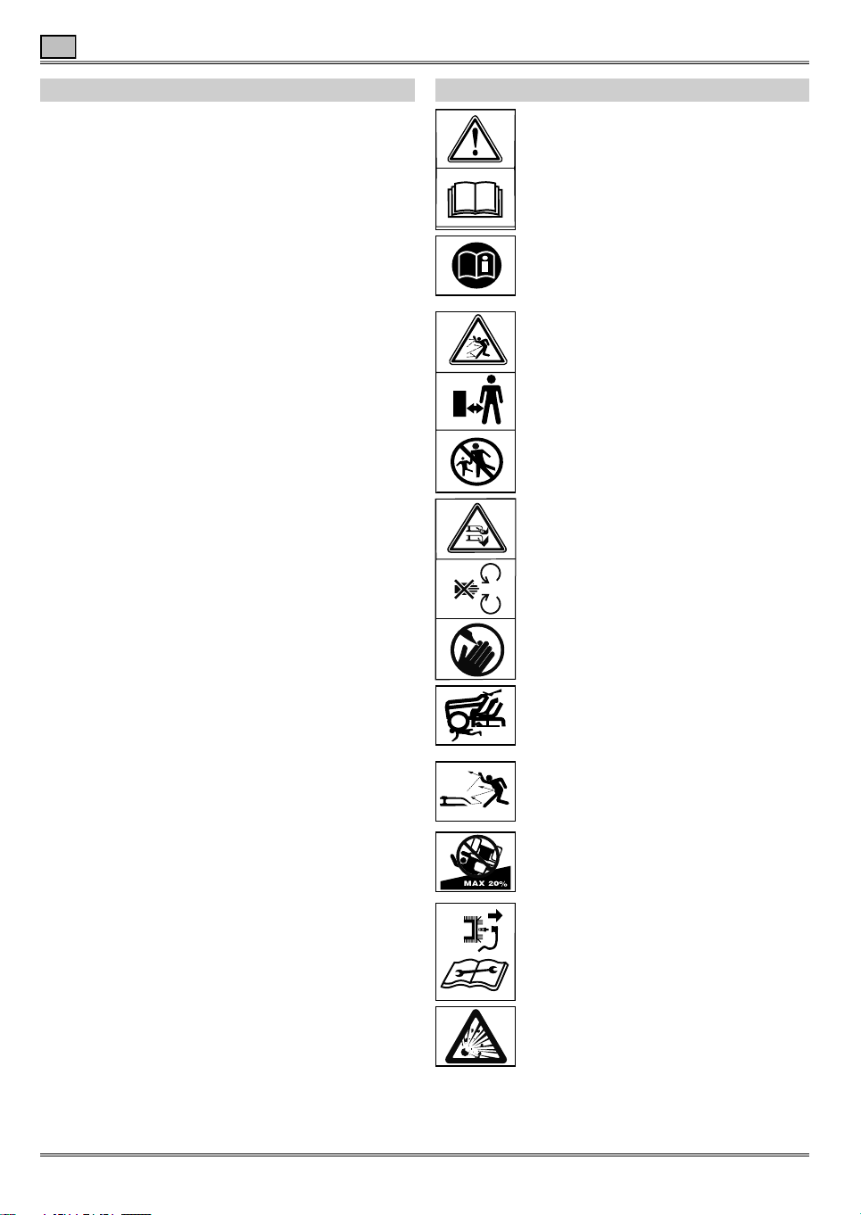
Before using your device for the rst
time, read this instruction manual
carefully and observe the instructions.
Keep this instruction manual for later use or
subsequent owners.
ÎBefore using for the rst time, you must read the
safety information!
Failure to observe the instruction manual and
the safety instructions can result in damage to
the device and danger for the operator and other
persons.
ÎFamiliarise yourself with all the controls and their
proper application.
ÎAll persons involved with set-up, operation and
servicing of the device must have appropriate
qualications.
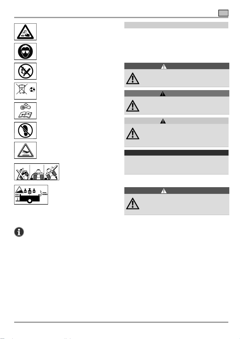
The making of unauthorised changes or
conversions is not permitted
Do not make any changes to the device nor convert
it to produce other devices. Such changes may
result in personal injury and malfunctions.
ÎRepairs to the device must only be performed
by trained persons who have been instructed to
do so. When doing so always use original spare
parts. This ensures that the safety of the device is
maintained.
Information symbols in this manual
The signs and symbols in this manual should help
you to use the manual and device quickly and
safely.
Note
Information to ensure the most effective
and practical use of the mower.
ÎStep
Requires you to perform an action.
3Action result
This is the result of a sequence of steps.
[1]Item number
Item numbers are indicated in the text by square
brackets [ ].
AIllustration label
Illustrations are numbered with letters and
identied in the text.
1Step number
The dened sequence of steps is numbered and
identied in the text.
Protection of yourself and others
¾For safety reasons, children or persons who
are not familiar with the instruction manual
and operation of the device, must not use it.
¾Persons under the age of 16 must not operate
the device or perform other work on it, such
as maintenance, cleaning or conguration.
The minimum age of the user may be dened by
local or national legislation.
¾Persons operating the device must not
be under the inuence of intoxicants (e.g.
alcohol, drugs or medication).
¾Do not use the device without appropriate
training or if you are suffering from tiredness
or illness.
¾Be careful and do not reach into the cutting
blade area.
¾Remember that the mower operator is
responsible for any accidents with other
persons or their property.
¾The device can be used by persons with
limited physical, sensory or mental abilities
or lack of experience and / or knowledge,
insofar that they are supervised or have
received instructions about the safe handling
of the device and understand the associated
dangers.
¾Do not operate the device when there are
people (especially children) or animals in the
immediate vicinity.
¾Ensure children do not play with the device.
¾Stop moving if you notice that persons
(especially children) or animals are nearby.
¾Always wear sturdy shoes and long trousers
as well as other appropriate personal
protective equipment (safety glasses, ear
defenders, safety gloves etc.) when working
with the device. The wearing of personal
protective equipment minimises the risk of injury.
Do not wear loose clothing or clothing with
hanging cords or belts. Working without hearing
protection can lead to hearing loss.

11
Safety instructions
EN
Before use
¾Before starting work, make sure you are
familiar with the device, its controls and how
it is operated.
¾Check that all fastening components (nuts,
bolts, screws, etc.) are tight to ensure safe
operation of the device.
¾Only operate the device in a technically
perfect condition. Never modify the motor
settings which have been preset at the factory.
Any damage must be repaired by a qualied
expert or workshop.
¾Remove any adjustment tools or spanners
before switching the device on. Injuries could
be caused by a tool left in the activity area of the
rotating cutting tools.
¾Never use a device with damaged or missing
guards.They must be repaired or replaced by a
qualied expert or workshop.
¾Never use the machine without protective
devices, and do not remove them! The
protective equipment forms part of the device.
¾Never use the device with defective or
damaged safety equipment. Safety equipment
is designed for your protection and must always
be in functioning order. You must never make any
modications to safety equipment or bypass their
functions.
¾Check the grass collector for damage and
correct mounting.
¾Before mowing, make sure that the lawn is
free from branches, stones, wire etc. and look
out for such objects the whole time when
mowing. Objects can be seized and hurled away.
¾Visually inspect the cutting blade and its
fasteners to check that they are not blunt,
damage or deformed.
¾Attach trailers or add-on devices as per
instructions. Add-on devices, trailers, ballast
weights and lled grass collector inuence driving
performance, especially steering capability,
braking capability and the propensity for tipping
over.
When in use
¾Do not mow lawns with grass longer than 25
cm in height.
¾Drive carefully. Reduce speed before making a
turn.
¾Do not use the device in an explosive
environment, where there are inammable
liquids, gases or dusts. The device may create
sparks, which could ignite the dust or vapours.
Avoid naked ames, sparks and do not smoke.
¾Take extra care if you are mowing or driving
backwards. To prevent accidents, drive slowly
and take glances at the ground behind you while
doing so.
¾Only adjust the cutting height with the
motor switched off and the cutting tool at a
standstill.
¾Never remove the grass collector or the
optional deector while the motor is running.
¾Never drive over gravel or pavements with the
cutting mechanism running. You may be hit by
stones!
¾Do not mow overgrown, dry grass (e.g.
pasture grass) or dry piles of leaves. Do not
park the device on dry grass or leaves. Risk of
re from contact with the hot exhaust and when
dried grass or leaves accumulate on the hot
mower.
¾Pay attention to trafc when working on roads
or when crossing them. The device is not
intended for use on public roads.
¾Never empty the grass collector when the
cutting mechanism is running. Either yourself
or others could become injured by cut material or
objects which are ung out when emptying the
grass collector.
¾Take particular care when opening and
closing the grass collector as there is a risk
of crushing.
¾Keep sufcient distance when mowing
by boundary areas, such as next to steep
inclines or pits, beneath trees, or by bushes
and hedges.
¾If a foreign object (like a stone) comes into
contact with the cutting mechanism, or if
the device starts to vibrate unusually, switch
the motor off immediately. Inspect the device
for damage before continuing operation. If
necessary, take it to a workshop.
Safety instructions

12
Safety instructions
EN
¾Never stand in front of the grass ejector
openings.
¾Switch off the motor and remove the ignition
key before freeing blockages or removing
obstructions in the discharge duct.
Mowing on steep slopes
¾Do not mow or drive on slopes with an incline
greater than 20%.
¾Always mow up and down slopes and not
across them. Do not turn on slopes. Working
on slopes is dangerous. The device could tip over
or slip.
¾Always approach slopes as gently as possible
and brake carefully. When driving backwards,
keep the motor engaged and drive slowly. Take
extra care when changing direction.
¾Do not use any heavy add-on devices on
slopes of more than 9%, such as transport
trailers or lawn rollers.
After use
ÎIf you leave the seat of the device, always
switch the motor off. Always remove the ignition
key and engage the parking brake.
¾Ensure that ventilation slots are free from dirt.
¾Let the motor cool down before storing the
device.
Prior to working on the device
¾Prior to all work on the device, protect
yourself from injury by
- Switching the motor off.
- Removing the ignition key.
- Engaging the parking brake.
- Waiting until all moving parts have come to a
complete standstill.
- Wait until the motor has cooled down.
- Remove the spark plug connector from the motor
so that unintentional motor starts are prevented.
General safety instructions
¾Never let the motor run in buildings or poorly
ventilated areas. Risk of fatality from carbon
monoxide poisoning!
¾Spare parts and accessories must meet the
requirements specied by the manufacturer.
Therefore use only original spare parts/
accessories or spare parts/accessories approved
by the manufacturer. During replacement, always
observe the supplied tting instructions. Using
spare parts or accessories not approved by the
manufacturer may pose an elevated safety risk.
¾Repairs must only be performed by a qualied
expert or workshop.
¾Never allow any passengers on the device.
The device is not approved for passenger
transport.
¾This device is intended for the care of grass
and lawn areas in private households. The
device must not be used for purposes other than
those intended because of the risk of bodily injury
to the user or other persons.
¾Only use the device in daylight or under
bright articial light. Keep your work area clean
and well lit.
¾Always have all maintenance work performed
punctually to keep the device in a safe
operating condition.
¾The exhaust and motor get hot and can cause
burns. Do not touch!
¾Only use the device in dry weather
conditions. Keep the device away from rain or
damp. The device can slip on wet grass due to
reduced ground traction.
¾Do not use the device when raining or there is
a risk of lightning.
¾Never drive with the motor hood open.
¾Handle fuel carefully. Fuel and petrol fumes
are explosive and fuel is readily ammable.
Never refuel the device with the motor running or
hot. Only refuel the device out in the open. Only
store fuel in containers approved for that purpose
and never within the proximity of sources of heat
(e.g. furnaces or boilers). Damaged exhausts,
fuel tanks or tank caps must be replaced.
¾Do not start the motor of fuel has overown.
Push the device away from the area
contaminated with fuel and wait until the fuel
vapours have evaporated.
¾In order to prevent a risk of re, keep the
motor, the battery and the fuel tank free of
grass and discharging oil.
¾Also pay attention to the notes in the motor
manual.
Safety instructions

13
Intended use
EN
Intended use
This device is intended for use
- As a lawn tractor for mowing grass areas of a
house or gardens.
- With accessories explicitly approved for this lawn
tractor.
- In accordance with the descriptions and safety
notes provided in these operating instructions.
Any other use is classed as an unintended use.
Improper use invalidates the warranty and results in
a rejection of all responsibility by the manufacturer.
The user is liable for damage to third parties and
their property.
Unauthorised modications to the device absolves
the manufacturer of liability for any damages that
result.
This device is not approved for operation on public
roads, nor for transporting people.
Identication plate
Position
The identication plate is located under / in front of
the driver's seat.
Note
The identication is considered as a docu-
ment. It must never be altered or obliterated.
/
9
8
5
3
4
1
10
6
7
2
Structure
1 Guaranteed sound level
2 Manufacturer
3 Model name
4 Model number
5 Serial number
6 Weight
7 Power
8 Motor rotation speed in rpm
9 CE label
10 Year of manufacture
Safety equipment
Grass collector S
CAUTION !
Contact with the cutting blade and objects
hurled out
ÂRisk of injury
¾Only operate the device with the
grass collector attached or an optional
deector.
Safety locking system
The safety locking system enables the starting of the
motor only when
- The driver has taken his/her seat on the device.
- The brake pedal is pushed down / the parking
brake is in the parking position.
- The accelerator pedal is at "N".
- The cutting mechanism is switched off; i.e.: PTO
switch to position "O/Aus/Off" (PTO = Power Take-
Off)
The safety locking system prevents mowing without
the grass collector attached or without the optional
deector attached (automatic motor or cutting
mechanism deactivation).
In devices with a PTO switch (electromechanical
PTO), the safety locking system automatically
switches off the cutting mechanism once the
operator leaves the seat with the cutting mechanism
activated; irrespective of whether the parking brake
was activated beforehand.
In devices without an OCR function or with a
deactivated OCR function, the safety locking
system prevents reversing with the cutting
mechanism activated (automatic shutdown of motor
or cutting mechanism).
ÎPrior to reversing on devices with PTO, switch off
the cutting mechanism using the PTO switch.
Note on devices with a PTO switch
In the case of automatic shutdown through
the safety locking system (e.g. reversing or
leaving the seat with the cutting mechanism
activated), rst switch the switch off, and
then back on again, to release the clutch
lock (PTO).

14
Assembly
EN
Direction specications
The direction specications on the device (e.g. left,
right) are always based on facing forwards.
Assembly
Note
In order to be able to move the tractor, the
gear release lever must be in the appropri-
ate position. See the section "Operation –
Pushing the device".
Attaching the seat B
ÎRemove the screws and nuts on the seat sup-
port 1.
ÎFix the seat support to the mounting bracket 2
using the previously removed screws and nuts.
ÎPress the adjustment lever or open the adjustment
screw (depending on the model) 3.
ÎPush the seat into a position in which you have
good access to the seat connector 4.
ÎAttach the connection cable to the seat con-
nector 5.
ÎRetighten the seat adjustment screw (depending
on the model).
Note
The seat is equipped with a seat-occupation
sensor, which belongs to the safety locking
system. The device can thus only be oper-
ated correctly when the connection cable is
correctly inserted into the seat connector.
Attaching the upper dashboard covering
(model-dependent) Ca
ÎInsert the tabs (A) of the dashboard covering [B]
into the openings of the dashboard support [C] 1.
ÎPress them forwards until the stop 2.
ÎCheck the covering ts rmly.
Attaching the motor hood covering
(model-dependent) Cb
ÎPlace the motor hood covering with the re-
cesses [A] on the retaining brackets [B] on the
motor hood 1.
ÎPress the covering backwards until the stop 2.
ÎPress both clips [C] slightly upwards to lock the
cover 3.
ÎCheck the covering ts rmly.
Attaching the steering wheel D
ÎRemove the cover cap [1] (design-dependent) on
the steering wheel.
ÎPlace the spacer [6], the spring [5] and the
washer [4] onto the steering shaft [7].
ÎPlace the steering wheel on the steering shaft.
ÎFasten the steering wheel using the washer [3]
and the screw [2] (tightening torque: 25-28 Nm).
Note
Put on the washer [3] with the bulge facing
upwards.
ÎPut on the cover cap [1].
Note
After disassembling the steering wheel
screw, this must be replaced with a new
original screw and screw retention.
Attaching the front bumper
(model-dependent) E
ÎRemove the four screws from the front bumper.
ÎFasten the front bumper to the tractor frame (inner
side) using the previously removed four screws.
Putting the battery into operation
DANGER !
Risk of re, explosion and corrosion posed
by battery acid and gases from battery acid
¾Battery acid is corrosive. Clean all device
parts immediately which are sprayed with
battery acid.
¾Do not smoke, keep burning and hot
objects at a distance.
¾Charge batteries only in well-ventilated
and dry areas.
¾Possible short circuits when working on
the battery. Do not place any tools or
metallic objects on the battery.

15
Assembly
EN
DANGER !
Risk of poisoning and injury posed by
battery acid
¾Wear protective goggles and protective
gloves.
¾Avoid skin contact with battery acid.
¾If battery acid is sprayed in your face
or eyes, wash the area exposed
immediately with cold water and seek
medical attention.
¾If you have swallowed battery acid, drink
lots of water and seek medical attention.
¾Store batteries out of the reach of
children.
¾Never tip batteries over, as battery acid
may run out.
¾Return any leftover battery acid to your
dealer or a disposal company.
Attention!
¾Pay attention to the assembly sequence for
connecting and disconnecting the battery.
¾Put the battery into operation only with the
battery pole cover (in the form of a cover ap on
the positive terminal, or as a complete battery
protection cover, depending on the design)
attached.
Note
The battery is located in the battery compart-
ment on the rear of the device F. To open
the battery compartment, remove the two
tommy nuts and take off the cover.
Installation Ga
ÎFirst connect the red cable (+ / positive pole) 1.
ÎThen connect the black cable
(- / negative pole) 2.
ÎAttach the battery pole cover.
Removal
ÎDetach the battery pole cover.
ÎFirst disconnect the black cable (- / negative pole).
ÎThen connect the red cable (+ / positive pole).
In the event of a maintenance-free / sealed
battery (type 1) being supplied
(Battery without sealing plugs)
WARNING !
Electrolyte uid may even discharge from
sealed batteries
ÂRisk of injury and re
¾Avoid tipping the battery over
ÎPrior to initial commissioning, charge up the bat-
tery using a 12-Volt battery charger (maximum
charge current 6 Amperes) for one to two hours.
ÎOnce charging is over, rst detach the mains con-
nector of the charger.
ÎThen disconnect the battery (also refer to the
charger's operating instructions).
Attention!
¾Pay attention to the notes in the operating
instructions for the charger.
In the event of an unlled battery being delivered
(type 2)
(Battery with sealing plugs)
ÎRemove the sealing plugs from the battery
cells Gb.
ÎFill each cell slowly with battery acid up to 1 cm
below the ll opening.
ÎLeave the battery standing for 30 mins.
ÎCheck the acid level, and top up with battery acid
if necessary.
ÎPrior to initial commissioning, charge up the bat-
tery using a 12-Volt battery charger (maximum
charge current 6 Amperes) for one to two hours.
ÎOnce charging is over, rst detach the mains con-
nector of the charger.
ÎThen disconnect the battery.
ÎAttach the sealing plugs to the battery.
ÎInstall the battery in the device.
ÎFirst connect the red cable (+), then the black
cable (-).
Attention!
¾Pay attention to the notes in the operating
instructions for the charger.
Note
Later only ll the battery with distilled water
(inspect every two months).
Attaching the grass collector
ÎRead and observe the separate operating instruc-
tions 'Grass collector'.

16
Operating elements
EN
Operating elements
Overview A
A Ignition lock (model-dependent)
1 Ignition lock with key for turning
2 Ignition lock with key for pressing (also with a Bluetooth
service function on certain models)
B PTO switch (model-dependent)
C Forward-drive pedal
D Reversing pedal
E Cutting height adjustment lever
F Gear release lever
G Discharge chute
H Fill level sensor for grass collector (model-dependent)
I Trailer coupling
J Battery compartment
K Seat adjustment lever
L Storage compartment with cup holder, dependent on model
with optional 12 volt socket
M Pedal for differential lock (model-dependent)
N Switch for parking brake / cruise control
O Indicator panel (model-dependent)
P Choke (model-dependent)
Q Braking pedal
R Tank level indicator
S Throttle / choke (model-dependent)
T Fuel tank
U Steering wheel (not visible)
Putting into use
Prior to each operation
Check:
• All protective equipment
• Motor oil level (see motor manual)
• Tank ll level
• Tyre pressure
• Side coverings, add-on devices, air lter area
for damage and mowing residue
Checking the tank and oil level
Note
The motor is already lled with oil at the fac-
tory. Please check and top up if necessary.
• Refuel with unleaded petrol P.
• Fill the fuel tank to a maximum of 2 cm below
the bottom edge of the ller neck.
• Seal the fuel tank shut tightly.
• Check the oil level T. The oil level must be
between the "Full/Max" and "Add/Min" markings
(also refer to the motor manual).
Checking tyre pressure
Note
For reasons of manufacture, tyre pressure
may be higher than required.
ÎCheck tyre pressure and correct it when required.
Front 0.9 bar
Rear 0.7 bar
Adjusting the driver's seat L
ÎPull the lever and adjust the seat La.
or
Release the adjusting screw, set the seat and
tighten the adjusting screw once again Lb.
Adjusting the cutting mechanism wheels U
The cutting mechanism wheels must be at the
lowest cutting mechanism setting, always at least
6–12 mm above the ground. The cutting mechanism
wheels are not designed to bear the weight of the
cutting mechanism. They are merely designed to
compensate for bumps in the ground.
ÎAlways space the cutting mechanism wheels
evenly.
Operation
Attention!
¾Also pay attention to the notes in the operating
instructions for the motor.
Note
Pay attention to national / municipal regula-
tions governing hours of use; enquire at your
local authority if necessary.
Engaging / disengaging the parking
brake AN
ÎTo engage the parking brake, step down fully on
the brake pedal AQand press the switch N.
ÎTo disengage the parking brake, step on the brake
pedal AQuntil the switch N is released.
Attention!
¾Always engage the parking brake before leaving
the device.

17
Operation
EN
Setting the motor speed Q
You can set the motor speed with innite variability
using the throttle.
Fast motor speed =
Slow motor speed =
Starting the motor
Note
The choke Mis used for starting the device
when the motor is cold. Some models do
not have a choke. The motor prepares itself
automatically for the relevant start process.
ÎOpen the fuel tap (if present, see motor manual).
ÎSit yourself down on the driver's seat.
ÎSwitch off the cutting mechanism.
ÎEngage the parking brake.
ÎSet the throttle to .
ÎIf the motor is cold, pull the choke / set the
throttle to .
ÎActuate the ignition key H (depending on the igni-
tion lock):
ÎInsert the ignition key into the ignition lock [3].
ÎTurn the ignition key to until the motor starts
running. Release the ignition key.
ÎThe ignition key stays in the normal position.
(Mowing in a forward direction)a.
or
ÎInsert the ignition key [3] in the ignition lock
and press it downwards for at least 1.5 seconds
until the motor starts running.
ÎRelease the ignition key.
3The ignition key stays in the normal position.
(Mowing in a forward direction)b.
Note
A start attempt should last a max. of 5
seconds. Wait 10 seconds until the next
attempt.
Note
The OCR function must not be activated
during the start process (see section "OCR
function).
ÎReset the choke or the throttle until the motor runs
smoothly.
Stopping the motor
ÎSet the throttle to the mid-throttle point.
ÎLet the motor run for approx. 20 seconds.
ÎSet the ignition key (model-dependent) to Ha
or press the ignition key downwards and release it
Hb.
ÎRemove the ignition key.
Driving
WARNING !
Risk of sudden start-up, sudden stopping
and driving with excessive speed
ÂRisk of accident
¾Start up slowly and brake slowly.
¾Do not drive at excessive speed.
¾Never change the driving direction
without rst bringing the device to a stop.
ÎRelease the parking brake by stepping down fully
on the brake pedal and then releasing it again.
ÎTo drive away, step on the accelerator pedal.
Note
The further down on the accelerator pedal
you step, the faster the device will move.
Driving with cruise control N
ÎPress the switch while driving.
3The forward speed selected at that point in time
(but not the maximum speed) is maintained.
3You can take your foot off the accelerator pedal.
ÎTo deactivate cruise control, step on the brake
pedal / accelerator pedal until the switch is re-
leased again.
Stopping the device A
ÎTake your foot off the accelerator pedal C or D.
ÎStep on the brake pedal Quntil the device comes
to a standstill.
Note
When you step on the brake pedal, you
simultaneously switch the cruise control off.

18
Operation
EN
Switching the cutting mechanism on/off I
With the PTO switch, the cutting mechanism is
switched on and off through an electromechanical
coupling.
ÎTo switch the cutting mechanism on, pull the PTO
switch .
ÎTo switch the cutting mechanism off, press the
PTO switch .
Note on the PTO switch
In the case of automatic shutdown through
the safety locking system (e.g. reversing
with the cutting mechanism activated), the
switch must rst be switched off and then
back on again, to release the clutch lock.
Adjusting the cutting height J
ÎTo set the cutting height, actuate the cutting height
adjustment lever.
Note
"4" is the largest possible cutting height
(approx. 10 cm); the cutting mechanism is
located right at the top.
"Lo/1" is the smallest cutting height (ap-
prox. 2.5 cm); the cutting mechanism is
located right at the bottom.
Mowing
CAUTION !
Objects hurled out (cut grass, stones, etc.)
ÂRisk of injury
¾Only empty the grass collector when the
cutting mechanism is switched off.
¾Only operate the device with the
grass collector attached or an optional
deector.
Attention!
¾If a foreign object (like a stone) comes into
contact with the cutting mechanism, or if the
device starts to vibrate unusually, switch the
motor off immediately.
¾Inspect the device for damage before continuing
operation. If there is damage, do not continue
to use the device, and have it repaired by a
workshop prior to next use.
¾Do not activate the cutting mechanism when
grass is long.
ÎStart the motor as specied.
ÎSet the throttle to .
ÎSwitch on the cutting mechanism and lower it.
ÎRelease the parking brake by stepping down fully
on the brake pedal and then releasing it again.
ÎTo drive away, step on the forward-drive pedal.
Notes on mowing
Do not mow wet grass. Drive slowly at maxi-
mum motor speed.
Mowing on tall or wet grass may lead to
uneven grass accumulation / blockages in
the discharge chute.
Notes on mowing
Depending on the model, the device may
have a ll level indicator for the grass col-
lector. The ll level sensor Ymeasures the
extent to which the grass collector is lled
during mowing. When the grass collector is
full, an acoustic signal sounds and, depend-
ing on the model, the cutting mechanism
automatically, simultaneously switches itself.
The grass collector must then be emptied
prior to further mowing. The sound signal is
only deactivated after emptying the grass
collector.
Setting the fill level sensor Y
WARNING !
Risk of injury
¾Only make adjustments to the ll level
sensor when the motor is switched
off, the parking brake is engaged, the
ignition key is removed and the grass
collector has been detached.
The length of the ll level sensor can be modied
(multiple locking positions) and thus set to the
consistency of the grass cuttings. In this process,
the degree of lling of the grass collector is
inuenced at the same time.
ÎTo shorten the length, push the ll level sensor in
further.
3The sound signal is triggered later; the cutting
mechanism is deactivated later, depending on the
model.
Note
Ideal for short, very dry grass cuttings.
ÎTo extend the length, pull the ll level sensor out
further.
3The sound signal is triggered earlier; the cutting
mechanism is deactivated earlier, depending on
the model.
Note
Ideal for lush, damp grass.

19
Operation
EN
OCR function (model-dependent) H
The ignition lock is tted with an OCR function,
which offers you user-controlled mowing, even when
reversing.
Notes on mowing
Only use the OCR function if absolutely
necessary.
ÎStart the motor.
ÎTurn the ignition key [3] anti-clockwise from
normal position to reverse-mowing position
and press the switch [1]a.
or
Press the switch [1]bfor 3 seconds.
3The indicator lamp [2] lights up. You can now mow
both when moving forwards and when reversing.
ÎTo terminate the OCR function, turn the ignition
key clockwise to the normal position .
or
Press the switch [1] bdownwards and then
release it.
3The indicator lamp goes out.
Notes on the ignition lock Ha
The OCR function is switched off automati-
cally once the key is turned to the normal
position or the motor is shut down (stop
position or shutdown of the motor through
the safety lock system).
Information about the ignition lock Hb
The OCR function is switched off automati-
cally once the OCR switch is pressed, the
motor is shut down or the safety lock system
automatically switches the motor or the cut-
ting mechanism off.
Mulching
Mulching is when the grass is cut into small pieces
(approx. 1 cm) during mowing and left lying there.
This means the lawn retains many nutrients.
ÎAsk your dealer for appropriate accessories for
mulching.
Lawn care tips
A lawn comprises various grass types. If you mow
more frequently, the growth of strongly-rooting
grasses is favoured resulting in rm turf.
If you mow only rarely, the growth of tall grasses and
other weeds (e.g. clover, daisies) is encouraged.
To ensure you lawn grows healthily and uniformly,
without any lines, the cutting stripes must always
overlap by a couple of inches/several centimetres.
- The normal height of the grass is 40–50 mm.
Cut approximately one third of the overall height
as soon as the lawn has reached a height of
60–70 mm.
- Do not cut the lawn shorter than 45 mm as other-
wise the turf can be damaged during dry periods.
- Cut long grass in stages until normal height is
reached.
Switching on the headlights (model-
dependent) R
ÎTo switch on the headlights, set the switch to
"ON".
3The headlights light up while the motor is running.
Note
The headlamps switch on and off automati-
cally on models without a light switch.
Note
Depending on the model, the headlights stay
lit up for approx. 10 seconds after the motor
has shut down and then switch themselves
off automatically.
Switching the differential lock on and off
(model-dependent) A
WARNING !
An activated differential lock has a strong
inuence on the steering performance of
the device.
ÂRisk of injury and damage to the device
¾Only use the differential lock when
absolutely necessary; e.g. on difcult
terrain.
¾Only activate the differential lock when
the device is at a standstill.
¾Do not use the differential lock on paved
pathways or downhill.
¾Only drive straight when the differential
lock is activated.
¾Only drive slowly with the differential lock
activated.

20
Indicator panel (model-dependent, optional)
EN
With the differential lock activated, power is
transmitted to both rear wheels. The differential lock
intervenes if different wheel speeds are detected.
ÎStop the device.
ÎTo activate the differential lock, step on the
pedal M.
ÎTo deactivate the differential lock, take your foot
back off the pedal M.
Note
If the differential lock does not release im-
mediately, reduce the speed of the device or
bring the device to a standstill.
Parking the device
ÎStop the device.
ÎSwitch off the cutting mechanism.
ÎSet the throttle to the centre position.
ÎBring the cutting mechanism into the highest posi-
tion.
ÎSwitch the motor off after 20 seconds.
ÎEngage the parking brake.
ÎRemove the ignition key.
Pushing the device
Note
The gear release lever is located between
the rear panel and the device's right rear
wheel.
Devices with differential lock Ka
ÎSwitch the motor off.
ÎDisengage the parking brake.
ÎPull the gear release lever out fully.
3You can now push the device.
Note
Before you start the motor, press the gear
release lever back in fully.
Devices without differential lock Kb
ÎSwitch the motor off.
ÎDisengage the parking brake.
ÎPress the gear release lever in fully.
3You can now push the device.
Note
Before starting the motor, pull the gear
release lever out again fully.
12-volt socket (model-dependent) X
The socket is used for connection of a 12 volt
battery charger or connection of miscellaneous 12
volt devices.
Note
Observe the corresponding information of
the battery charger or the 12 volt devices
that are to be connected.
Indicator panel (model-dependent,
optional)
Note
The indicators only come on when the motor
is running.
Note
If an oil change and air lter maintenance
arise simultaneously, the oil change indicator
lights up rst, then the air lter indicator.
Depending on the design, the indicator panel may
consist of the following elements:
Type 1 Oa in conjunction with the ignition
lock Ha
Operating hours counter
When the ignition is activated, the battery voltage is
briey displayed. This then changes to the operating
hours indicator.
The operating hours are always counted, except
when the ignition key is at "Stop" or is withdrawn.
Maintenance indicator
Note means: The total operating hours are
displayed.
– – – Oil change
ÎChange the motor oil immediately (see the oper-
ating instructions for the motor).
This indicator appears every 50 operating hours for
a period of 2 hours.
Table of contents
Languages:
Other MTD Lawn Mower manuals