MTD Yard Machines 31A-020-900 User manual

YARD
Operator's Manual
Electric
Snow Thrower
31A-020-900
IMPORTANT: READ SAFETY RULES
AND INSTRUCTIONS CAREFULLY
P/N 6096-MD2301 (2)
PRINTED IN CHINA

Rules for Safe Operation
Operating Instructions
Maintenance Instructions
Troubleshooting
Pages 2-7
Page 8-9
Pages 10-11
Page 12
Specifications
Parts List
Notes
Manufacturer's Limited Warranty
Page 12
Page 13
Page 14
Page 15

The purpose of safety symbols is to attract your atten-
tion to possible dangers. The safety symbols, and their
explanations, deserve your careful attention and under-
standing, The safety warnings de not by themselves
eliminate any danger. The instructions or warnings they
give are not substitutes for proper accident prevention
measures,
SYMBOL MEANING
Indicates
SAFETY ALERT: danger,
warning or
ca.ution. Attention is required in order to
avoid serious personalinjury. May be used
in conjunction with other symbols or pic-
tographs.
NOTE: Advises you of information or instructions vital to
the operation or maintenance of the equipment.
Read the Operator's Manual(s) and follow all warnings
and safety instructions.
Failure to do so can result in serious injury to the
operator and/or bystanders.
FOR QUESTIONS, CALL 1-800-668-1238
SYMBOL MEANING
DANGER: Failure to obey a
safety warning will
result in serious injury to yourself or to oth-
ers. Always follow the safety precautions to
reduce the risk of fire, electric shock and
persona njury.
Failure to obey a
WARNING: safety warning can
result in injury to yourself and others.
Always follow the safety precautions to
reduce the risk of fire, electric shock and
personal injury.
Failure to obey a
CAUTION: safety warning may
result in property damage or personal injury
to yourself or to others. Always follow the
safety precautions to reduce the risk of fire,
electric shock and personal injury.
= IMPORTANT SAFETY INSTRUCTIONS •
READ ALL INSTRUCTIONS
BEFORE OPERATING
When using the
WARNING" unit,please read
safety rules instructions before operating
the unit in order to ensure the safety of the
operator and any bystanders. Please keep
these instructions for later use.
•Carefully inspect the area before starting the unit.
Remove all debris and hard or sharp objects such as
glass, wire, etc.
• Clear the area of children, bystanders, and pets. At a
minimum, keep all children, bystanders, and pets out-
side a 50 feet (15m.) radius; there still may be a risk to
bystanders from thrown objects. If you are approached,
stop the unit immediately.
•Read the instructions carefully. Be familiar with the
controls and proper use of the unit.
* Do not operate this unit when tired, ill or under the
influenceof alcohol, drugs or medication.
•Children must not operate the unit. Teens must be
accompanied and guided by an adult,
• All guards and safety attachments must be installed
properly before operating the unit.
•Inspect the unit before use. Replace damaged parts.
Make sure all fasteners are in place and secure.
Replace parts that are cracked, chipped or damaged in
any way. Do not operate the unit with loose or dam-
aged parts.

PLEASE READ - SAVE THESE
INSTRUCTIONS
When using an electrical appliance, basic precautions
should always be followed to assure maximum safety and
optimum performance. Read this manual before assem-
bling and operating this appliance. Failure to comply with
instructions may result in electrical shock, burns, fire, or
personal injury.
WARNING
TO REDUCE THE RISK OF ELECTRIC
SHOCK, BURNS, FIRE OR PERSONAL
INJURY:
1, FOLLOW ALL SAFETY INSTRUCTIONS tisted in
this manual before/during operation of this snow
thrower.
2, TO REDUCE THE RISK OF ELECTRIC SHOCK this
equipment has a polarized plug (one blade is wider
than the other), This plug will fit in a polarized exten-
sion cord onty one way. Ifthe plug does not fit fully in
the extension cord, reverse the plug. Do not change
the plug in any way.
3. INSPECT UNIT FOR DAMAGE to the housing or
plug. Keep all fasteners tight, Do not use if the trigger
does not turn the unit off properly. Never use unit if
cord or plug has been damaged, the motor or unit
itself is not working as it should or has been dropped,
damaged, left outdoors or dropped in water. Never
operate with any air opening blocked. Keep air open-
ings free of debris that may reduce air flow. Replace
damaged parts that are chipped, cracked or dam-
aged in any way.
4. _DOUBLE INSULATED to help protect against
electric shock. Double insulation construction
consists of 2 separate "layers" of electric insulation.
Appliances built with this insulation system are not
intended to be grounded. As a result, the extension
cord used with your unit can be plugged into any
conventional 120 volt electrical outlet. Normal safety
precautions must be observed when operating an
electrical appliance. The double insulation system is
only for added protection against injury resulting from
a possible internal electrical insulation failure.
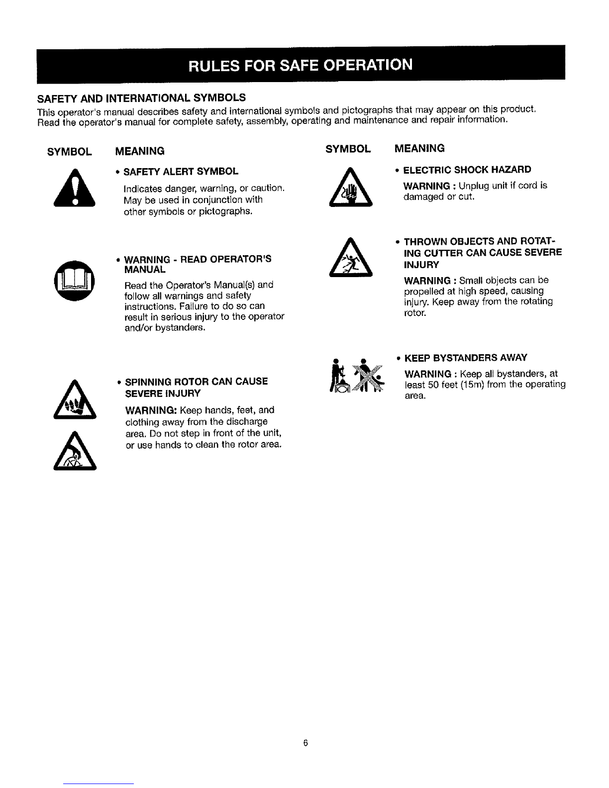
5. When the double insulation symbol (a square within a
square) is used as the oniy marking to identify a unit
as being double insulated, the symbol shall be
defined in the instruction manual.
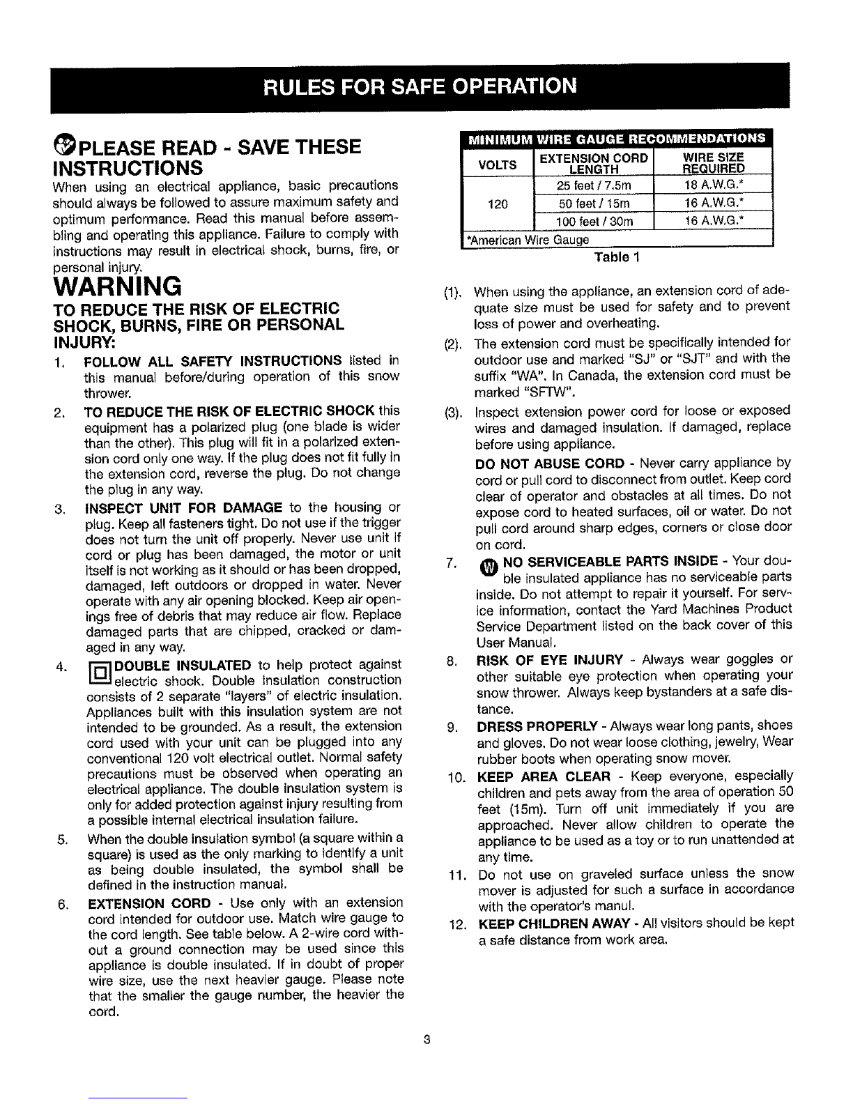
6. EXTENSION CORD - Use only with an extension
cord intended for outdoor use. Match wire gauge to
the cord {ength. See table below. A 2-wire cord with-
out a ground connection may be used since this
appliance is double insulated. If in doubt of proper
wire size, use the next heavier gauge. Please note
that the smalter the gauge number, the heavier the
cord.
I I
EXTENSION CORD WIRE SIZE
VOLTS LENGTH ,, REQUIRED
25 feet /7.5m !8 A.W,G.*
120 50 feet /15m 16A.W,G,*
100 feet/30m 16A.W.G.*
*American Wire Gauge Table 1
(1). When using the appliance, an extension cord of ade-
quate size must be used for safety and to prevent
loss of power and overheating.
(2). The extension cord must be specifically intended for
outdoor use and marked "SJ" or "SJT" and with the
suffix "WA". In Canada, the extension cord must be
marked "SFTW".
(3). Inspect extension power cord for loose or exposed
wires and damaged insulation, if damaged, replace
before using appliance.
DO NOT ABUSE CORD - Never carry appliance by
cord or pull cord to disconnect from outlet. Keep cord
clear of operator and obstacles at all times. Do not
expose cord to heated surfaces, oil or water. Do not
puil cord around sharp edges, corners or close door
on cord.
7. _ NO SERVICEABLE PARTS INSIDE - Your dou-
ble insulatedappliance has no serviceable parts
inside. Do not attempt to repair it yourself. For sew-
ice information, contact the Yard Machines Product
Service Department listed on the back cover of this
User Manual.
8. RISK OF EYE INJURY - Always wear goggles or
other suitable eye protection when operating your
snow thrower. Always keep bystanders at a safe dis-
tance.
9. DRESS PROPERLY - Always wear long pants, shoes
and gloves. Do not wear loose clothing, jewelry, Wear
rubber boots when operating snow mover,
10. KEEP AREA CLEAR - Keep everyone, especially
children and pets away from the area of operation 50
feet (15m). Turn off unit immediately if you are
approached. Never allow children to operate the
appliance to be used as a toy or to run unattended at
any time.
11. Do not use on graveled surface unless the snow
mover is adjusted for such a surface in accordance
with the operator's manul.
12. KEEP CHILDREN AWAY -All visitors should be kept
a safe distance from work area.

13. Wearrubberbootswhenoperatingthesnowmover.
14. Cautionarystatementsregardingtheuseof proper
clothingandfootweaduringoperationstoreducethe
riskofinjurythatmaybecausedbyflyingdebris.
15. Operationofthesnowmoverinthehand-heldposi-
tionisunsafe,exceptinaccordancewiththespecial
instructionsforsuchuseprovidedintheoperator's
manual.
16. WARNING- Thissnowmovershouldbegrounded
whilein useto protectthe operatorformelectric
shock,Topreventelectricshockuseonlywithan
extensioncordsuitableforoutdooruse.
17. EXTENSION CORD - To prevent disconnection of
snow mover cord from the extension cord during
operation.
18, AVOID ACCIDENTAL STARING - Don't carry
plugged - in snow mover with finger on switch, Be
sure switch is off when plugging in.
19. If cord isdamaged in any manner while plugged in,
pull extension cord from wall receptacle.
20. DON'T ABUSE CORD - Never carry snow mover by
cord or yank it to disconnect from receptacle. Keep
cord from heat, oil, and sharp edges,
21. Keep hands away from moving parts.
22. Keep guards in place and in working order,
23. DON'T FORCES SNOW MOVER - It will perform
better and safer at the rate for which it was
designed.
24. DON'T OVERREACH - Keep proper footing and
balance at all times.
25. If the snow mover strikes a foreign object follow
these steps:
i) Stop snow mover,
ii) Inspect for damage.
iii)Repair any damage before restarting and operat-
ing the snow mover.
26. DISCONNECT SNOW MOVER - Disconnect the
snow mover from the power supply when not in use,
before servicing, when changing accessories, and
the like,
27. STORE IDLE SNOW MOVERS INDOORS - When
not in use, snow movers should be stored indoors in
dry, locked-up place - out of reach of children.
28. MAINTAIN SNOW MOVERS WITH CARE - Follow
instructionsfor lubricating and changing acces-
sories.
29. Don't use any other accessory or attachment might
incrase the risk of injury.
WHILE OPERATING
1. Walk, never run.
2. Be sure the snow thrower is not in contact with any-
thing before staring the unit.
3. Stay away from the discharge opening at all times.
Keep face, hands, and feet away from concealed
moving or rotating parts.
4. Be attentive when using the snow thrower, and stay
alert for holes in the terrain and other hidden hazards
or traffic.
5. Do not use on a gravel surface or crushed rock sur-
faces. Use extreme caution when crossing
gravel/crushed rock drives, walks, or roads.
6. Never clear snow from steep slopes.
7. Never attempt to use the snow thrower on a roof or
any steep, inclined, slippery surfaces.
8, Never operate snow thrower without proper guards,
plates or other safety protective devices in place.
9. Never operate the snow thrower near glass enclo-
sures, automobiles, trucks, window wells, dropoffs,
etc. without proper adjustment of the snow discharge
angle. Keep children and pets away.
10. Don't force or overload the snow thrower. The snow
thrower will perform at its best and safest when it is
run at the rate for which it was designed.
11. Never direct discharge towards people or allow any-
one in front of the unit while operating.
12, Wear safety glasses or goggles that are marked as
meeting ANSI Z87.1 standards, and ear/hearing pro-
tection when operating this unit.
I3. Use the unit only in daylight or good artificial light.
14. Avoid accidental starting. Remain in the starting posi-
tion whenever starting the unit. The operator and unit
must be in a stable position while starting.
15. Use the right tool. Only use this too! for the purpose
intended.
16. Do net overreach. Always keep proper footing and
balance.
17. Always hold the unit with both hands when operating.
Keep a firm grip on handles or grips.
18. Keep hands, face, and feet at a distance from all
moving parts. Do not touch or try to stop the rotor
when it is rotating.
19. If the rotor will not rotate freely due to frozen ice, thaw
the unit thoroughly before attempting to operate it
under power.
20. Keep the rotor clear of debris.
21. Never attempt to clear the rotor with the motor run-
ning. Turn the motor off first and unplug the extension
cord.

22, Keepclothingandbodypartsawayfromtherotor.
23. Alwaysstopthemotorwhenclearingsnowisdelayed
orwhenwalkingfromonelocationtoanother.
24. Disengagepowertotherotorwhensnowthroweris
transported or not in use.
25. After striking a foreign object, turn the unit off and
inspect the snow thrower from damage. Unplug the
unit. Repair damage before restarting and operating
the unit.
26. If the unit should start to vibrate abnormally, stop the
unit and check immediately for the cause. Vibratioin
is generally a warning of trouble.
27. Stop the motor and unplug the unit whenever you
leave the operating position, before unclogging the
rotor or discharge vanes, and when making any
repairs, adjustments, or inspections.
28. Use only original equipment manufacturer replace-
ment parts and accessories for this unit. These are
available from your authorized service dealer. Use of
any unauthorized parts or accessories could lead to
serious injury to the user or damage to the unit, and
void your warranty.
29. Do not use the unit in the hand held position. Do not
pick up the unit when it is powered and running. The
unit is designed to travel along the ground.
OTHER SAFETY WARNINGS
1. Be sure to secure the unit while transporting.
2. Store the unit in a dry area, locked up or up high to
preventunauthorized use or damage, out of the reach
of children.
3. Never douse or squirt the untt with water or any other
liquid. Keep handles dry, clean and free from debris.
Clean after each use.
4. If the labels on the unit become defaced or start lift-
ing off, contact your authorized service dealer.
5. Keep these instructions. Refer to them often and use
them to instruct other users. If you loan someone this
unit, also loan them these instructions.
6. Maintain snow movers with care. Follow instructions
for lubricating and changing accessories.
EXPLANATION OF NOTE, WARNING, and
WARRANT'{ SYMBOL
1, A NOTE is used to convey additional information, or
highlight a particular explanation, or to expand a step
instruction.
2. A WARNING identifies a procedure which, if not
undertaken or if improperly done, can result in a seri-
ous personal injury or damage to the unit and/or
both.
3. _ (WARRANTY SYMBOL) serves notice that
unless instructions or procedures are followed, any
damage will void the warranty and repairs will be at
owner's expense. Service other than user mainte-
nance should be performed by a Yard Machines
Authorized Service Center. Damage or conditions
caused by improper maintenance practices which
render this product inoperable will void the manufac-
turer's warranty.
4. FOR WARRANTY OR SERVICE contact the nearest
Yard Machines Authorized Service Center by calling
800# on back cover.
SAVETHESE INSTRUCTIONS

SAFETY AND INTERNATIONAL SYMBOLS
This operator's manual describes safety and international symbols and pictographs that may appear on this product,
Read the operator's manual for complete safety, assembly, operating and maintenance and repair information.
SYMBOL MEANING SYMBOL
*SAFETY ALERT SYMBOL
Indicates danger, warning, or caution.
May be used in coniunction with
other symbols or pictographs.
MEANING
•ELECTRIC SHOCK HAZARD
WARNING : Unplug unit if cord is
damaged or cut.
•WARNING -READ OPERATOR'S
MANUAL
Read the Operator's Manual(s) and
follow all warnings and safety
instructions. Failure to do so can
result in serious injury to the operator
and/or bystanders.
A,* THROWN OBJECTS AND ROTAT-
ING CUTTER CAN CAUSE SEVERE
INJURY
WARNING :Small objects can be
propelled at high speed, causing
injury. Keep away from the rotating
rotor.
•SPINNING ROTOR CAN CAUSE
SEVERE INJURY
WARNING: Keep hands, feet, and
clothing away from the discharge
area. Do not step in front of the unit,
or use hands to clean the rotor area.
•KEEP BYSTANDERS AWAY
WARNING : Keep all bystanders, at
least 50 feet (15m) from the operating
area.

LOCK-OFF
BUTTON
REAR
HANDLE
ON/OFF TRIGGER
ASSIST
HANDLE
CORDRETAINER
PLUG FOR
EXTENSION CORD
ADJUSTABLE
SHAFT
/
/
/
/
ADJUSTMENT RING
AIR OPENINGS
MOTOR HOUSING
BELT CASE COVER
ROTOR
SCRAPER

CONNECT THE CORD
1. Ensure the cord is NOT plugged into a receptacle
before this procedure.
2, Make a loop with 8" - 10" (20 - 25cm) of the end of the
extension cord.
3. Place the loop into the slot (A) under the rear handle
and lock into place on the cord retainer (B) as shown
in Figure 1.
4. Plug the extension cord into the electrical receptacle
in the snow thrower handle.
5, Plug the extension cord intoa receptacle ONLY when
you are ready to operate the snow thrower.
A
B
ADJUST SHAFT LENGTH
1. Loosen the adjustment ring (A) by rotating the ring
clockwise.
2, Adjust the shaft to a height that is comfortable to you.
3. Tighten the adjustment ring (A) by rotating the ring (A)
counter clockwise. (Fig. 2)
POSITIONING THE ASSIST HANDLE
1, Loosen the knob (A) on the assist handle (B). (Fig. 3)
2, Adjust the assist handle to an angle that is comfort-
able to you.
3, Tighten the knob on the assist handle,
Fig. 3
STARTING AND STOPPING
To start the snow thrower, push the button (A) on the side
of the handle grip and squeeze the trigger (B). To stop the
product, release the trigger. (Fig. 4)
NOTE: When properly started, the safety button wiil stay
engaged when holding the trigger, When the trigger is
released, the unit stops and the safety button will disen-
gage.
A
A
Fig, 4
B
Fig. 2

OVERLOAD PROTECTION SWITCH
This unit is equipped with an overload protection switch to
protect the circuit (that the unit is plugged into) from short
circuit overloads.
If the switch pops out.
1. Retease the bail and allow the unit to stop and cool for
a minute,
2. Press the overload switch (A) to reset, Resume oper-
ation. (Fig, 5)
If the switch pops again shortly after the first time:
1, Allow the unti to cool for 15 to 30 minutes,
2, After the unit has cooled, press the overload switch to
reset. Resume operation.
If the switch does not stay in or if it continues to pop out
during operation, take the unit to an autorized service deal-
er for repair,
Fig, 5
TIPS FOR BEST SNOW THROWING RESULTS
1. For the most efficient snow throwing, throw snow
downwind.
2, Slightly overlap each swath you make. (Fig. 6)
_i:i_ii_!:_iiiiiii_i!:_i__ _}_ _;_:,ii?_i_
OPERATING THE SNOW THROWER
1, Start the unit according to the starting instructions,
The depth and weight of the snow governs the forward
speed.
2. Push the unit so that it rides on the scraper.
3. Make sure the power cord is attached to the cord
retainer. The power cord should trail to the side of the
operator.
Fig. 6

SERVICING THE UNIT
Extreme care and knowledge of the system is required
when servicing this unit. Service should be pedormed by
qualified service personnel only. Replacement parts for this
unit must be identicalto the parts they replace, Refer any
repair to an authorized service dealer.
INSPECTING/REPLACING THE DRIVE BELT
When servicing the unit, use only original equipment man-
ufacturer replacement parts. Inspect the drive belt once a
year or every 50 hours of operation, whichever comes first,
for wear. If the drive belt needs to be replaced, use the foL-
lowing instructions.
I_ IAIADI_IIMt'_.- To avoid serious I
vv_"Lm z,zl,,a',z_,,,q, personal injury,
turn off the unit and allow it to cool. Unplug
the unit before you perform any mainte-
nance.
1, Remove the 7 screws (A) from the belt case cover (B)
using a #T20 torx bit or flat blade screwdriver. (Fig. 7)
2, Remove the flange lock nut (C) and remove the 3
screws (D) from the belt case cover (E) using a #T20
Torx hit or flat blade screwdriver. (Fig, 8)
3. Pull the belt tensioner (F) away from the drive pulley
(G). Remove the damaged or broken belt (H) from the
driven pulley (I) and drive pulley inside of the housing.
Discard appropriately. (Fig. 9)
4. Loop the new belt around the drive pulley and driven
pulley (Fig. 8). Pull the belt tensioner (idler arm) away
from the drive pulley to install the belt around the drive
pulley.
NOTE; Make sure the washer is still in pface on the driven
pulley shaft prior to reinstalling the belt case cover.
5. Reinstall the flange lock nut. Torque the nut to 50-100
in° lb (90-11,2 N*m) and reinstall the 3 screws. Torque
all screws to 18-23 in, Ib (20-2.5 Nom).
6. Reinstall the cover with the 7 screws. To make instal-
lation easier, place the narrow part of the cover into
the recess of the housing. Install the top 2 screws,
then push the rest of the cover down into the recess
and over the rotor shaft. Toque all 7 screws to 18-23
in, Ib (20-2.5 N°m)
NOTE: If the flange Iock nut is damaged, do not replace it
with a standard nut. Replace only with an original equip-
ment manufacturer replacement part.
Fig. 7
Fig. 8
10
Fig. 9

REPLACING THE PLATE
Use only original equipment manufacturer replacement
parts,
WAl_lklllkl#__ " To avoid serious I
rtmlmm1%,_, personal injury, J
always turn your unit off and unplug it
before you perform maintenance.
1, Place the unit on the ground or on a work bench,
Position the unit so the vanes and rotor are facing up,
2. Beneath the rotor, locate the 3 screws (A) securing
the plate (B) to the housing. Remove them using a
#T20 Torx bit or flat blade screwdriver. (Fig, 10)
3. Remove the scraper and discard ft approprlatety.
4. The new scraper will snap into place. Once in place,
attach it to the unit by reinstalling the 3 screws,
Fig. 10
CLEANING
WARNING: Toavo .ser o.s
personal injury,
always turn your unit off and unplug it
before you clean or service it.
Use a small brush to clean offthe outside ofthe unit, Do not
use strong detergents, Household cleaners that contain
aromatic oils such as pine and lemon, and solvents such as
kerosene, can damage plastic housing or handle. Wipe off
any moisturer with a soft cloth.
TRANSPORTING
1. Secure the unit while transporting.
2. To move the unit, grasp it by the top and middle front
handles.
A
STORAGE
1, Allow the motor to cool before storing,
2. Store the unit locked up to prevent unauthorized use
or damage.
3. Store the unit in a dry, well-ventilated area,
4. Store the unit out of the reach of children.
11

CAUSE
Unit is unplugged
Trigger lock button or trigger were improperly actuated
Overload protection switch has popped out
ACTION
Check cord to make sure it is plugged into an electrical
outlet
Press in trigger lock button, hold it, and press in trigger
Push it in and follow the starting instructions
CAUSE
Belt is damaged ACTION
Replace the belt, according to inspecting/Replacing the
driver belt
CAUSE
Scraper is worn ACTION
Replace the scraper
If further assistance is required, contact your authorized service dealer
Motor type .................................................................... A. C, 120 Volts Electric
Amperage ..................................................................... 7.5 Amps
clearing Width ................................................................. 12.5" (318mm)
Intake Height .................................................................. 6" (152mm)
Weight ....................................................................... 15 tbs
12

io
ii
12
1
/54
45
46
39
50
36
35
1
2
:3
4
5
6
7
8
9
10
I"L
12
13
14
15
t6
t7
t8
19
2O
21
22
23
24
25
26
27
2B
6022-MD2301
6068-M02301
6134 -MD2301
6198-MD23{}2
6186-MD2301
6SGEBB04-18
6070-MD2301
6037-MD2301
6010-MD2301
6067-MD230l
6129.MD230t
6131-MD2301
6187-MD2_301
6099-MD230t
6017-MD230t
6014-MD2301
614B.MD2301
6250.MD230t
6100,MD25O2
6WFB-04
6200-MD2301
6084-MD2301
6!11-MD2302
6024-MO2301
6004.MD2302
6DB-620301
6004-MD2301
6137-M D2301
SWITCH
HANDLE RtGHT
KNOB
ASSIST HANDLE
ASSIST HANDLE
SCREW
PLUG PiPE
TUBE
SPRING CODE
HOUSING TOP
PiPE
SPOOL
FIXED PLATE
MOTOR
COVER RIGHT
WASHER
SLEEVE
BLADE
PLATE
WASRER
PLATE
MAIN BODY
SHAFT
SPRING
HOLDER BOTI'OM
BEARING
HOLDER TOP
PULLEY 13
NO,
29
30
31
32
33
34
35
36
37
38
39
40
4t
42
43
44
45
46
47
48
49
5O
51
52
53
54
55
Pa_sNo.
6137-MD2302
6t49-MD2301
6072-MD2301
9NAC-OB
6017-MD2302
6SDABB04-20
6WFB-04*12
9WFB-08-13
PULLEY ACTIVE
STRAP
FIXED PLATE
NUT
COVERLEFT
SCREW
WASHER
WASHER
9SKKBYI 0/24-0,5 SCREW
60_ 4=MD2302
6189-MD2301
6078-MD230t
6067-MD2302
6068-MD2302
6SXDZ.06-15O
6272-MD23Ot
6041-MD230t
60t0-MD2304
6032-070-01
6041.61020t
60t4.MO22O3
6139-MD2302
6059-MD2304
6SGEBB04-35
6SDASB3,5*I 8
6183.MC2301
6014-211901
WASHER
WASHER
CAP
HOUSING BOTTOM
HANDLELEFT
SCREW
PROTECTSWITCH
CONNECTOR
WIREASS'Y
BAND, PLASTIC
TERMINAL
WASHER
PLASTIC WASHER
PIPE
SCREW
SCREW
GASKET
WASHER

t4

MANUFACTURER'S LIMITED WARRANTY FOR:
YARD
The limited warranty set forth below is given by MTD
LLC ("MTD") with respect to new merchandise purchased and
used in the United States and Canada, its possessions and
territories.
MTD warrants this product against defects in material and
workmanship for a period of two (2) years commencing on the
date of original purchase and will, at its option, repair or
replace, free of charge, any part found to be defective in
material or workmanship. This Iimited warranty shall only apply
if this product has been operated and maintained in
accordance with the Operator's Manual furnished with the
product, and has not been subject to misuse, abuse,
commercial use, neglect, accident, improper mainlenance,
alteration, vandalism, theft, fire, water or damage because of
other peril or natural disaster. Damage resulting from the
installation or use of any accessory or attachment not
approved by MTD for use with the product(s) covered by this
manual will void your warranty as to any resulting damage,
This warranty is limited to ninety (90) days from the date of
original retail purchase for any MTD product that is used for
rental or commercial purposes, or any other income-producing
purpose will void the warranty.
HOW TO OBTAIN SERVICE: Warranty service is available,
WITH PROOF OF PURCHASE THROUGH YOUR LOCAL
AUTHORIZED SERVICE DEALER. To locate the dealer in
your area, please check for a listing in the Yellow Pages or
contact the Customer Service Department of MTD LLC by
calling 1-866-747-9816 or writing to P.O. Box 361131,
Cleveland OH 44136-0019 or if in Canada call 1-800-668-
1238. No product returned directly to the factory will be
accepted unless prior written permission has been extended
by the Customer Service Department of MTD LLC.
This limited warranty does not provide coverage in the
following cases:
A. Drive Belt.
g. MTD does not extend any warranty for products sold or
exported outside of the United States of America and
Canada, its possessions and territories, except those sold
through MTD's authorized channels of export distribution.
MTD reserves the right to change or improve the design of any
MTD Product without assuming any obligation to modify any
product previously manufactured.
No implied warranty, including any implied warranty of
merchantability or fitness for a particular purpose, applies
after the applicable period of express written warranty
above as to the parts as identified. NO other express
warranty or guaranty, whether written or oral, except as
mentioned above, given by any person or entity, including
a dealer or retailer, with respect to any product shall bind
MTD. During the period of the Warranty, the exclusive
remedy is repair or replacement of the product as set
forth above. (Some states do not allow limitations on how
long an impfied warranty lasts, so the above limitation may not
apply to you.)
The provisions as set forth in this Warranty provide the
sole and exclusive remedy arising from the sales. MTD
shall not be liable for incidental or consequential loss or
damages including, without limitation, expenses incurred
for substitute or replacement lawn care services, for
transportation or for related expenses, or for rental
expenses to temporarily replace a warranted product,
(Some states do not allow limitations on how long an implied
warranty lasts, so the above limitation may not apply to you.)
in no event shall recovery of any kind be greater than the
amount of the purchase price of the product sold. Alteration of
the safety features of the product shall void this Warranty. You
assume the risk and liability for loss, damage, or injury to you
and your property and/or to others and their property arising
out of the use or misuse or inability to use the product.
This limited warranty shall not extend to anyone other than the
original purchaser, original lessee or the person for whom it
was purchased as a gift.
How State Law Relates to this Warranty; This warranty
gives you specific legal rights, and you may also have other
rights which vary from state to state.
To locate your nearest service dealer dial 1-866-747-9816 in
the United States or 1-800-668-1238 in Canada.
MTD LLC
P.O. Box 361131
Cleveland, OH 44136-0019
!5

YARD
Manuel de Utilisation
D_neigeuse
Electrique
31A-020-900
IMPORTANT: LISEZ LES RI_GLES ET
CONSIGNES DE SI_CURITI_ SOIGNEUSEMENT
P/N 6096-MD2301 (2)
FABRIQU# ik CHLNA

Consignes de s6curit6
Instructions pour montage
Instructions de mantenimiento
D6pannage
Caract_ristiques
Pages 18-23
Pages 24-25
Pages 26-27
Page 28
Page 28
Liste des pi_ces Page 29
Notes Page 30
Garantie Iimit6e du fabricant pour Page 31
17

Les Symbotes de securite attirent votre attention sur
des dangers potentiels. Ces symboles et leurs details
explicatifs meritent que vous les lisiez et compreniez
bien. Les avertissements de securit6 ne peuvent 6viter
les dangers de par eux-m_mes. Les consignes ou
mises en garde qu'ils donnent ne remplacent pas des
mesures preventives appropriees contre les accidents.
SYMBOLE SIGNIFICATION
f f
ALERTE DE SECURITE"
indique un danger, un avertissement ou une
mise en garde. Soyez vigilant afin d'eviter toute
blessure grave. Ce symbole peut 6tre combine
&d'autres symboles ou pictogrammes.
NOTE: Advises you of informationor instructions vital to 1[_'
the operation or maintenance of the equipment.
Read the Operator's Manual(s) and follow all warnings
and safety instructions.
Failure to do so can result in serious injury to the
operator and/or bystanders.
FOR QUESTIONS, CALL 1-800-668-1238
SYMBOLE SIGNIFICATION ....
DANGER: le non-respect d'un
avertissement peut
causer dommages materiels ou blessures
graves pour tous. Respectez les consignes
de securite afin de reduire tes risques
d'incendie, d'etectrocution et de blessures.
AVERTISSEMENT: le
non-respect d'un avertissement peut causer
dommages materiels ou blessures graves
pour tous. Respectez les consignes de
securit6 afin de reduire les risques d'incendie,
d'electrocution et de blessures.
MISE EN GARDE: lenon-
respect d'un avertissement peut causer
dommages materiels ou bfessures graves
pour tous. Respectez toujours les consignes
de securite afin de reduire les risques
d'incendie, d'electrocution et de blessures.
. IMPORTANTES CONSIGNES DE SI CURITI:!: •
LISEZ TOUTES LES INSTRUCTIONS
AVANT UTILISATION
AVERTISSEMENT :
Lorsque vous utilisez I'appareil, veuillez tire
les instructions quant aux regles de secu-
rite avant utilisation afin d'assurer la secu-
rite de I'utilisation et de son entourage.
Veuitlez conserver ces instructions pour une
utilisation ulterieure.
*Lisez les instructions avec attention. Familiarisez-vous
avec les commandes et la bonne utilisation de I'ap-
pareil.
• N'utilisez pas cet appareil si vous ¢tes fatigue, ou sous
I'influence d'alcool, de drogues et autres m6dicaments.
• Les enfants ne doivent pas utiliser I'appareil. Les ado-
lescents doivent etre accompagnes et guides par un
adulte.
• Toutes ies protections et pieces de securite doivent
etre installees oorrectement avant d'utiliser I'appareil.
Inspectez I'appareil avant utilisation. Remplacez les
pieces endommagees. Assurez-vous que toutes les fix-
ations sont en place. Remplacez les pieces fissurees,
ebrechees ou endommagees de quelque fa?on que ce
soit. N'utilisez pas l'appareil avec des pi¢ces desser-
tees ou endommag6es.
lnspectez minutieusement la zone avant de com-
mencer & utiliser I'appareil. Enlevez tousles debris et
les objets durs ou pointus tels que le verre, les fils, etc.
Eloignez les enfants, l'entourage et les animaux
domestiques de la zone. Au minimum, tenez les
enfants, votre entourage et les animaux domestiques
hors d'un rayon de 50 pieds (15m.) ; il reste toujours un
risque de projection pour votre entourage. Si on vous
approche, arretez immediatement I'appareil.
18

LIRE ET CONSERVER CES
INSTRUCTIONS
Lorsqu'un appareil _lectrique est utilis_, des pr6cautions
_l_mentaires doivent toujours _tre prises pour assurer une
s_curit_ maximum et une performance optimale. Lire cette
Notice avant d'assembler et d'utiliser cet appareil. Ne pas
se conformer aux instructions peut causer des secousses
61ectriques, des b_lures, un incendie ou des btessures
corporelles.
AVERTISSEMENT
POUR REDUIRE LES RISQUES DE
BROLURES, D'INCENDIE, DE SECOUSSES
I_LECTRIQUES OU DE BLESSURES :
1, RESPECTER TOUTES LES MESURES DE
S_CURITI_ figurant dana cette Notice avant et durant
l'utilisation du coupe-herbe.
2. POUR REDUIRE LES RISQUES DE SECOUSSES
_LECTRIQUES, cet _quipement est muni d'une fiche
polaris_e (une broche est plus large que I'autre).
Cette fiche ne peut _tre branch_e que dans un sens
et que clans une prise de courant polaris6e. Si la fiche
ne peut pas 6tre enfonc_e & fond dans la prise de
courant, inverser le sens de la fiche. Ne jamais modi-
fier la fiche de t'appareil.
3, INSPECTER L'APPAREIL /_. LA RECHERCHE DE
DOMMAGES qu'auraient pu subir te carter, le cordon
_lectrique ou _la fiche. Toutes tes fixations doivent
_tre bien serr6es. Ne pas utiNser !'appareil si la
g&chette ne permet pas de I'arreter ad_quatement.
Ne jamais utiliserI'appareil si le cordon _lectrique ou
la fiche est endommag_, si le moteur ou le coupe-
herbe lul-meme ne fonctionne pas correctement ou
s'il est tomb_, s'il a _t6 endommag6, laiss6 & I'ex-
t#rieur ou plong6 clans I'eau. Ne pas utillser I'appareit
si les trous de ventilation sont bouch_s. Toujours
enlever les d_bris qui risqueraient de limiter la circula-
tion de I'air par les trous de ventilation. Remplacer les
pi#ces endommag_es qui sont 6br6ch_es, cass_es
ou qui ont _t_ endommag_es d'une maniere ou d'une
autre et qui risqueraient d'etre projet_es et causer de
graves blessures. Garden le couteau de coupeur
aigu.
4. r_ DOUBLE ISOLATION pour prot_ger I'utilisateur
des risques de secousses 61ectriques. La double
isolation consiste en deux <<couches>>d'isolant #lec-
trique. Les appareils construits avec ce type d'isola-
tion ne sent pas con£us pour #tre mis & la terre. Par
consequent, le cordon prolongateur utilis6 avec le
coupe-herbe peut 6tre branch_ dans n'imperte quetle
prise de courant de 120 volts. Des mesures de s_cu-
rit6 _16mentaires doivent toujours 6tre prises
lorsqu'un appareil _tectrique est utilis_. La double iso-
lation constitue seutement une protection suppl_men-
taire en cas de d_faillance de l'isolant interne.
19
,
,
Quand le symbole double d'isolation (un carr6 dana
un carte) est utilis_ comme la seule marque pour
identifier une unit6 comme est double isol_, le sym-
bole sera d_fini dans le manuel d'instruction.
CORDON PROLONGATEUR - Ne brancher cet
appareil que dans un cordon prolongateur con?u pour
usage ext_rieur et d'un calibre ad_quat en fonction de
sa lengueur. Voir le tableau ci-dessous. Un cordon
prolongateur & 2 conducteurs ne poss6dant pas de
connexion & la terre peut _tre utilis6 6tant donn6 que
cet appareil est & double isolation. Si I'on n'est pas st3r
du calibre du cordon prolongateur & utiliser, utiliser un
cordon prolongateur de calibre imm_diatement
sup_rieur. I1est ¬er que plus le num_ro du calibre
est petit plus le cordon prolongateur est gros.
TENSION
120
III._ll III[l] l_!-t I] ::1[I'#_lII_i1:1
LONGUEUFIDU
CORDON
25 pieds/7,5m
50 pieds/15m
100 pieds/30m
iI :I _1=1111ll=_llI_Ih'_llj_=l
CALIBRE DE FIL
REQUIS
18 A.W,G2
16 A.W,G.*
16 A,W,G.*
*American Wire Gauge (CALIBRE AMERtCAIN)
Tableau I
(1). Un cordon prolongateur de diametre appropri6 dolt
etre utilis6 pour _viter les pertes de puissance et la
surchauffe de I'appareil.
(2). Le cordon prolongateur dolt 6tre sp6cialement con£u
pour usage ext_rieur et porter la mention <<SJ,> ou
<<SJT>>et le suffixe ,<WA>>.Au Canada, le cordon pro-
Iongateur doit porter la mention <<SFTW,>.
(3). S'assurer que le cordon prolongateur ne comporte
pas de ills d_nud_s ni desserr_s et que I'isolant n'est
pas endommag_. En cas de dommages, remplacer le
cordon prolongateur avant d'utiNser I'appareil.
NE PAS MALTRAITER LE CORDON - Ne jamais
transporter I'appareil par le cordon electrique ni tirer
sur le cordon _lectrique pour d_brancher !'appareih Le
cordon _lectrique dolt toujours 6tre tenu & 1'6cart de
i'ep6rateur et des obstacles. Ne pas exposer le cordon
_lectrique & des surfaces chaudes, de I'huNe ou de
I'eau. Ne pas tirer le cordon 61ectrique autour d'angles
vifs, de coins et veiller & ne pas le coincer dans une
porte en la fermant.
7, t_ AUCUNE PIECE INTERNE N'EST RI_PARABLE
PAR UUTILISATEUR - Cet appareil a double
isolation ne comporte aucune piece interne reparable
par I'utilisateur. Ne pas essayer de le reparer soi-
m6me. Pour tout renseignement concernant I'entre-
tien, s'adresser A un Centre de r_paration Yard
Machines dont le numero figure sur la couverture
arri_re de cette Notice d'utilisation.
This manual suits for next models
1
Table of contents
Languages:
Other MTD Snow Blower manuals