MTS Sensors Temposonics G Series User manual

Temposonics®
Absolute, Non-Contact Position Sensors
G-Series Handheld Programmer
for analog sensors
Instruction Manual
Part No. 253 853
(replacement for part no. 253 294)

Temposonics® G-Series
Handheld Programmer
MTS Sensors I 2I
Operating the G-Series analogue handheld programmer
The G-Series Analogue Output Sensor utilizes one position magnet to
provide a linear position output over the sensor’s active stroke length.
The output values for the beginning of stroke, ‘Setpoint 1’, and the end of stro-
ke, ‘Setpoint 2’, can be programmed for anywhere along the active stroke length
by using the G-Series Analog Handheld Programmer.
Standard factory settings place ‘Setpoint 1’ (Null) and ‘Setpoint 2’ (Span) at the
limits of the sensor’s active stroke range. For example, a sensor ordered with a
4 to 20 mA output, will be factory set to give a 4 mA output at the null
‘‘Setpoint 1’ and a 20 mA output at the span ‘Setpoint 2’.
‘Setpoint 1’ and ‘Setpoint 2’ can be re-positioned for the actual measuring
range needed anywhere within the active stroke length. These adjustments are
easily done, even when the sensor is not directly accessible, by connecting the
G-Series Analog Handheld Programmer to the sensor’s integral cable or exten-
sion cable.
Please observe the following operation guidelines when using the G-Series ana-
log handheld programmer:
1. The cable length from the analog sensor to the handheld programmer must
not exceed 45 meters.
2. A minimum of 50 mm is required between ‘Setpoint 1‘ and ‘2‘.
3. The handheld programmer cannot be used for changing the output polarity
for switching between forward-acting and reverse-acting output ranges.
4. Refer to ‘Notes’ on page 2 for additional information.
Reverse
Forward
1-Magnet sensor
Output
value
Electronics
housing
Dead
zone
Setpoint 2
(S )
Setpoint 1
(N ll)
Position
The G-Series sensor has (Green & Red) integrated LEDs that indicate sensor
status, error diagnostics, and programming modes. The various LED codes are
also displayed on the G-Series Analog Handheld Programmer when connected
to the sensor. When the programmer is connected and the power is applied, the
sensor will enter serial programming mode.
When the sensor is in programming
mode (Green Flashing, Red OFF), LEDs
on the programmer will indicate the sen-
sor’s functional status. The programmer
uses the same status codes as the G-
Series sensor except for displaying the
programming mode. To successfully re-
program the sensor’s setpoints, the pro-
grammer must indicate no sensor errors
by displaying (Green ON, Red OFF).
Diagnostic LEDs
Green Red Diagnostic Description
OFF OFF No power to sensor
OFF ON Self-diagnostic error
OFF Flashing IR programming mode
ON OFF Normal sensor function
ON ON Magnet not detected
ON Flashing Missing (external) interrogation
Flashing OFF Serial programming mode
Flashing ON Magnet signal weak
Flashing Flashing Power out of range (high or low)

Temposonics® G-Series
Handheld Programmer
MTS SensorsI 3I
To adjust your programmer settings, perform the following steps:
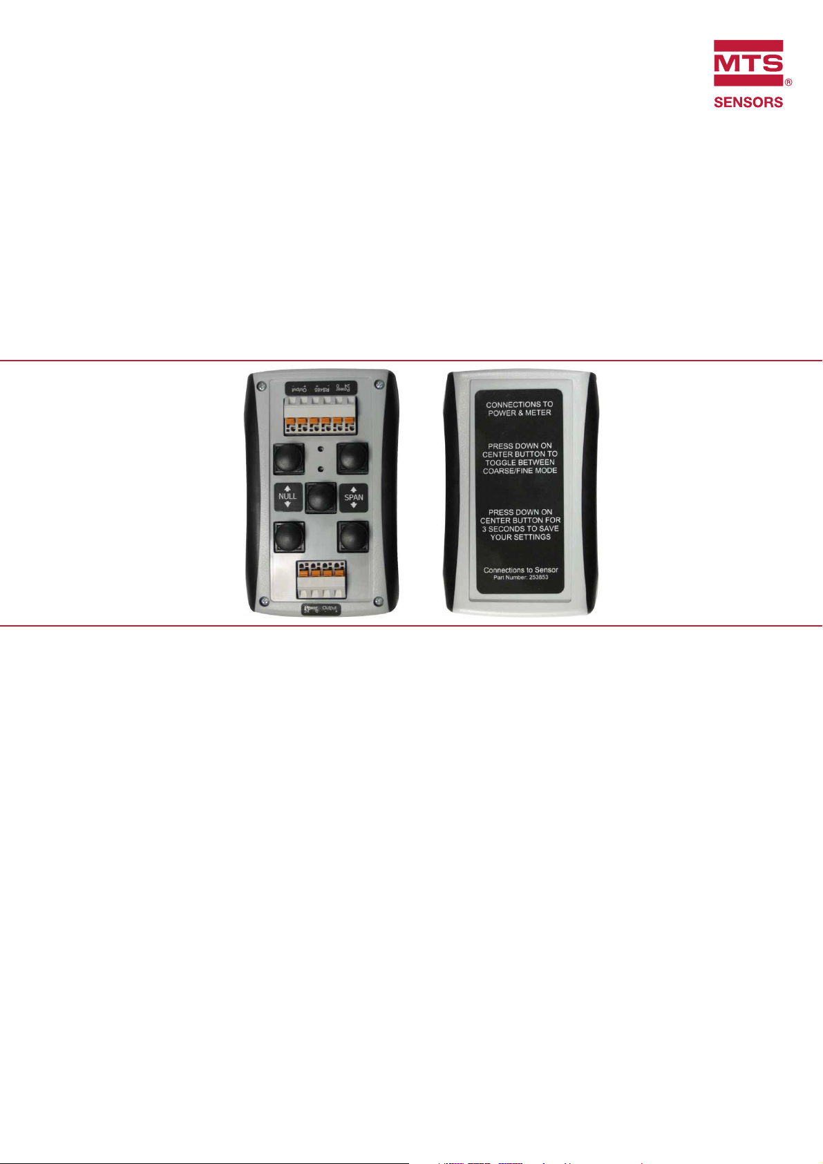
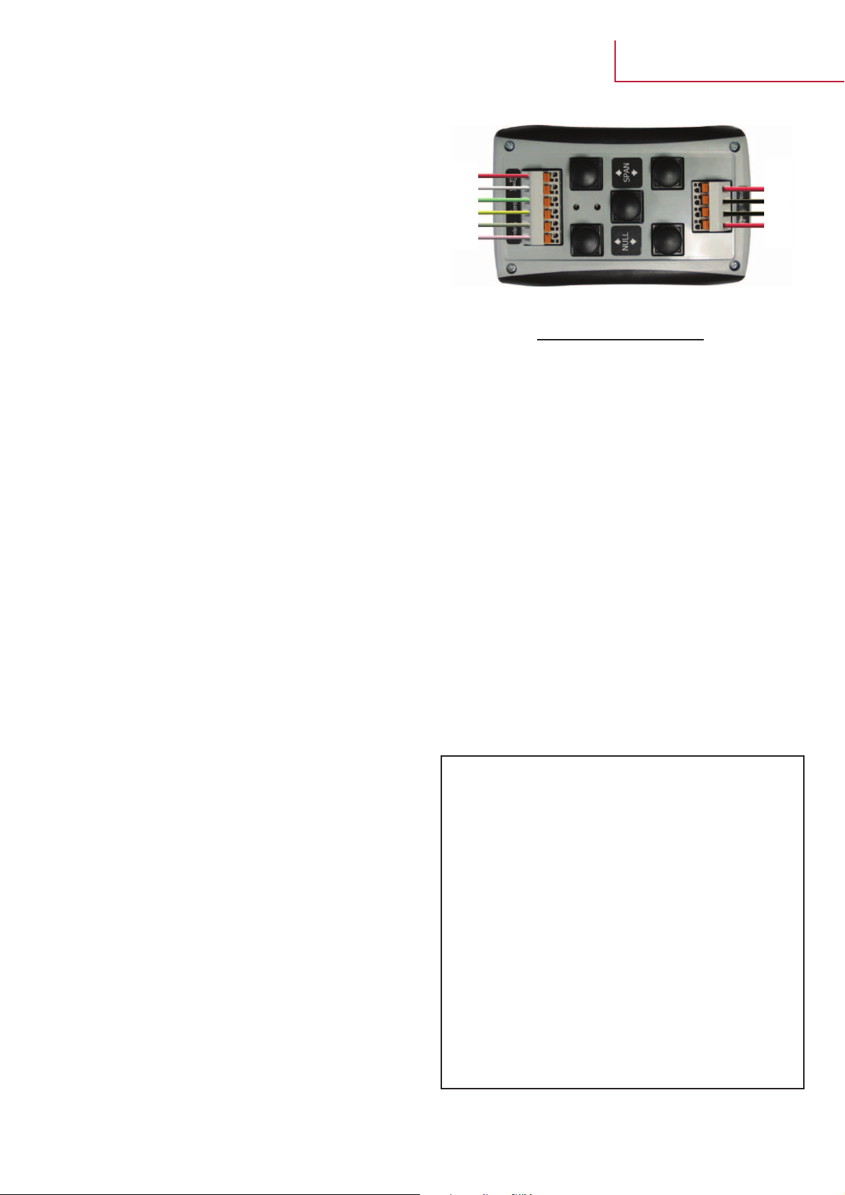
1. Connect the programmer to the sensor’s 6 wires (using an integral cable or
extension cable). The 4 connections at the bottom of the programmer are for
the 24 Vdc power supply and a multimeter. Switch on the power supply. The
sensor will enter serial programming mode, then the sensor’s LEDs will
display Green Flashing, Red OFF. The LEDs on the handheld programmer
must display Green ON, Red OFF to continue programming successfully.
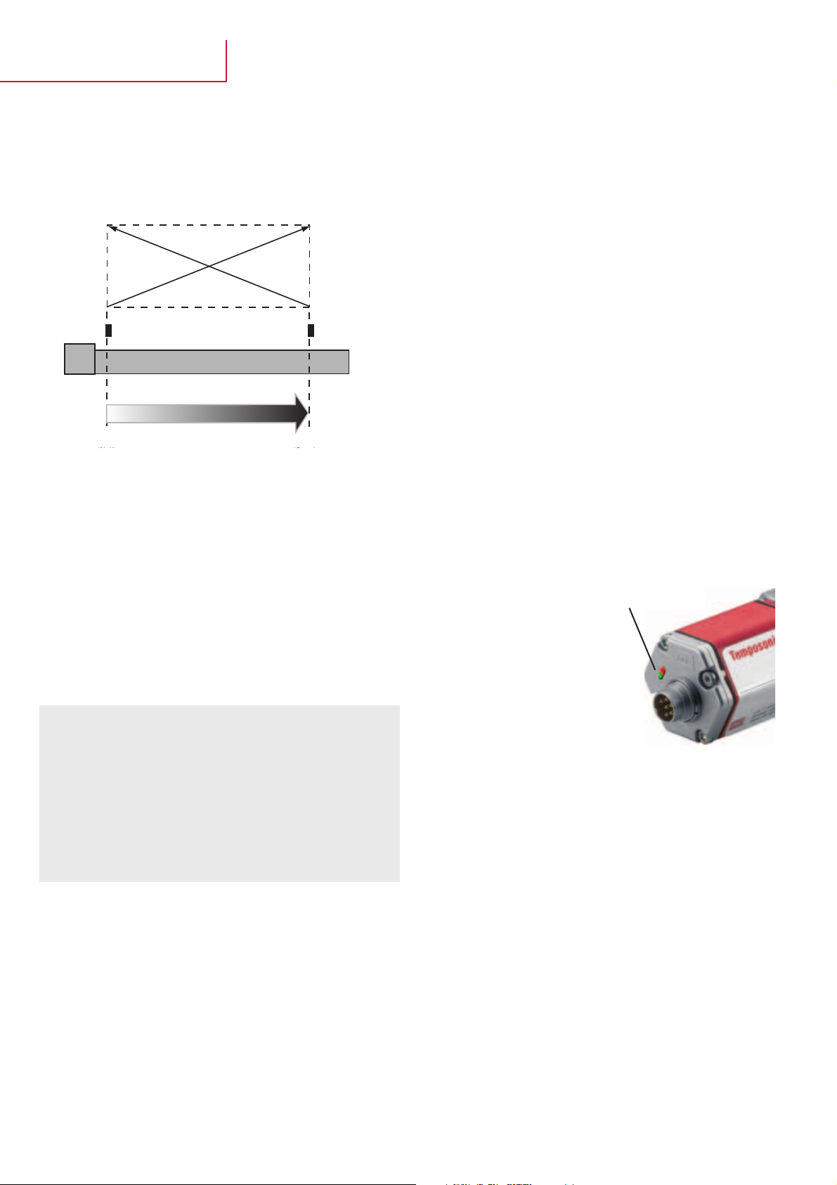
2. Move the position magnet to the appropriate ‘Setpoint 1’ position.
Do not allow the magnet to move until step 4. Use ‘Null’ up or ‘Null’ down
buttons to increase or decrease the output shown on the multimeter, (press
and hold the button for at least a half second).
3. The increments by which the value is adjusted can be changed from coarse
to fine by pressing the programmers’ center button. Coarse mode adjust
yields output changes equivalent to 3 - 5 mm steps. Fine mode adjust yields
output changes equivalent to 0.35 mm steps for ‘Null’ adjustments
and 0.7 mm steps for ‘Span’ adjustments.
4. Move the position magnet to the Setpoint 2 position. Do not allow the
magnet to move until step 5, Use ‘Span’ Up or ‘Span’ Down buttons to
increase or decrease the output shown on the multimeter.
To fine-tune the adjustment, repeat steps 2 and 4. Use the fine mode adjus-
ment feature if necessary. When both ‘Setpoint 1’ and ‘Setpoint 2’ have the
appropriate output values, continue to step 5.
5. After all changes are made, press and hold the programmer’s center button
for 3 seconds. The programmer will confirm that new settings have been
saved by briefly flashing both the Green and Red LEDs. The programmer’s
LEDs will then change to indicate normal sensor functionality (Green ON,
Red OFF).
Meter +
Meter -
0 VDC
24 VDC
red or
brown
white
green
yellow
grey
pink
Cable Function
pink Ausgang -
grau Ausgang +
gelb RS-485 +
grün RS-485 -
weiß Strom 0
rot oder braun Strom 24
Notes
- G-Series Analogue sensor outputs are adjustable over the entire active
stroke length. The minimum adjustment increment is 0.35 mm, and the
minimum spacing between Setpoint 1 and Setpoint 2 is 50 mm.
- Changing the output polarity for switching between forward-acting and
reverse-acting outputs should not be attempted with the Handheld
Programmer. Instead, use the G-Series PC Setup Software to program the
sensor for a different output range. Due to the G-Series method of proce-
sing, (unlike the R-Series Analogue sensor), changing the output polarity
by only adjusting the setpoint values will limit the output range or add
unnecessary cycle time.
- If the sensor had been previously re-programmed to significantly reduce
the distance between setpoints, then it may be necessary to make only
small changes when re-programming the sensor again. Since the output
values are limited in range, it may be necessary to increase the stroke
distance by performing multiple programming cycles. To increase the
distance between the setpoints again, use small changes for the new loca-
tions of Setpoint 1 and/or Setpoint 2. Perform the steps 2 through 5 to
save the new settings. Repeat the whole procedure, as needed, to get
additional distance between setpoints.

I 1I
Temposonics® G-Series
Handheld Programmer
MTS Sensors
© MTS Temposonics®BA G-Series Handheld Programmer 0902010e - Alterations reserved
Deutschland
MTS Sensor Technologie
GmbH & Co. KG
Auf dem Schüffel 9
58513 Lüdenscheid, Germany
Tel.: +49-2351-9587-0
Fax: +49-2351-56491
info@mtssensor.de
www.mtssensor.de
USA
MTS Systems Corporation
Sensors Division
3001 Sheldon Drive
Cary, NC 27513, USA
Tel.: +1-919-677-0100
Fax: +1-919-677-0200
www.mtssensors.com
Japan
MTS Sensors Technology Corp.
737 Aihara-cho,
Machida-shi
Tokyo 194-0211, Japan
Tel.: +81-42-775-3838
Fax: +81-42-775-5512
info@mtssensor.co.jp
www.mtssensor.co.jp
www.mtssensor.com
www.temposonics-shop.de
Other manuals for Temposonics G Series
1
This manual suits for next models
4