Mu-Tron Pedal Flanger 3007 User manual

Feedback
Rate
Start
Stop
Pedal Flanger
3007
Input
Output
Effect Pedal
PEDAL FLANGER (MUTRON)
Build Documents
18vdc
12vac

PEDAL FLANGER (MUTRON)
Contents
Page
Cover Sheet………………………………………..1
Contents…………………………………………….2-3
Introduction………………………………………4
Pedal Flanger Full Schematic………………5
Main Board Schematic…………………………6
LED/LDR Board Schematic………………….7
Main Board Overlay…………………………….8
LED/LDR Board Overlay……………………..9
Main Board PCB………………………………….10
LED/LDR Board PCB…………………………..11
Main Board BOM Quantities…………………12
Main Board BOM Designations………........13-15
LED/LDR Board BOM Quantities………….16
LED/LDR Board BOM Designations………17
Offboard Wiring…………………………………18
Offboard Wiring Connectors……………….19

PEDAL FLANGER (MUTRON)
Contents
Assembly Instructions………………………20-21
Drilling Template Notes / X Wing………22
Drilling Template……………………………..23
LED/LDR Board Fabrication………………24
LED/LDR Board LED Indicator Inst.…..25
Shutter Modification…………………………26
Test Point Fabrication……………………….27
DC Jack Spacer………………………………….28
Rate Indicator Installation………………...29
Calibration Procedures………………………30-32
Test Pint & Trimmer Legend……………….33
Pedal Flanger Artwork………………………34

PEDAL FLANGER (MUTRON)
Introduction
It doesn’t seem that long ago, as a teenager in the seventies, I took in a vast array
of music both past and present. Contained in this music were passages where the
guitar was transformed into something seemingly magical.
As I entered the world of music as a vocalist, I soon discovered what some of these
devices were and how they produced these “magical” sounds.
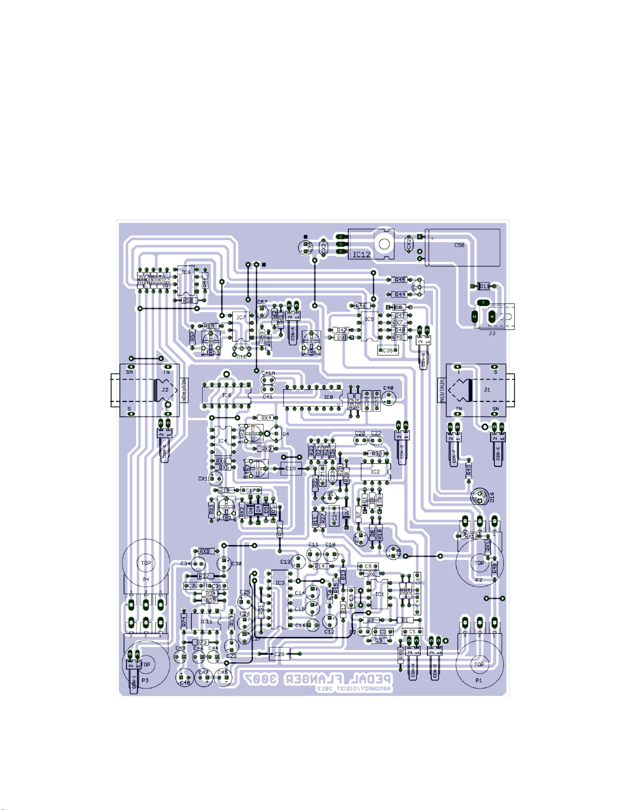
This is one of those devices……….The Mutron Flanger.
The original flanger incorporated the SAD1024 delay IC for its 1024 stage “bucket
brigade” design.
The circuit reproduction offered here follows the same path but with the more
accessible MN3007 1024 stage IC retrofitted in its delay line.
The original design included a transformer mounted in its enclosure.
This reproduction offers a design that can be powered by either an 18VDC center
negative source, or a 12VAC wall transformer. No switching, no component
changes, no circuit board jumpers required!
I would like to thank the many generous people who helped to make this flanger go
from a few bad gut shots and an illegible schematic, to a working device that truly
does produce “magical” sounds!
Greg (Govmnt Lacky), Federico (Fender3D), Ian (Ronan), and the venerable R.G.
(R.G.), Aron for providing such a great meeting place for like minded people -
DIYstompboxes
And last, but certainly not least…..
A very special thank you goes to my partner in crime….Dino (Digi2T)
Who without his dogged persistence, constant nudging, keeping me on track,
answering my countless questions and inquiries, and offering up his flanger for
dissection……..This project never would have got off of the ground.


PEDAL FLANGER (MUTRON)
Main Board Overlay

PEDAL FLANGER (MUTRON)
LED/LDR Board Overlay
Note:
D14 & D15 are installed on trace side
in outer holes on board "outriggers"
See "LED/LDR Board indicator LED
installation" for instructions.

5.32 in
6.50 in
(134.5mm)
(164.7mm)

111.6mm
4.41 in
3.54 in
89.9mm

PEDAL FLANGER (MUTRON)
BOM - Quantities
Ceramic
2 - 10pf
1 - 120pf
1 - 560pf
1 - 680pf
1 - 820pf
2 - .1µf (multilayer ceramic)
Film Box
2 - .001µf
2 - .0015µf
4 - .047µf
3 - .01µf
3 - .22µf
2 - .47µf
Electrolytic
3 - 1µf
3 - 2.2µf
5 - 4.7µf
4 - 10µf
1 - 10µf N.P.
3 - 47µf
1 - 1000µf
Tantalum
1 - 1.5µf *(1)
5 - 4.7µf
Resistors ¼ watt
1 - 100Ω
1 - 150Ω
1 - 180Ω
1 - 750Ω
1 - 1.2K
1 - 1.5K
2 - 2.2K
2 - 2.7K
4 - 4.7K
1 - 5.6K
2 - 6.8K
6 - 10K
5 - 15K
4 - 22K
2 - 27K
1 - 33K
6 - 39K
6 - 47K
2 - 56K
1 - 91K
3 - 100K
1 - 110K
3 - 120K
1 - 200K
1 - 220K
1 - 270K
5 - 390K
2 - 1M
2 - 1.5M
Trim Potentiometers
5 - 10K Piher N6-L50TOC-103
Potentiometers
3- 10KB Alpha RV16AF42
1 - 50KB Alpha RV16AF42
Diodes
6 - 1N914
3 - 1N34A
1 - 1N5819
1 - MSD6102 *(2)
1 - 5mm LED
Transistors
1 - 2N5457
1 - 2SC828R
1 - 2N5088
ICs
6 - RC4558P
1 - NE571
1 - MN3007
1 - CD4046
1 - CD4011
1 - LM7815CT
Misc. Hardware
2 - MONO JACK NMJ4HCD2
1 - DC POWER JACK SPC4077
1 - 3PDT FOOTSWITCH
1 - DPDT FOOTSWITCH
9 - WAFER CONNECTOR RT-ANG 2.54mm
9 - WAFER CONNECTOR HOUSING 2.54mm
* (1) Alternate: 1µf & .47µf in parallel
* (2) Alternate: Two 1N914 diodes matched

PEDAL FLANGER (MUTRON)
BOM - Designations
Part Value
C1- .047µf
C2- 10pf
C3- .047µf
C4- .01µf
C5- .001µf
C6- .047µf
C7- 4.7µf
C8- 2.2µf
C9- .0015µf
C10- 2.2µf
C11- 2.2µf
C12- 10µf
C13- 4.7µf
C14- 4.7µf
C15- 10µf
C16- 4.7µf tant.
C17- .047µf
C19- .47µf
C20- 680pf
C21- .0015µf
C22- 820pf
C23- 560pf
C24- .22µf
C25- 4.7µf
C26- 10µf
C27- 4.7µf tant.
C28- .47µf
C29- 1µf
C30- 1µf
C31- .01µf
C32- .001µf
C34- 10µf N.P.
C35- .22µf
C38- .22µf
C39- .01µf
C40- 4.7µf
C41- 120pf
C41A- 10pf
C44- 4.7µf tant.
C45- 47µf
C46- 4.7µf tant.
C47- 47µf
C48- 47µf
C49- 4.7µf tant.
C50- 1000µf
C57- 1.5µf tant. *(1)
CX1- 1µf
CX2- .1µf multilayer ceramic
CX3- .1µf multilayer ceramic
CX4- 10µf
D1- 1N914
D2- 1N914
D3- 1N914
D4- 1N34A
D5- 1N914
D6- 1N34A
D7- 1N34A
D8- 1N914
D9- 1N914
D10- MSD6102 *(2)
D11- 1N5819
D16- LED 5MM
IC1- RC4558P
IC2- RC4558P
IC3- NE571
IC4- MN3007
IC5- RC4558P
IC6- RC4558P
IC7- RC4558P
IC8- CD4046
IC9- CD4011
IC11- RC4558P
IC12- LM7815CT
Q1- 2N5457
Q2- 2SC828R
Q4- 2N5088
* (1) Alternate: 1µf & .47µf in parallel
* (2) Alternate: Two 1N914 diodes
(matched forward voltage)

PEDAL FLANGER (MUTRON)
BOM - Designations
R1- 4.7K
R2- 390K
R3- 390K
R4- 2.7K
R5- 10K
R6- 6.8K
R7- 180Ω
R8- 390K
R9- 390K
R10- 2.2K
R11- 120K
R12- 27K
R13- 27K
R14- 39K
R15- 47K
R16- 47K
R17- 2.2K
R18- 100K
R22- 22K
R23- 15K
R24- 15K
R25- 15K
R26- 15K
R27- 120K
R28- 200K
R29- 39K
R30- 33K
R31- 6.8K
R32- 10K
R33- 10K
R34- 2.7K
R35- 10K
R40- 47K
R41- 47K
R43- 1.5K
R44- 150Ω
R45- 270K
R46- 47K
R47- 56K
R48- 100Ω
R49- 120K
R50- 4.7K
R51- 22K
R52- 39K
R53- 39K
R54- 39K
R55- 39K
R56- 750Ω
R57- 10K
R58- 1.5M
R59- 47K
R60- 220K
R61- 56K
R62- 390K
R63- 10K
R64- 1.5M
R73- 22K
R74- 22K
RX1- 4.7K
RX2- 4.7K
RX3- 100K
RX4- 100K
RX5- 15K
RX6- 1.2K
RX7- 91K
RX8- 1M
RX9- 1M
RX10- 110K
RX11- 5.6K
TR1- 10K N6-L50TOC-103
TR2- 10K N6-L50TOC-103
TR3- 10K N6-L50TOC-103
TR5- 10K N6-L50TOC-103
TR6- 10K N6-L50TOC-103
P1- 10KB RV16AF42
P2- 50KB RV16AF42
P3- 10KB RV16AF42
P4- 10KB RV16AF42

PEDAL FLANGER (MUTRON)
BOM - Designations
J1- MONO JACK NMJ4HCD2
J2- MONO JACK NMJ4HCD2
J3- DC POWER JACK 2.1MM PCB MOUNT
SW1- 3PDT FOOTSWITCH
SW2- DPDT FOOTSWITCH
CON-A – WAFER CONNECTOR 2.54MM RIGHT ANGLE
CON-B – WAFER CONNECTOR 2.54MM RIGHT ANGLE
CON-C – WAFER CONNECTOR 2.54MM RIGHT ANGLE
CON-D – WAFER CONNECTOR 2.54MM RIGHT ANGLE
CON-E – WAFER CONNECTOR 2.54MM RIGHT ANGLE
CON-F – WAFER CONNECTOR 2.54MM RIGHT ANGLE
CON-G – WAFER CONNECTOR 2.54MM RIGHT ANGLE
CON-H – WAFER CONNECTOR 2.54MM RIGHT ANGLE
CON-I – WAFER CONNECTOR 2.54MM RIGHT ANGLE
CON-A – WAFER CONNECTOR HOUSING 2.54MM
CON-B – WAFER CONNECTOR HOUSING 2.54MM
CON-C – WAFER CONNECTOR HOUSING 2.54MM
CON-D – WAFER CONNECTOR HOUSING 2.54MM
CON-E – WAFER CONNECTOR HOUSING 2.54MM
CON-F – WAFER CONNECTOR HOUSING 2.54MM
CON-G – WAFER CONNECTOR HOUSING 2.54MM
CON-H – WAFER CONNECTOR HOUSING 2.54MM
CON-I – WAFER CONNECTOR HOUSING 2.54MM

PEDAL FLANGER (MUTRON)
LED/LDR BOARD BOM QUANTITIES
Film Box
1 - .0047µf
Resistors ¼ watt
2 - 1.5K
2 - 3.3K
1 - 24K
1 - 56K
1 - 220K
1 - 390K
1 - 1M
Resistors ½ watt
1 - 330Ω
Trim Potentiometers
2 - 10K 3362P
Diodes
2 - 5mm LED (your choice of color)
1 - 3mm LED yellow diffused
Transistors
1 - 2SC828R
ICs
1 - RC4558P
LDRs
2 - Waitrony KE-10720
CONNECTORS
2 - WAFER CONNECTOR RT ANG 2 pin
2.54mm
2 - WAFER CONNECTOR HOUSING 2
pin 2.54mm
1 - WAFER CONNECTOR RT ANG 3 pin
2.54mm
2 - WAFER CONNECTOR HOUSING 3
pin 2.54mm

PEDAL FLANGER (MUTRON)
LED/LDR BOARD BOM DESIGNATIONS
Part Value
C51 .0047µf
D14 LED 5MM (your choice of color)
D15 LED 5MM (your choice of color)
D18 Yellow 3MM diffused
IC10 RC4558P
LDR1 Waitrony KE-10720 LDR
LDR2 Waitrony KE-10720 LDR
Q3 2SC828
R42 1.5K
R49 1.5K
R65 3.3K
R66 3.3K
R67 24K
R68 330R 1/2 watt
R69 220K
R70 1M
R71 56K
R72 390K
T4 10K 1/4" TRIMPOT 3362P
T7 10K 1/4" TRIMPOT 3362P
CON-J - WAFER CONNECTOR RT ANG 3 pin 2.54mm
CON-K - WAFER CONNECTOR RT ANG 2 pin 2.54mm
CON-L - WAFER CONNECTOR RT ANG 2 pin 2.54mm
CON-J - WAFER CONNECTOR HOUSING 3 pin 2.54mm
CON-K - WAFER CONNECTOR HOUSING 2 pin 2.54mm
CON-L - WAFER CONNECTOR HOUSING 2 pin 2.54mm

4
5
6
1
2
3
9
8
74
5
6
1
2
3
SW2 SW1
PEDAL FLANGER (MUTRON)
OFF BOARD WIRING
LEGEND

PEDAL FLANGER (MUTRON)
Offboard Wiring Connectors
Con A-1SW2 lug1
Con A-2N/C
Con B-1SW2 lug6
Con B-2SW1 lug6
Con C-1SW1 lug2
Con C-2shield
Con D-1SW2 lug5
Con D-2SW2 lug2
Con E-1shield
Con E-2SW1 lug8
Con F-1SW2 lug4
Con F-2N/C
Con G-1Con J pin2
Con G-2Con J pin3
Con H-1shield
Con H-2SW1 lug7
Con I-1SW1 lug1
Con I-2shield
Con J-1SW2 lug3
Con J-2Con G pin1
Con J-3Con G pin2
Con K-1N/C
Con K-2SW2 lug6
Con L-1SW1 lug4
Con L-2N/C
SW1 lug5 connects
to SW2 lug5
Note:
Con C, Con E, Con H, and Con I are wired using RG174U shielded cable.

PEDAL FLANGER (MUTRON)
Assembly Instructions
Disassembly of Morley enclosure
It is necessary to remove the pedal assembly from the enclosure
to drill new holes.
Remove the bottom cover. Remove the input and output jack
nuts.
Remove the four hex nuts holding the original volume circuit
board in place. Remove the volume circuit board.
Remove the next four hex nuts that secure the pedal assembly.
Remove the shutter by inserting a small diameter Phillips
screwdriver into the screw access hole on the lower left side of
the pedal.
Modify the shutter (see Pedal shutter modification) and reinstall
on pedal assembly.
Reassembly of foot pedal
With pedal bracket in “toe down” position, insert all four machine
screws and washers in pedal bracket holes.
Secure screws on each side of bracket with tape.
Carefully place pedal over top of enclosure and insert screws into
enclosure holes.
Replace hex nuts, tighten, and remove tape.
Install the populated LED/LDR board and replace the four hex
nuts.
Table of contents