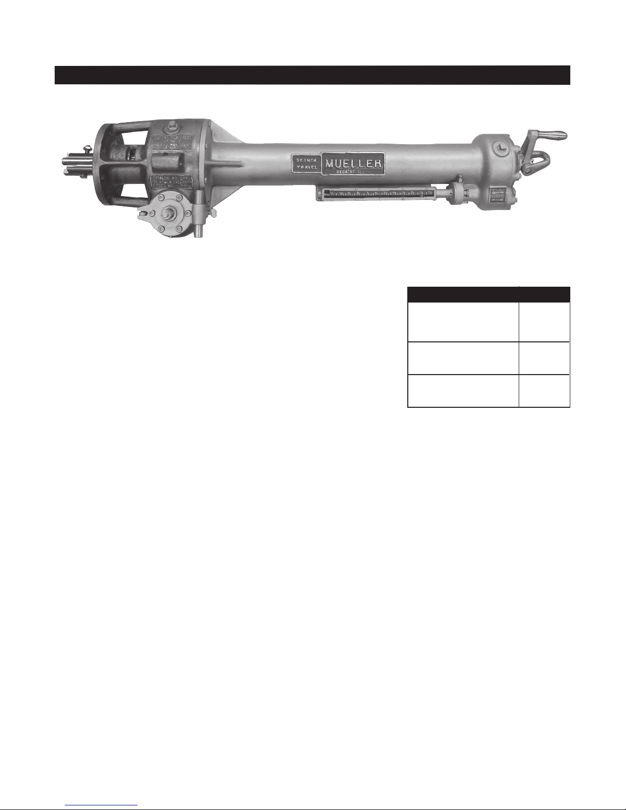
MUELLER® C1-36 Drilling Machines
Operating Instructions
4
b) 2½”– 3”/DN65 – DN80. Assemble
both the pilot drill and the shell
cutter to the cutter arbor Remove
retaining screw from the shank of
the arbor. Insert the shank of the
arbor into the socket in the boring
bar. Align the bolt hole in the end
of the boring bar with the tapped
hole in the shank of the arbor and
replace the retaining screw.
c) Sizes larger than 3”/DN80.
Assemble shell cutter and cutter
hub. Insert the end of the pilot
drill into the socket in the boring
bar. Slide cutter hub and shell
cutter over the end of the boring
bar. Align the holes in the cutter
hub, boring bar and pilot drill
and attach to boring bar with hub
retaining bolt.
Coat cutter and pilot drill thoroughly
with Mueller cutting grease. DO NOT
use cutting grease when cutting AC
or concrete pipe.
6. The term “valve”, as used in these
instructions, refers to whatever
type of valving means that is being
used between the machine and the
main. This might be a tapping valve,
standard gate valve or line stopper
tting. If valve is being used, open
completely and measure, or check,
the exact size of opening and size
of cutter to make sure the entire
opening is clear and unobstructed
and the cutter will pass freely.
7. Retract boring bar to its rearmost
position by rotating feed crank
clockwise.
8. Place the machine (with adapter
and drilling equipment assembled) in
drilling position. For horizontal use,
support the assemble by blocking up
under the machine and valve.
NOTE: Make certain machined
recess on adapter and lip on
adapter ange and machine
ange to be sure they are ush.
1. INSPECT CUTTER AND PILOT
DRILL TO MAKE SURE THAT THEY
ARE SHARP. IF CUTTER IS DULL
IT SHOULD BE SHARPENED AS
DESCRIBED IN MAINTENANCE
INSTRUCTIONS.
2. Bolt proper size adapter to front
of machine, being sure machine-to-
adapter gasket is in good condition
and in place. (All gaskets should be
replaced periodically.)
NOTE: Make certain machined
recess on adapter and lip on
adapter ange and machine
ange are ush.
3. Release automatic feed by
pulling out automatic feed knob or
disengaging with Auto Feed Lever.
(Directions are indicated on panel on
rear of torque tube.)
4. Advance boring bar by rotating
feed crank counter-clockwise until
hub retaining bolt in boring bar is
exposed beyond face of adapter.
(Directions are indicated on panel on
rear cover of torque tube.) Remove
hub retaining bolt.
5. Attach proper drilling equipment
to boring bar. Check detent type
pilot drills before each operation to
make sure the detents will move
completely to the submerged
position.
a) 1½”– 2”/DN40 – DN50. Remove
the retaining screws from the
shank of the drill. Insert the shank
into the socket in the boring
bar. Align the hole in the end of
the boring bar with the tapped
hole in the shank of the drill and
replace the retaining screws. See
instructions under CAUTION on
page 5.
a) Place machine and adapter
against valve, allowing cutter to
extend into the end of the valve.
Cutter must not interfere with
operation of the valve. (When
machine is used horizontally, the
driving spindle should be at a right
angle to the main.) Bolt adapter to
outlet ange of the valve, making
certain that the adapter gasket is
in place.
9.Test set up for pressure tightness.
10. Rotate feed crank counter-
clockwise to advance boring bar
until pilot drill contacts the main. One
turn of the feed crank moves the
boring bar 1/6“ (4mm) – 6 revolutions
equal 1” (25mm). For C1-36-99002
machine, 8 revolutions equal 1”
(25mm). Back up boring bar 1/4 turn
of feed crank clockwise to release
tension between pilot drill and main.
11. Engage automatic feed by
pushing in on automatic feed knob.
12. Rotate feed crank clockwise
until dive key engages. This can be
felt when feed crank ceases to freely
rotate.
13. Set feed indicator to zero. Mark
the point on feed indicator that the
arrow will reach when cut will be
completed. See Pages 7, 8, 9 and
10 for travel chart.
a) When using the C1-36 Machine
and Mueller Air or Hydraulic
Motors
Refer to form 12237 for H-614 Air
motor, Form 12480 for Hydraulic
motor.
If cutting becomes difcult and
stalling occurs follow one of the
methods listed in instruction 20.