Mueller DH-5 Instruction Manual

Customer Service Center
Decatur, Illinois
800.798.3131
www.muellergas.com
moreinfo@muellercompany.com
All warranties, expressed or implied, for Mueller Drilling Machines are
rendered null and void if the machines are used with shell cutters or
equipment manufactured by someone other than Mueller Co.
WARNING:
1. Read and follow instructions carefully. Proper training and periodic
review regarding the use of this equipment is essential to prevent possible
serious injury and/or property damage. The instructions contained
herein were developed for using this equipment on ttings of Mueller
manufacturer only, and may not be applicable for any other use.
2. Do not exceed the pressure ratings of any components or equipment.
Exceeding the rated pressure may result in serious injury and/or property
damage.
3. Safety goggles and other appropriate protective gear should be used.
Failure to do so could result in serious injury.
4. Pressure test, check for and repair leaks in all ttings and components
each time one is installed or any joint or connection is broken. Failure
to nd and repair a leak from any source in the ttings, by-pass lines
or equipment could result in an explosion and subsequent serious injury
and/or property damage.
5. Mueller®Drilling Machines and Equipment have been carefully
designed and engineered to work together as a unit. The use of equipment
manufactured by someone other than Mueller Co. may cause excessive
wear or a malfunction of the Mueller machines.
!
Reliable Connections
TM
DH-5/EH-5
Drilling
Machines
MUELLER®
GAS
opERAtinG inStRUctionS MAnUAL
TABLE OF CONTENTS PAGE
DH-5 Drilling Machine General Information 2
EH-5 Drilling Machine General Information 3
Operating Instructions 4-5
DH-5 Drilling Machine Parts 6
EH-5 Drilling Machine Parts 7

MUELLER® DH-5 /EH-5 Drilling Machines
General Information
2
Feed Tube & Yoke
Collar
Ratchet Handle
Oil Hole
Clean-Out Notch
Bleeder Valve
Capacity and Use
The DH-5 Drilling Machine is a hand
or power operated machine used for
drilling holes 1/8” to 21/8” inclusive,
in any size or kind of pipe (Under
certain conditions the maximum size
may be increased to 33/4”.)
For complete information on the
uses of this machine and the tools
and equipment required for its use
see the latest Mueller Gas Catalog
at muellergas.com.
Working Pressure and
Temperature Rating
Working Pressure
The working pressure or
temperature rating is reduced
accordingly if any attachment, valve,
or temperature during the drilling
operation has a maximum working
pressure or temperature rating
Equipment Furnished
The machine adapter, cutter
arbor, shell cutter and pilot drill
shown at right are not included in
the equipment furnished with this
machine. These items must be
ordered according to the size and
type required.
Length of Travel
DH-5 Drilling Machine has
NOTE: For Operating Instructions
see pages 4 and 5. For DH-5
Drilling Machine Parts see page 6.
Machine Weight Chart
DESCRIPTION DH-5
Machine & equipment
shipped in wooden (48.5 kg)
storage chest
67 lb
Cutting Grease
Double Open-end Wrench
Adjustable Wrench
Body Gasket
DH-5 Drilling MacHine
Machine Adapter Nipple
Cutter Arbor
Shell Cutter
Pilot Drill
Locking Mechanism
Body Gasket

Feed Tube & Yoke
Collar
Ratchet Handle
Oil Hole
Clean-Out Notch
Bleeder Valve
Machine Adapter Nipple
Drill Holder
Drill
Cutting Grease
2 Double Open-end Wrench
Adjustable Wrench
MUELLER® DH-5 /EH-5 Drilling Machines
General Information
3
Capacity and Use
The EH-5 Drilling Machine is a hand
or power operated machine used for
drilling holes 1/8” to 21/8” inclusive,
in any size or kind of pipe (Under
certain conditions the maximum size
may be increased to 33/4”.)
For complete information on the
uses of these machines and the
equipment and attachments required
for their use see the latest Mueller
Gas Catalog at muellergas.com.
Working Pressure and
Temperature Rating
Working Pressure
The working pressure or
temperature rating is reduced
accordingly if any attachment, valve,
or temperature during the drilling
operation has a maximum working
pressure or temperature rating
Equipment Furnished
9/16” x 11/16”
3/4” x 13/16”
The machine adapter, drill holder and
drill shown at right are not included
in the equipment furnished with
this machine. These items must be
ordered according to the size and
type required.
Length of Travel
EH-5 Drilling Machine has
121/8
NOTE: For Operating Instructions
see pages 4 and 5. For EH-5
Drilling Machine Parts see page 7.
Machine Weight Chart
DESCRIPTION EH-5
Machine & equipment 52 lb
shipped in wooden (23.5 kg)
storage chest
24 lb
eH-5 Drilling MacHine
Body Gasket

MUELLER® DH-5 /EH-5 Drilling Machines
Operating Instructions
4
8. Open valve being used.
9.
drill contacts the pipe to be drilled.
10.
amount.
11.
that the yoke is engaged with the
top of the friction collar on boring
mechanism on side of yoke so that it
is positioned under friction collar and
lock in place with operating screw.
Close bleeder located at bottom of
the machine before drilling operation
is begun.
12. Measure and mark the travel
required to complete the drilling
operation. (Mark the point on the
body that the feed tube will reach
when drilling is completed.)
13. DRILL MAIN – POWER
OPERATED METHOD USING
H-604 AIR OR H-704 HYDRAULIC
POWERED OPERATOR.
The DH-5 and EH-5 Drilling
Machines have been designed
to permit the addition of a power
operator. The power operator will
drive the tools and provide automatic
feed during the drilling operation.
IMPORTANT: When using H-604
air motor power operator,
maintain pressure of 90psi. We
recommend the use of a gage
at the throttle to determine the
actual pressure of air at the motor.
1. Oil all working parts, especially
the collar on the boring bar. Keep
oil treated surfaces and boring bar
well lubricated and free from dirt and
foreign material. (Invert the DH-5
or EH-5 Machine and lubricate it
through both lower and top oil holes
in addition to the points mentioned
previously.)
DH-5 and EH-5 Machines are
equipped with O-ring packing.
Under normal conditions the only
maintenance required for these
O-rings is lubrication. If the O-rings
should become excessively worn
they should be replaced.
NOTE: Avoid using petroleum-
based lubricants.
2.
tools may be attached.
3.
bar. If drilling tools to be used
will not pass completely through
the machine adapter to be used,
attach the machine adapter before
attaching the drilling tools (see
instruction no. 5).
4. ®
cutting grease to the leading edges
of the shell cutter and/or drill.
5.
adapter to the body of the machine
making sure that the body gasket
or washer is in place and in good
condition.
6.
position.
7.
machine adapter to the valve that is
to be drilled through.
The gear case attaches to the
machine by the means of two
sockets. The inner or small socket
drives the boring bar. The outer
or large socket drives the feed
yoke through a gear reduction
as the boring bar is rotated. The
revolution of the boring bar.
The operator takes the torque
of the motor resulting from the
drilling operation, so the motors
are equipped with a squeeze-type
trigger throttle. If for any reason a
drill should stick, the motor can be
shut off quickly.
a) Place the gear case and motor on
the drilling machine aligning the
sockets with the square shank
on the boring bar and feed yoke.
should be closed and wing nut
tightened securely.
clockwise rotation of boring bar.
5
operation

MUELLER® DH-5 /EH-5 Drilling Machines
Operating Instructions
5
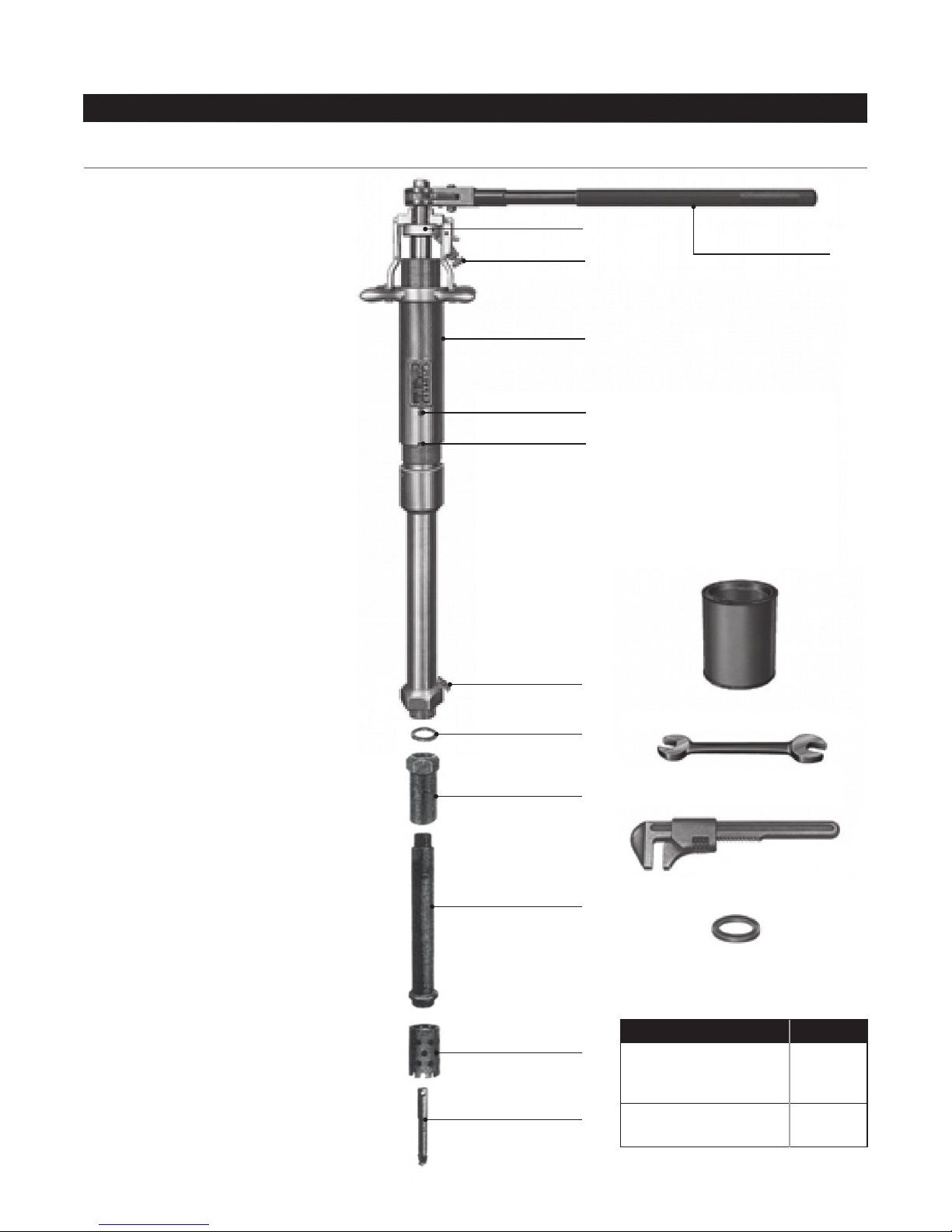
15. When drilling operation is
completed, turn operating screw
on locking mechanism counter-
clockwise to unlock pivot arm.
collar and retract boring bar to its
drill or pilot drill clears the valve gate.
CAUTION: DO NOT reverse
rotation of ratchet handle when
retracting the boring bar.
16. Close valve being used. Open
bleeder valve located at bottom of
machine to bleed gas from machine
before adapter and machine are
removed from valve.
17.
machine adapter as a unit.
18.
machine adapter and drilling tools
from machine.
19.
foreign material from machine and
give drilling tools a light coat of oil
to protect them from rust. When not
in use, the machine and equipment
furnished with each machine should
be stored in the box furnished. The
machines should be disassembled
periodically, and the boring bar and
machine body thoroughly cleaned
any grit, chips, or other foreign
material that might have possibly
accumulated on the boring bar or
in the body of the machine may be
detected and removed before any
foreign material on either the boring
bar or inside the body will restrict the
reverse travel of the boring bar.
13A. DRILL MAIN – HAND
OPERATED METHOD
Drill the hole by operating the ratchet
handle clockwise and turning the
feed tube and yoke clockwise a
little at a time. Use a light, even feed
at the start, then a heavier feed and
to the balanced pressure design of
these machines, the line pressure
thrust load will not be transmitted to
the boring bar. The special locking
mechanism that locks the boring bar
to the feed yoke prevents the drill
from spiraling into the hole before
the hole is completely drilled. To
prevent over-feeding when drilling
small holes and also when starting
to drill larger holes, apply the feed
by gripping the knurled section of
the feed tube instead of the feed
handles. This will apply a light, even
feed. Feed handles should be used
to apply a heavier feed.
NOTE: When nearing the
completion of the cut, DO NOT
over-feed or the cutting tools may
be forced through before all the
metal is drilled or cut out.
The EH-5 Machine is furnished with
a combination ratchet and crank
handle. When drilling small holes,
the crank handle should be turned
upward and rotated in continuous
circles instead of ratcheting.
14. Continue drilling operation until
pipe is drilled through completely.
This can be determined by the
feel of the feeding mechanism, the
pull on the ratchet handle or by
measuring the advance of the boring
bar. If drilling is not completed,
retract boring bar slightly and ratchet
and feed slowly to remove the
remaining metal a little at a time.
SPECIAL NOTE: In general, the
machines should be lubricated
as described in instruction No.
1. However, due to extreme
conditions in some areas (dust,
sand, etc.) it may be advisable
not to lubricate the feed sleeve or
threaded ports of these machines
since it would tend to increase the
abrasive or wearing action. This
procedure, of course, must be at
the discretion of the operator.
!

MUELLER® DH-5 /EH-5 Drilling Machines
DH-5 Drilling Machine Parts
6
parts list
3
39
2
41
1
26
40
38
37
35
36
34
33
32
31
30
14
43
29
28
27
456
7
42
8
9
10
11
12
13
14
15
16
17
18
19
20
21
22
23
24
25
44
*Order both parts when replacing either one.
number and model number of machine)
NOTE: These illustrations are for parts identification only. DO NOT
use these illustrations for assembly or disassembly of machine.
Mueller Co. offers a machine repair service. Contact Mueller Customer
Service Center for details.
ID Partno. Partname
1 86391 HandleExtension
2 85308 RatchetHandle
3 46029 RetainerNut
4 40007 Spring
5 40006 SpringPin
6 40004 RatchetDog
7 40137 RatchetWheel
8 502027 Rollpin
9 502025 PivotArm
10 502026 PivotArmSpring
11 502029 LockNut
12 502028 OperatingScrew
13 503319 BodyBushing
14 79268 BoringBarO-ring(6)
15 500652 O-ring
16 301170 BodySetScrew
17 503318 Body
18 40870 BleederValve
19 33278 BodyGasket(2)
20 580991 BoringBarComplete
21 500653 RetainingScrew
22 500654 RetainerScrew
23 500655 Screen
24 51427 FreezePlug
25 78827 BoringBarO-ring
26 88366 CuttingGrease
27 58196 Wrench
28 91664 AdjustableWrench
29 89276 Cylinder
30 526254 CylinderBushing
31 580992 FrictionCollar
32 503324 Rollpin
33 580994 FeedTube&YokeComplete
34 50133 Washers
35 79745 RetainerScrews
36 500851 Detents
37 59810 DetentSprings
38 305006 DetentRetainerScrews
39 40139 Stud
40 40138* Bolt
41 80111 HandleBar
42 46255* Nut
43 48175 O-ring
44 45374 O-ring(3)
45 680352 StorageChest(notshown)

MUELLER® DH-5 /EH-5 Drilling Machines
EH-5 Drilling Machine Parts
7
parts list
10
2
1
39
13
27
16
30
38
29
28
40
34
35
36
32
5
6
12
25
8
26
3
15
18
19
37
31
4
9
7
11
24
23
22
21
20
17
14
33 NOTE: These illustrations are for parts
identification only. DO NOT use these
illustrations for assembly or disassembly
of machine. Mueller Co. offers a machine
repair service. Contact Mueller Customer
Service Center for details.
number and model number of machine)
ID Partno. Partname
1 580897 RatchetHandleComplete
2 80085 CrankHandle
3 500635 HandlePin
4 51484 Handle
5 83431 KnobComplete
6 500803 OperatingPin
7 37863 DetentKnob
8 51426 RatchetDog
9 37883 Spring
10 502029 LockNut
11 502028 OperatingScrew
12 537126 Bushing(2)
13 312443 StemFastener(2)
14 51427 FreezePlug
15 503162 RatchetWheel
16 503163 WheelBushing
17 51428 RetainingRing
18 503160 BoringBar(Top)
19 305006 HexSocketSetScrew(2)
20 59810 Spring(2)
21 500851 Detent(2)
22 502025 Arm
23 502026 Spring
24 502027 RollPin
25 503158 RollPin
26 48130 FrictionCollarPin
27 580610 FrictionCollar
28 79345 O-ring
29 96993 SetScrew
30 79350 O-ring(2)
31 40870 DrainValve
32 47756 FiberGasket
33 526550 BoringBar(Bottom)
34 91664 AdjustableWrench
35 96536 Wrench3/4”x13/16”
36 59787 Wrench9/16”x11/16”
37 88366 CuttingGrease
38 681570 FeedTubeAndYoke
39 526552 Body
40 526551 Cylinder
41 311658 StorageChest(notshown)

www.muellergas.com
moreinfo@muellercompany.com
Form 9675 – Rev 08/17
Reliable Connections
TM
International
www.mueller-international.com
international@muellercompany.com
This manual suits for next models
1
Table of contents
Other Mueller Drill manuals
Popular Drill manuals by other brands

Metabo HPT
Metabo HPT DS 18DEX Safety instructions and instruction manual

RIDGID
RIDGID R5013 Operator's manual

Parkside Performance
Parkside Performance PKHAP 20-Li A1 Translation of the original instructions

Flex
Flex BRL 721 VE instruction manual

PROFECO
PROFECO 77466 instruction manual

Craftsman
Craftsman 113.213151 owner's manual