Mueller HG-1 Instruction Manual

TABLE OF CONTENTS PAGE
OPERATING INSTRUCTIONS MANUAL
WARNING:
1. Read and follow instructions carefully. Proper training and periodic review
regarding the use of this equipment is essential to prevent possible serious injury
and/or property damage. The instructions contained herein were developed for
using this equipment on ttings manufactured by Mueller Co. only, and may not be
applicable for any other use.
2. DO NOT exceed the pressure ratings of any components or equipment. Exceeding
the rated pressure may result in serious injury and/or property damage.
3. Safety goggles and other appropriate protective gear should be used. Failure to do
so could result in serious injury.
HG-1 Automatic
Flushing System
Installation Instructions 2
Programming Unit 3 - 5
Assembly, Disassembly &
Maintenance Instructions 6
Troubleshooting 7
Options 8
Parts 9
Notes 10
F 12769 4/20
!

2
HG-1 FLUSHING SYSTEM
Installation Instructions
GENERAL
INSTALLATION
Please read and retain this
manual. It will be helpful for
future reference, training,
troubleshooting, and maintenance.
Site Evaluation
Each Hydro-Guard installation is
unique and will require a minimum
of advance planning. Prior to the
installation of the device, the
drainage patterns for the intended
the dosage and contact times
recommended by the AWWA.
7. The Hydro-Guard Automatic
Flushing Device may now be
programmed and placed
into service.
Overview
The Hydro-Guard HG-1 Automatic
Flushing System, the industry’s
premium patented, programmable
flushing apparatus, is suitable for
year-round use in warm climates.
This Automatic Flushing System
has been designed, engineered,
and manufactured to provide
outstanding dependability
and performance.
Hydro-Guard HG-1 Atmospherically
Discharged Flushing Unit
1. Remove the Hydro-Guard Unit
from its packaging and inspect for
possible damage during shipping.
2. Excavate a suitably-sized ditch
ensuring it is connected on one
side to the utility’s service line
trench. Remove any debris that
might create uneven pressure
on the Unit. Compact the bottom
of the hole in order to minimize
settling after installation. Place
#57 stone, then non-compacted
clean bedding material within the
bottom of the hole.
3. Slowly lower the Hydro-Guard
Unit into place, pressing it firmly
into the noncompacted bedding
material until it is fully seated.
4. Connect the utility’s water system
to the Hydro-Guard Unit by means
of the 2" threaded connection.
Ensure that the Unit is level before
beginning the backfilling operation
(The bottom of the ground plate
should be approximately 1" above
the final grade).
5. Backfill the hole around the Unit
with clean fill and/or #57 stone.
Backfilling should be accomplished
in 6" compacted lifts. Check that
the Unit is level.
6. Disinfect the Hydro-Guard
Flushing Device in accordance with
the utility’s policy. Do not exceed
installation location should be
reviewed. The drainage pattern must
permit discharged water to flow
away from the Hydro-Guard Unit in
the case of a backflow situation. In
cold-weather applications, multiple
nightly flushes are effective in
managing discharge volumes and
preventing the accumulation of ice.
TYPICAL INSTALLATION
Erosion
Control Plate
Sample Port Quick
Connect (HG-S116
Sample Valve Optional)
2" Control
Valve
Coupling (by others)
26"
§
UV Protected
Housing
Programmer
Dechlorination
System
Cam Lock
Release System
2" MIP Connection
(provided)
16"
Air Gap
Supply Line (by others)
2" Mueller Curb Stop (sold separately)
Mueller Valve Box
(Sold Separately)

3
HG-1 FLUSHING SYSTEM
Programming Unit
PROGRAMMING HYDRO-GUARD UNIT FOR OPERATION
the home screen and tap
the blue TRANSMIT button
(bottom right corner). The
Application aggregates changes
and transmits them to the
controller when you have finished
programming.
CAUTION: Programs A, B,
and C are independent programs,
including start times, run times,
watering days, and water budget.
1. Install the App: – From the App
Store or Google Play Install
the free K-RainBL App:
2. Install a 9 Volt Battery in the
Controller: – Unscrew the cap,
remove the seal and fasten the
battery to the correct terminals.
Replace the seal and cap and hand-
tighten the cap to ensure it seals.
NOTE: Before you launch the App,
you will need to enable locations
services on your phone/tablet in
order for the App to geolocate
your device during installation. On
Android, location services must
be enabled in order for the App to
connect to the BL-KR device.
3. Launch the application on
your Smartphone or Tablet.
4. Associate the controller with
your phone by tapping the Add a
Controller button.
5. The app will now ask what type
of Bluetooth device you would like
to add:
Discharged water flushed from the
Hydro-Guard Unit should be routed
away from the device into the
surrounding environment. Proper
preparation of the area around the
device is essential. Use of sod or
rock is recommended (See typical
installation illustration on page 2).
Technical Data
• Operating temperature range
of 32º to 120º F
• Operating Pressure: 7 to
200 psi
NOTE: Where sustained pressures
may exceed 120 psi the
installation of a pressure reducing
valve (PRV) is recommended.
Battery Life
• Will vary based on number
of cycles per year, operating
pressure, and temperature.
We recommend checking the
battery every 6 months, but in
many cases, you will get more
life out of them.
HG-1 (REQUIRES CONTROLLER)
The BL-KR battery powered
irrigation module communicates
with the K-Rain BL Application on
a Smartphone or Tablet by using
Bluetooth SMART 4.0, (low energy)
on an iPhone with iOS version 7
minimum or an Android phone/
tablet with Marshmallow version
6.0 or higher.
Impotant
CAUTION: For use only with
9V DC Latching Solenoids. As
some solenoids will come from
the manufacturer with the plunger
already magnetically latched
open, some zones will default
to OPEN. Follow the start-up
procedure for systems with DC
Latching Solenoids. (Page 09)
CAUTION: For every change
to the program in the Mobile
App, you must exit back to
NOTE: The BL-KR V1.0 and BL-KR
V2.0 have identical hardware and
software configurations. The only
distinction is the outside plastic
housing.
6. The App will now search for
devices in range.
7. Choose the Controller. The serial
numbers that populate the device
list can be found on the label
located on the back of the controller
housing with the designation
“Default name.” The App will
indicate that it is in the process of
connecting.
8. Once the device is connected, it
will appear on the home screen when
you launch the Application.
NOTE: You can associate up to 400
devices with the K-Rain BL-KR App.
The number of devices is limited
to the internal memory on the
Smartphone/Tablet.
!
!
!
To add
another
controller, tap
the plus sign
in the upper
right hand
corner of the
home screen.
Application Home Screen:
Device Home Screen:

4
Programming Unit
HG-1 FLUSHING SYSTEM
pressing + or –keys. To change
something not flashing, press
LEFT or RIGHT ARROWS until
desired item is flashing.
Setting Date / Time
1. Press RETURN / ENTER key
until CLOCK icon is displayed.
2. All 4 digits will be displayed
representing the year. Use +or –
keys to change year. Press
RIGHT ARROW key to proceed
to setting month.
3. All 4 digits will be displayed
with two digits on left flashing
representing the MONTH. Use +
or –key to change month. Press
RIGHT ARROW key to proceed to
setting DAY.
4. Only two digits on right will be
flashing, representing the DAY.
Press +or –key to change day.
Press RIGHT ARROW key to
proceed to changing TIME.
5. The AM / PM / 24 time setting
is shown flashing. Press +or –key
to change to AM, PM, or 24-hour
time. Press RIGHT ARROW key to
proceed to setting the HOUR.
6. All 4 numbers are shown with
two numbers on the left flashing,
representing the HOUR. Press +
or –key to change the hour. Press
RIGHT ARROW key to proceed to
setting MINUTES.
7. All 4 numbers are shown with
two numbers on right flashing,
representing MINUTES. Press +or
–key to change minutes. (Pressing
RIGHT ARROW key will return to
YEAR setting at step #2.)
8. Press RETURN / ENTER key
to proceed to next programming
function, or allow controller to
return to idle mode.
Setting Flush Sequence
Start Times
1. Press RETURN / ENTER key
until CLOCK icon is displayed.
2. The START TIME will be
displayed flashing, along with the
program letter (A, B, or C) and
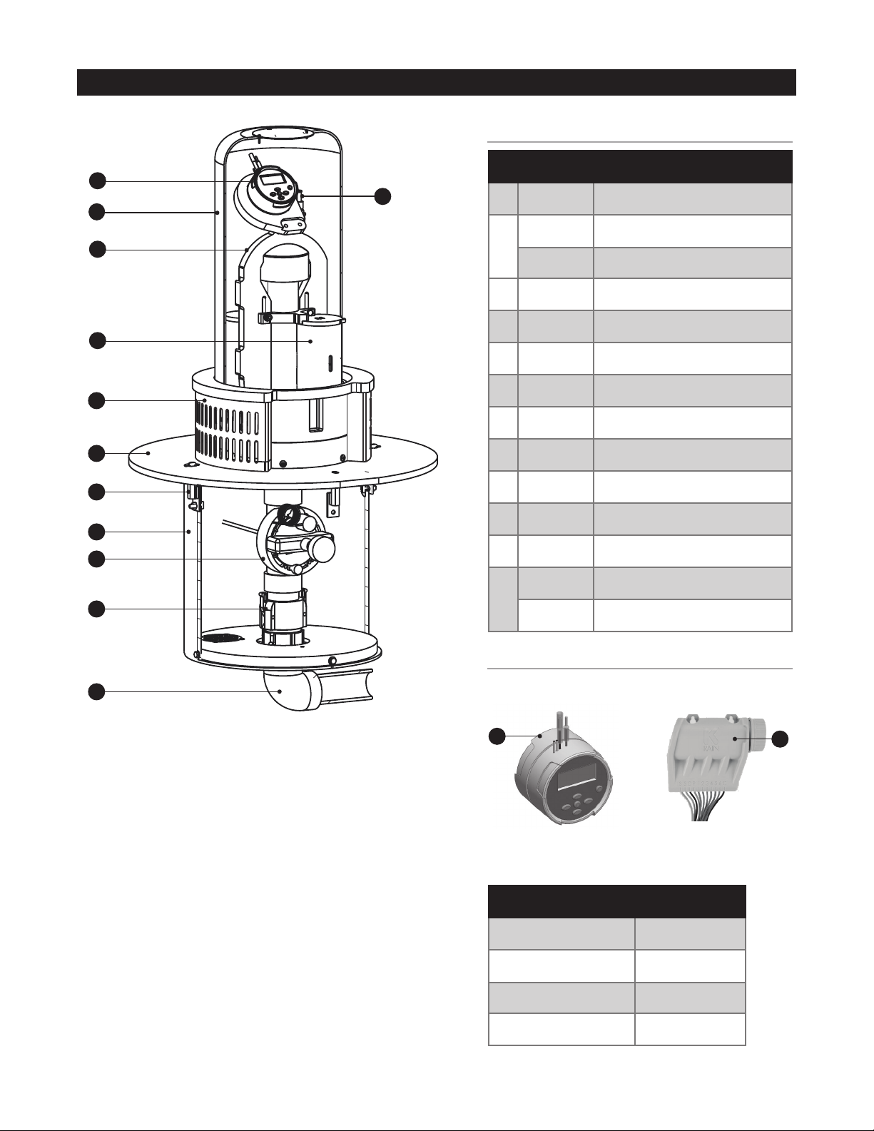
HG-1 BUILT-IN: (INTEGRATED)
NODE Programming Instructions
Batteries
The NODE uses standard 9-volt
alkaline batteries to operate the
control valve and program the
controller. The controller can operate
with one or two batteries installed.
Under normal conditions, potential
life is 1 year for a single battery.
Battery Installation
1. Unscrew rear body of the
NODE to gain access to battery
compartment.
2. Insert battery / batteries into
battery tray and connect the
battery connector to controller.
3. Make sure no water is inside
battery compartment.
4. Screw the NODE rear body back
onto front half.
NOTE: Make sure that seal marker
on rear half of the NODE lines
up with front half, ensuring a
proper seal is created. Also, The
NODE has non-volatile memory,
which allows battery replacement
without losing program
information.
Idle Mode – Waking Up
Normally the NODE display shows
time and day, day of week, and
battery life indicator. During a
short period of inactivity the
display will shut off to retain
battery power Pressing any key will
wake up the NODE to the Idle Mode.
Run Mode
When controller is operating a
program, items shown on display
will include station number (always
“1”), program letter (A, B, or C),
remaining runtime, and a blinking
Rotor icon.
Programming
The NODE has the capability to
hold 3 programs (A, B, C) and 4
start times per program. When
programming, flashing portion
of display can be changed by
start time number (1, 2, 3, or 4) in
the upper left of the display. Up to 4
different start times can be set for
each program.
3. Use +or –key to change START
TIME for program displayed. Each
press of key will change start time
in 15-minute increments.
4. Press RIGHT ARROW key to
add an additional START TIME to
program displayed. The start time
number is shown in upper left
corner of display.
5. Press PRG key to add START
TIME to a different program.
6. Press RETURN / ENTER key
to proceed to next programming
function, or allow controller to return
to idle mode.
Setting Flush Duration Times
1. Press RETURN / ENTER key until
HOURGLASS icon is displayed. RUN
TIME will be displayed flashing.
Also shown is program letter (A, B,
or C) and active station # (always
#1 – all other stations not used) on
lower left side of display.
2. Press +or –key to change
station RUN TIME from 1 minute to
6 hours.
3. Press PRG key to add a RUN
TIME to another program.
4. Press RETURN / ENTER key
to proceed to next programming
function, or allow controller to return
to idle mode.

5
Programming Unit
HG-1 FLUSHING SYSTEM
NOTE:
– Pressing + or – key when running
in MANUAL FLUSH mode will modify
FLUSH TIME for that station.
– Pressing the button when a
station is running in manual
watering will stop flush on the
current station and advance to the
next station.
– Pressing the button when a
station is running in manual
watering will stop the flush on the
current station and revert to the
previous station.
Turn System Off
To turn off controller, press
RETURN / ENTER key button
until icon resembling water spray
and OFF is displayed on screen.
To return controller to auto
programming mode, press RETURN
/ ENTER key. The controller
will immediately return to auto
programming mode and will display
time and battery life indicator.
NODE Quick Check
This circuit diagnostic procedure
can quickly identify “shorts”
commonly caused by faulty
solenoids or when bare common
wire touches a bare station control
wire. To initiate NODE Quick
Check procedure:
1. From Idle Mode, press and hold
+, –, LEFT ARROW, and RIGHT
ARROW keys.
2. Display will show all segments.
Release keys.
3. Press +key to initiate NODE
Quick Check test.
4. Controller will then activate
flushing unit for 1 second to
verify operation.
Setting Flushing Days
1. Press RETURN / ENTER key
until CALENDAR icon is displayed.
The program letter (A, B, or C)
will be displayed. Arrows point
at specific days of week in which
flushing will occur.
2. Press LEFT or RIGHT ARROW
to scroll though days.
3. Press +key to activate that day
for program displayed, or –key to
cancel watering for that day. The
arrow will show on flushing days
for active program.
4. Press PRG key to set days to
flush for a different program,
if desired.
5. Press RETURN / ENTER key
to proceed to next programming
function, or allow controller to
return to idle mode.
Manual Flushing
Manual flushing allows user to test
the Hydro-Guard unit or a program
for a specified run time.
Make sure controller is in Idle Mode.
1. Press and hold RIGHT ARROW
until HAND icon is displayed. The
station number (always #1) will
be displayed in lower left side of
display along with RUN TIME.
2. Use the LEFT or RIGHT ARROW
to select #1 station if not already
displayed, and +or –key to set
manual flushing time.
3. To manually activate a program,
press PRG key. Program letter (A,
B, or C) will show on screen. If a
different program is needed, press
PRG key until desired program
is displayed.
4. To stop MANUAL FLUSHING
cycle press – key until time is
reduced to zero.
5. Press RETURN / ENTER key
to proceed to next programming
function, or allow controller to
return to idle mode.
Battery Life Indicator
Remaining battery life can be
estimated from the battery life
indicator shown on display. The
NODE can operate using either a
single 9-volt battery or using two
9-volt batteries. Using two nine volt
batteries will yield approximately
twice the battery life of a single
9-volt battery. The battery life
indicator chart below shows an
estimate of remaining battery life.
Full: 100 - 60% remaining battery life
Med: 60 - 25% remaining battery life
Low: 25 - 0% remaining battery life
Replace battery immediately!
Resetting Controller
Resetting controller will erase
current program data and restart
controller. A reset does not,
however, delete a program saved to
permanent memory using the Easy
Retrieve Memory feature to save a
preferred program.
1. From Idle Mode, press and hold
–, RIGHT ARROW, and PRG keys.
2. After two seconds screen will go
blank. Continue to hold keys.
3. 12:00 will flash on display.
Release keys.
4. The controller may show a
countdown from 10 to 1 on
display, and then 12:00 am will
be shown flashing when reset is
complete. The controller can now be
reprogrammed.

6
Assembly, Disassembly & Maintenance Instructions
HG-1 FLUSHING SYSTEM
EQUIPMENT & TOOLS NEEDED – PPE: Hard hat, safety shoes, safety vest, safety glasses, work gloves.
Tools: Wrenches, A-311 operating wrench, pliers.
PROGRAMMING HYDRO-GUARD UNIT FOR OPERATION
and lower it onto top of in-ground
section of unit.
4. Line up four holes of Ground
Plate with brackets of in-ground
Protective Sleeve.
CAUTION: do not rotate the
plate more than 90° in either
direction, which could stretch
wiring or poly-tube.
5. Reinstall four Security Screws
and use HG-A104 Security Wrench
to tighten them securely.
6. Lower Dechlorination Chamber
Bracket to original position and
retighten two nuts securely.
7. Check battery life of Battery in
Programming Interface or on-board
Programmer (according to model
of unit), replace and restore
programming if necessary.
8. Align Lock on Exterior Housing
Cover with Locking Bracket on
lower assembly of unit and reinstall
Exterior Housing Cover (lock will
engage when cover is properly
seated).
9. Restore water supply to unit.
Loading Dechlorination Chamber
1. Follow instructions “HG-1
Machine Disassembly”, steps 1
– 3.
2. Slide Bracket upward as
far as possible and remove
Dechlorination Chamber Covers.
3. Check for partially dissolved
chlorine tablets or residuals and
clean the chamber as needed.
4. Insert up to four 3" chlorine
tables in each chamber.
5. Reinstall chamber covers,
lower bracket to secure them and
retighten two nuts securely.
6. Follow instruction #8 above to
reinstall Exterior Housing Cover,
and restore water supply to unit.
The HG-1 Unit is designed to
operate unattended and with
minimal need for service. In the
event it is necessary to service
the flushing unit’s control valve,
solenoid, or any other below-
grade component, or to load the
Dechlorination Chamber please
follow these instructions.
Disassembly
1. Shut off water supply to unit.
2. Use HG-A2023 Security Tool
to unlock and remove protective
Exterior Housing Cover.
3. Loosen, do not remove, two
stainless steel nuts in Bracket
holding Dechlorination Chamber
Covers in place.
4. Use HG-A104 Security Wrench
to remove four security bolts from
Erosion Controlling Ground Plate.
5. Lift upper assembly up and
off pipe leading down into lower
in-ground part of unit, taking care
not to stretch wiring and poly-tube
sampling line.
6. Remove the internal
subassembly from the bottom
plate assembly of the HG-1 by
releasing the Cam-Lock handles at
the base of the female side of the
Cam-Lock.
Reassembly
1. Return internal assembly to
proper location and lock the Cam-
Lock handles in place on the
female side of the Cam-Lock.
2. Pull up on internal assembly
to be sure it is locked in place
(recommendation: use a zip-tie
to hold two Cam-Lock handles
in position to assure they remain
locked in place during operation of
the unit).
3. Gently lift upper section, making
certain to not stretch wires or
poly-tube, and place it over pipe
!

7
Troubleshooting
HG-1 FLUSHING SYSTEM
TROUBLESHOOTING THE PROGRAMMER
TROUBLESHOOTING THE UNIT
plunger is kicking out and
pulling back in by listening
for a click.
• Check to make sure the
flow control knob is open
on the valve OR Check the
pipes for obstructions OR
Check the valve.
The Hydro-Guard Unit will not
shut off:
Possible Causes
• The solenoid is stuck in the
open position or debris is
interfering with the plunger.
• Batteries weak or dead.
• Connection loss from
battery box to solenoid.
• The solenoid is loose or
there is debris in the adapter.
If your Hydro-Guard Unit does
not activate:
Possible Causes
• Water pressure off or low.
• Batteries weak or dead.
• Connection loss from
controller to solenoid.
• Solenoid not working properly.
• Obstruction in flow of water.
Try this Correction
• Check if curb stop is open.
• Change batteries.
• Check connections for
corrosion, breaks, or lack
of connection.
• Run a manual flush and
confirm the solenoid
• There is a hole in or debris
around the diaphragm.
Try this Correction
• Run a manual flush for 1
minute.
• Change batteries.
• Check connections for
corrosion, breaks, or lack
of connection.
• Check the adapters and
solenoid for debris – Run the
electrical systems check.
• Refer to valve
troubleshooting for possible
corrective measures.
PROBLEM CAUSE SOLUTION
Controller does not flush
as desired
Water at main water supply is
shut off
Battery dead Replace battery
Controller improperly programmed Check program and clock settings
Controller set to OFF Set controller to desired program
Blank display
Water does not turn off Overlapping programming Review all programming and edit
any program that is in conflict with
desired off schedule
Clear all programming in memory
and reset
Programmer not communicating Check Programming
Run Manual On / Off with solenoid
removed from valve (hold finger
or object over solenoid plunger to
prevent plunger from dislodging
from solenoid body)
Check wiring for damage and
connectors to ensure proper
connection (red to red & black
to black)
Check main supply valve

8
Options
HG-1 FLUSHING SYSTEM
PROGRAMMING HYDRO-GUARD UNIT FOR OPERATION
The following is a brief
overview and introduction to
Hydro-Guard Options.
Low Lead Brass Internal
Components and Piping
Freeze Protection
The Hydro-Guard HG-1 Unit
is freeze protected to 18" by
virtue of the bury depth of
the main 2" valve. The HG-1
offers a valve bury depth
of approximately 16" with
above ground electronics that
can be powered by a 9-volt
Lithium battery (operational in
temperatures as low as -20° F).
For additional freeze protection,
consider the HG-3 design.
The HG-3 (18" to 108" bury)
is equipped with Mueller's
patented freeze protection
system. The freeze protection
system allows the water in the
service piping to drain from the
device when a flush sequence
has ceased.

9
Parts
HG-1 FLUSHING SYSTEM
REPLACEMENT PARTS
CONTROLLER OPTIONS
ID PART # DESCRIPTION
1 546284 UV Protective Housing
2
HG-123014 Quick Connect / B-QC
HG-123105 Quick Connect Sanitary Cap
3 546703 Riser Assembly
4 546519 OEM Dechlorination System
5 546514 Housing Diffuser Top
6 546292 Ground Plate
7 HG-01141A Stainless Steel Housing Bracket
8 546025 15" PVC Housing Pipe
9 HG-123100 2" Valve 520-050 w/ Flow Control
10 HG-13101 Cam Lock Release System
11 546330 Splash Pad
12
or
13
HG-5292 NODE Controller Sub Assembly
HGI-BL Bluetooth Controller Sub Assembly
PART # PIPE MATERIAL
HG1ARM2BRN018LPLG PVC
HG1AIN2BRN018LPLG Brass
HG1ARM2PVC018LPLG PVC
HG1AIN2PVC018LPLG Brass
10
7
5
1
12
2
3
4
6
8
9
11
12 13
Built-In Controller
(shown above on
illustration) Bluetooth Controller
– OR –

10
Notes
HG-1 FLUSHING SYSTEM

MUELLER®| ECHOLOGICS®| HYDRO GATE®| HYDRO-GUARD®| HYMAX®| JONES®| KRAUSZ®| MI.NET®| MILLIKEN®| PRATT®| SINGER®| U.S. PIPE VALVE AND HYDRANT
INTERNATIONAL – 1.423.490.9555 – www.mueller-international.com – international@muellercompany.com
Mueller refers to one or more of Mueller Water Products, Inc. a Delaware corporation (“MWP”), and its subsidiaries. MWP and each of its
subsidiaries are legally separate and independent entities when providing products and services. MWP does not provide products or services to
third parties. MWP and each of its subsidiaries are liable only for their own acts and omissions and not those of each other. MWP brands include
Mueller®, Echologics®, Hydro Gate®, Hydro-Guard®, HYMAX®, Jones®, Krausz®, Mi.Net®, Milliken®, Pratt®, Pratt Industrial®, Singer®, and
U.S. Pipe Valve & Hydrant. Please see muellerwp.com/brands and krauszusa.com to learn more.
© 2020 Mueller Water Products, Inc. All Rights Reserved. The trademarks, logos and service marks displayed in this document are the property of Mueller Water Products, Inc., its afliates or
other third parties. Products marked with a section symbol (§) are subject to patents or patent applications. For details, visit www.mwppat.com. These products are intended for use in potable
water applications. Please contact your Mueller Sales or Customer Service Representative concerning any other application(s).
Other manuals for HG-1
1
Table of contents
Popular Plumbing Product manuals by other brands

KWC
KWC SIRIUS WB440COP Installation and operating instructions

Tres
Tres 21831202 manual

Glacier bay
Glacier bay 67112W-8004 Installation and care guide

METHVEN
METHVEN Kaha 01-7003 installation guide

Glacier bay
Glacier bay HD59650-0001 Use and care guide

Hans Grohe
Hans Grohe Focus 31132000 Instructions for use/assembly instructions