Muller METS-WTEx User manual

METS-WTEx
METS-WTEx-M
METS-WTEx
Operating Manual
Screw-in Resistance Temperature Sensor
Screw-in Resistance Temperature Sensor Page-1

METS-WTEx-M
Screw-in Resistance Temperature Sensor Page-2
1 General (Information, Signs and Abbreviations) 3
2 Transport, Packaging, Storage 3
3 Safety Instructions 4
4 Ex Safety Instructions 5
4.1 For Your Safety 5
4.2 ATEX Approvals 5
4.3 Special Provisions for Operation in Hazardous Areas 6
4.4 Electrical Characteristics 7
4.5 Environmental Conditions 8
5 Start-Up, Operation 9
5.1 Function 9
5.2 Before Mounting 9
5.3 Product Label 9
5.4 Mounting 9
5.5 Electrical Connection 10
5.6 Pin Assignment 10
5.7 Configuration 11
5.8 Function Test 12
5.9 Fault Detection / Fault Current 12
6 Fault Recovery 13
7 Maintenance, Dismounting, Return, Cleaning, Disposal 14
8 Technical Data 15
9 Dimensions 16
Content

METS-WTEx-M
!
i
!
1.1 For Information
- This operating manual gives important handling instructions for the resistance thermometer. Compliance with all
safety and handling instructions in this manual is a requirement for safe work.
- Qualified personnel must have read and understood this operating manual before mounting and start-up of the
sensor.
- This operating manual is part of the product. Please keep this manual at a place accessible for all users and on-site.
- Please comply with the local regulations and safety instructions for the field of application of this sensor.
- If the serial number on the product label becomes illegible (e.g. through mechanical damage), traceability can not be
ensured.
- The resistance thermometer METS-WTEx described in this manual is carefully designed and manufactured using
state-of-the-art technology. Every component undergoes strict quality inspection in all stages of manufacture.
- The manufacturer's liability is void in the case of any damage caused by using the product contrary to its intended
use, noncompliance with this operating manual, unauthorised modifications to the METS-WTEx or assignment of
insufficiently qualified skilled personnel.
U+: Positive supply connection
U-: Negative supply connection
1 General
2 Transport, Packaging, Storage
Screw-in Resistance Temperature Sensor Page-3
1.2 Signs, Abbreviations
Warning!
Non-compliance can cause injuries to persons and/or the demolition of the device.
There can be a danger to life.
Attention!
Non-compliance can cause faulty device operation or lead to property damage.
Information!
Non-compliance can influence the operation of the device or cause unintentional reactions.
Danger!
Failure to comply with the safety instructions risks serious or fatal injury caused by electrical power.
Warning!
Possible dangerous situations caused by hot surfaces or liquids, which can lead to burns. Please
avoid hot surfaces and liquids.
Warning
Danger
Warning
Check the device for any damage that may have been caused during transportation. Report obvious damage at once.
Do not remove packaging until just before mounting. Keep the packaging, as it will provide optimum protection during
transport (e.g. change in installation site, returns).
For long-term storage, please avoid the following influences:
- Direct sunlight or proximity to hot objects
- Mechanical vibration, mechanical shock (rough mounting)
- Soot, steam, dust and corrosive gases
If possible, store the device inside its original packaging or equivalent
2.1 Transport
2.2 Packaging
2.3 Storage

METS-WTEx-M
!
!
i
!
!
!
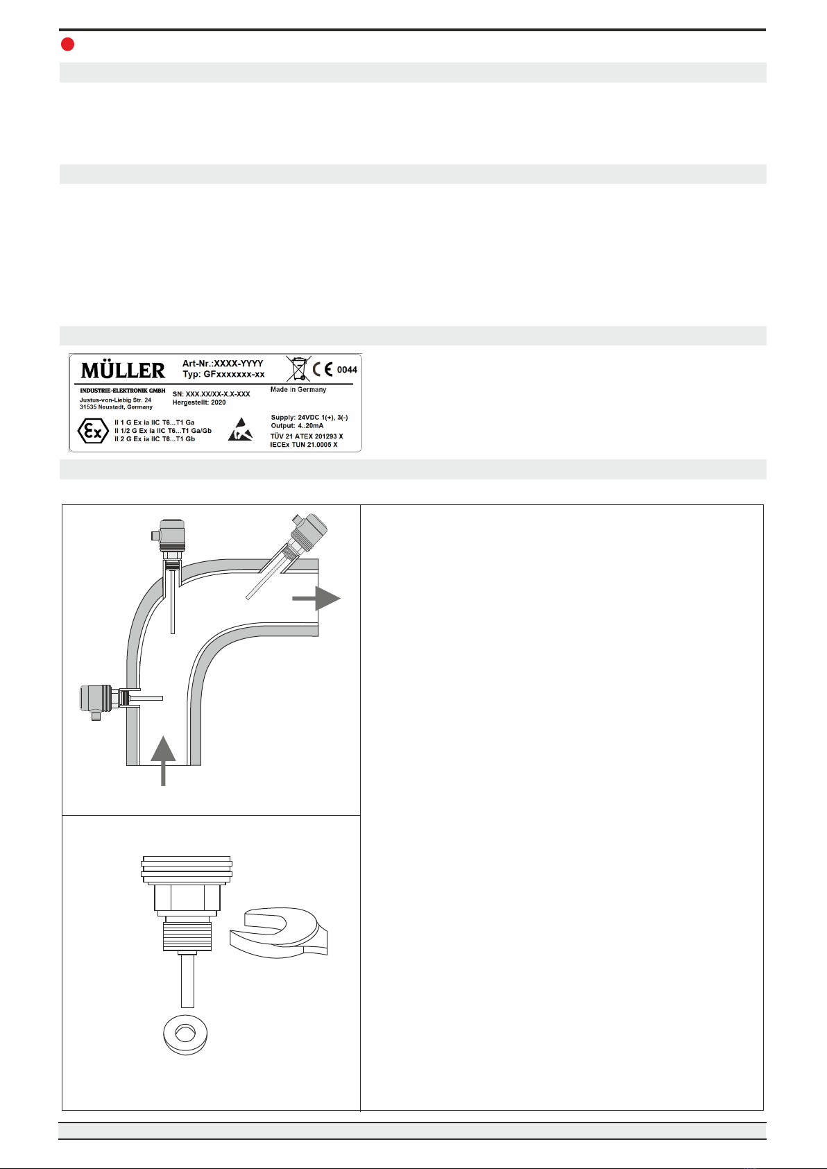
Screw-in Resistance Temperature Sensor Page-4
3 Safety Instructions
Select the correct resistance thermometer based on measurement range, design, suitable material in
contact with medium (corrosion) and specific measurement conditions before mounting, start-up and
operation.
Further important safety instructions are in the individual chapters.
Warning
Warning
3.2 Personnel Qualification
3.3 Special Hazards
For mounting and start-up of the temperature sensor, the personnel will have to be familiar with the applicable
country-specific regulations and directives and have the required qualifications. They must have knowledge of
measurement and control technology, be familiar with electrical circuits, be able to carry out the work described
and recognize potential hazards independently. Depending on the operating conditions, other knowledge may
also be required, e.g. of corrosive media.
Risk of injury if qualification is insufficient
Improper handling can lead to considerable property damage and injury.
- The required tasks as described in this operating manual should only be conducted by qualified
personnel with the qualifications described below.
- Keep unqualified personnel away from hazardous areas.
3.1 Intended Use
The resistance thermometer METS-WTEx is suitable for temperature measurement in liquid and gaseous media. It
has a maximal range of -50…+425°C and can be used under a pressure of up to 25 bar.
The sensor is designed solely for the use and intended purpose as described in this operating manual.
The technical specifications as described in this operating manual are mandatory. Inappropriate handling or operating
the device outside of its technical specifications requires an immediate shutdown and inspection by the manufacturer.
When the device is transported from a cold into a warm environment, condensation can cause a device malfunction.
Wait for device temperature and room temperature to equalize before a new start-up attempt.
The manufacturer shall not be liable for claims of any kind based on operation contrary to the intended use.
Select the appropriate temperature sensor with regard to version and application requirements before
mounting or start-up. Comply with the relevant national regulations (e. g. standards) and comply with
the applicable standards and directives for special applications (e. g. with dangerous media such as
acetylene, flammable gases or liquids and toxic gases or liquids, or with refrigerating systems and
compressors). Non-compliance with the relevant regulations can cause serious injuries and
property damage!
Electrostatic discharge (ESD) protection is required.
The proper use of grounded worktops and personal wristbands is required when working with open
circuits (PCBs) to prevent damage to sensitive electronic components caused by electrostatic
discharge.
Rest media in dismounted devices can represent a danger to people, the environment and the facility.
Please take sufficient security measures!
Do not use this device in safety or emergency stop installations. Improper use of the device may result in
injury.
In case of fault, corrosive media with extreme temperatures and under high pressure or vacuum can be in
contact with the device.
Danger to life due to electric current. If live parts are touched, there is an immediate danger of death.
Installation and mounting of electrical equipment may only be carried out by qualified electricians.
Operation with a defective power supply unit (e.g. short-circuit from mains voltage to output voltage)
can cause life-threatening voltages on the unit.
Warning
Warning
Warning
Danger

METS-WTEx-M
II 1 G Ex ia IIC T6..T1 Ga
II 1/2 G Ex ia IIC T6..T1 Ga/Gb
II 2 G Ex ia IIC T6..T1 Gb
Screw-in Resistance Temperature Sensor Page-5
4 Ex Safety Instructions
Danger
4.1 For Your Safety
Installation and start-up may only be carried out by qualified personnel with knowledge of ignition protection types
as well as provisions and regulations for explosion protection. The country-specific regulations for installation and
operation in hazardous areas must be complied with. The classification of the device must be suitable for the
application. (see "ATEX Approvals" and product label marking)
Danger!
Danger to life due to loss of explosion protection.
Failure to complay with these contents and instructions can lead to a loss of explosion protection.
ATEX
European guideline for explosion protection (Atmosphere=AT, Explosion=EX). The product complies
with the requirements of the European directive 2014/34/EU (ATEX) on explosion protection.
4.2 ATEX Approvals
Approval properties: For gases; Installation in zone 0, zone 1 and zone 2.
ATEX: IECEx TUN 21.0005X
IECEx: TÜV 21 ATEX 201293 X
The complete certificates are available on request and for download from our website www.mueller-ie.com.

METS-WTEx-M
Screw-in Resistance Temperature Sensor Page-6
4 Ex Safety Instructions (Continued)
4.3 Special Provisions for Operation in Hazardous Areas
● The single wires and the free cable ends have to be comply with the requirements of clause 9 of
IEC 60079-14.
● For EPL Ga/Gb applications, reverse heat flow from the process exceeding the permissible ambient
temperature is not allowed and shall be avoided by suitable thermal insulation or suitable neck length of the
tubing.
● For EPL Ga/Gb applications and at risks by pendulum or vibration the respective parts have to be secured
effectively against these dangers.
● For EPL Ga/Gb applications any ignition hazards caused by impact or friction have to be excluded.
● The ambient temperature range depending on temperature class is to be taken from the operating manual.
● The materials in contact with the medium have to be resistant to the medium.
● For EPL Ga/Gb applications the whole device shall be mounted in a way that allows an installation that results
in a sufficient tight joint (IP66 or IP67) or a flameproof joint (IEC 60079-1) in the direction of the less
endangered area.
● The installation in the partition wall between areas with EPL Ga/Gb requirements has to be carried out in such
a way that all metal parts are conductively connected to the metallic container wall, or in the case of containers
made of plastic, all insulated metal parts have to be included in the potential equalization.
● For EPL Ga, EPL Ga/Gb and EPL Gb applications, the temperature sensor METS-WTEx has to be installed
and used in such a way that electrostatic charges due to operation, maintenance and cleaning are excluded.
Device
Ex-Zone
Supply
Non-Ex Zone
e.g. PLC
Controller,
Recorder

METS-WTEx-M
Screw-in Resistance Temperature Sensor Page-7
4 Ex Safety Instructions (Continued)
Parameter
Current Output (2-Wire)
Voltage Output (3-Wire)
Connections
± (I )
out
±
Voltage Ui
30 VDC
30 VDC
Current Ii
110 mA
110 mA
Power Pi
1 W
1 W
Effective internal capacitance Ci
Capacitance of 330m cable = 66 nF
Effective internal inductance Li
Inductance of 330m cable = 330 µH
Connections
...
Uout
Voltage U0
...
= 12,6 V
Current U0
...
= 48 mA
Power P0
...
= 148 mW
Characteristic line
...
linear
Effective internal capacitance Ci
...
Negligibly small
Effective internal inductance Li
...
Negligibly small
4.4 Electrical Characteristics

METS-WTEx-M
Screw-in Resistance Temperature Sensor Page-8
4 Ex Safety Instructions (Continued)
Current Output (2-Wire)
Temperature Class
Environmental Temperature
Medium Temperature
T1
-20 °C ... +75 °C
-50 °C ... +425 °C
T2
-20 °C ... +75 °C
-50 °C ... +275 °C
T3
-20 °C ... +75 °C
-50 °C ... +180 °C
T4
-20 °C ... +75 °C
-50 °C ... +115 °C
T5
-20 °C … +(95 °C - P x 45 K/W),
i
max. 75 °C
-50 °C ... +80 °C
T6
-20 °C … +(80 °C - Pi x 45 K/W),
max. 75 °C
-50 °C ... +65 °C
Voltage Output (3-Wire)
Temperature Class
Environmental Temperature
Medium Temperature
T1
-20 °C ... +50 °C
-50 °C ... +425 °C
T2
-20 °C ... +50 °C
-50 °C ... +275 °C
T3
-20 °C ... +50 °C
-50 °C ... +180 °C
T4
-20 °C ... +50 °C
-50 °C ... +115 °C
T5
-20 °C … +(95 °C - Pi x 55 K/W),
max. 50 °C
-50 °C ... +80 °C
T6
-20 °C … +(80 °C - Pi x 55 K/W),
max. 50 °C
-50 °C ... +65 °C
4.5 Environmental Conditions

METS-WTEx-M
i
A
B
C
Screw-in Resistance Temperature Sensor Page-9
5 Start-Up, Operation
5.4 Mounting Process Connection
Tools: Open-end wrench SW27, screw driver
You will have to provide a sealing element which corresponds
to the application.
Exceptions may be instruments with self-sealing threads (e.g. a
NPT-thread).
When mounting the instrument, ensure that the sealing faces of
the instrument and the measuring p o i n t a r e c l e a n a n d
undamaged.
Screw in or unscrew the instrument only via the flats using a
suitable tool and the prescribed torque. The appropriate torque
depends on the dimension of the process connection and on
the sealing element used (form/material). Do not use the case
as working surface for screwing in or unscrewing the
instrument.
When screwing the transmitter in, ensure that the threads are
not jammed.
If necessary, comply with instructions concerning threaded
holes and welding sockets.
Seal
5.3 Product Label (Example)
The METS-WTEx is screwed directly into the process via the process connection. A change in resistance of the
sensor element in the tip of the thermowell is transformed into an electrical standard signal by a measuring
amplifier. The signal changes proportional to the temperature and can be evaluated.
5.1 Function
5.2 Before Mounting
- Check if a fully assembled temperature sensor has been supplied.
- Inspect the measurement amplifier for possible transport damage. If transport damage is
detected, inform the transport company and supplier immediately.
- Keep the packaging, as it offers optimal protection during transportation.
- Ensure the process connection thread and the connection contacts are protected from damage.
The resistance thermometers are designed for being screw
fitted directly into the process. The insertion length, along
with the flow velocity and viscosity of the process media,
may reduce the maximum viable load of the thermowell.
Installation on pipes
A: on elbows
B: in small pipes, inclined
C: perpendicular to flow direction
Type : Produktkennung Art.No.: Article number
SN : Serial number Man.: Year of manufacture

METS-WTEx-M
123CB
A
!
1
2
3
4
1
3
2
44
11
33
5
5
6
7
22
AB
C
D
E
F
1
3
2
4
1 4
2 3
Screw-in Resistance Temperature Sensor Page-10
5 Start-Up, Operation (Continued)
5.6 Pin Assignment
Connect the instrument to earth via the process connection.
The protection class specified only applies while the pressure transmitter is connected with the female
connectors that provide the corresponding ingress protection.
Ensure that the cable diameter you select fits to the cable gland of the connector. Ensure that the cable
gland of the mounted connector is positioned correctly and that the sealings are available and
undamaged. Tighten the threaded connection and check the correct position of the sealings to ensure
device protection.
Ensure no moisture can seep in at the cable outlets.
Route the cable without applying a force or turning moment to the device.
5.5 Electrical Connection
View: Plug pins of plugs (at device)
LIYCY
4 or 6x0,25 mm²
gray
M12, 4-pole
M12, 5-pole
M12, 8-pole
Super Seal, 3-pole
Deutsch DT04, 3-pole
Deutsch DT04, 4-pole
Bayonet DIN, 4-pole
Valve, 4-pole
MIL, 6-pole
Cable, 4-, 6-pole
+ OUT - + OUT - + OUT -
M12, 4-pole 1 X 3 1 2 3 1 2 3
M12, 5-pole 1 X 3 1 2 3 1 2 3
M12, 8-pole 1 X 3 1 3 8 1 3 8
Super Seal, 3-pole 1 X 3 n/a 1 2 3
Deutsch DT04, 3-pole A X B n/a A C B
Deutsch DT04, 4-pole 1 X 3 1 2 3 1 2 3
Bayonet, 4-pole 1 X 3 1 2 3 1 2 3
Valve, 4-pole 1 X 2 1 3 2 1 3 2
MIL, 6-pole A X C A E C A E C
Cable, n-pole ye X wh ye gn wh ye gn wh
3-Wire DC3-Wire AC
Pin Assignment
2-Wire
Note: X = NC (not connected/unused)
Connection Type

METS-WTEx-M
METS-WTEx
+
_
1
3
+_
+
_
2
OUT (IN)
(V )
CC
(V )
CC
METS-WTEx
+
_
1
3
+_
+
_
Screw-in Resistance Temperature Sensor Page-11
5 Start-Up, Operation (Continued)
5.6.1 Connection Example 2-Wire
Supply
Current / Voltage
Evaluation
e.g. SPS
5.6.2 Connection Example 3-Wire
Supply
Evaluation
e.g. SPS
Current / Voltage
5.7 Configuration
The METS-WTEx can be programmed with the help of the configuration and calibration software TrComm. A DEV-
KMA configurator is required for programming. The TrComm-software is included in the scope of delivery of the
DEV-KMA, alternatively the software is also available separately on request.
For further information, see data sheet DEV-KMA on www.mueller-ie.com.

METS-WTEx-M
i
!
21,0
4,0
20,0
3,6
20,5
3,8
0-1,25 100 103,125
mA
Screw-in Resistance Temperature Sensor Page-12
5 Start-Up, Operation (Continued)
5.8 Function Test
The output signal must be proportional to the temperature. If this is not the case, this can be a sign for a
sensor defect. Please read under Fault Recovery (Page 13) for further information.
- Please open the process connections only when unpressurized.
- Attention: Please comply with the operating parameters as per the technical data (Page 15).
- Attention: Surfaces of device components can become hot during device operation. Please take
care when attempting to touch the temperature sensor.
Warning
5.9 Fault Detection / Fault Current
The device detects sensor break, sensor short circuit (sensor element <> measurement amplifier) and temperatures
outside of the measurement range and shows them as a fault current in the loop circuit.
The current output is proportional to the temperature in a range of 3,8 up to 20,5 mA. If the measured temperature
would equal a current value of below 3,8mA, the device will put out a fault current of 3,6 mA. The same will happen in
case of sensor short circuit. If the current rises above 20,5 mA, a fault current of 21 will be put out. The same is the
case for sensor break.
Measuring signal
(% of range)
Current output and measuring signal

METS-WTEx-M
!
Failure Potential Cause Procedure
No output signal Cable break Check passage
Mechanical load too high or Replace the sensor with a suitable
overtemperature design
No/false output signal Incorrectly wired Comply with pin assignment (see
product label / manual)
Erroneous measured values Sensor drift caused by Replace the sensor with a
overtemperature suitable design
Sensor drift caused by chemical Replace the sensor with a
effect suitable design
Erroneous measured values Entry of moisture into cable or plug Replace the sensor with a
(too low) suitable design
Erroneous measured values Wrong mounting geometry, The temperature-sensitive
and response times too long e.g. mounting depth too low area of the sensor has to be
or heat dissipation too high inside the medium, surface
measurements must be
isolated
Deposits on the sensor Remove deposits
Measurement signal Cable break in connecting cable or Replace the sensor with a
„comes and goes“ loose contact caused by suitable design, e.g. with a
mechanical overload thicker conductor cross section
Corrosion Composition of medium not as Analyse medium and then select
expected, modified composition a more suitable material.
or wrong material for thermowell
Signal interference EMC interference sources in the, Shield sensor,
environment, e.g. converter shield wire, remove interference
source, increase distance to
interference source
Earth circuits Eliminate potentials,
supply isolators or galvanically
isolated measuring amplifiers
6 Fault Recovery
- Please open connections only when unpressurized.
- Take precautions for rest media in dismounted temperature sensors.
Rest media can lead to danger for persons, environment and installations.
- Shut down the temperature sensor and protect against accidental start-up if faults can’t
be eliminated.
Warning
Screw-in Resistance Temperature Sensor Page-13
Note: Unjustified reclamations can incur additional costs.

METS-WTEx-M
!
!
!
i
Screw-in Resistance Temperature Sensor Page-14
7 Maintenance, Dismounting, Return, Cleaning, Disposal
The screw-in temperature sensors METS-WTEx require no maintenance and contain no components which could
be repaired or replaced.
7.1 Maintenance
7.2 Dismounting
Warning
Rest media in dismounted instruments can result in a risk to personnel, the environment and
equipment. Take sufficient precautionary measures.
There is a risk of burns. Let the instrument cool down sufficiently before dismounting. During
dismounting there is a risk of dangerously hot and pressurized media escaping.
Only disconnect the resistance thermometer after the system has been depressurised.
Warning
Before the return of an instrument, see chapter 7.4.
When returning the instrument, use the original packaging or a suitable package.
To avoid a damage, use for example antistatic plastic film, shock-absorbent material, or marking as
highly sensitive measuring instrument.
7.3 Return
Warnung
- Before cleaning the instrument disconnect the electrical connection.
- Clean the instrument with a moist cloth.
- Electrical connections must not come into contact with moisture.
- Wash or clean the dismounted instrument before returning it in order to protect personnel and the
environment from exposure to rest media.
- Rest media in dismounted instruments can cause a risk to persons, the environment and
equipment. Take sufficient precautionary measures.
7.4 Cleaning
Dispose instrument components and packaging materials in accordance with the respective waste
treatment and disposal regulations of the region or country to which the sensor is supplied.
7.5 Disposal

PT-ST-MMETS-WTEx-M
8 Technical Data
Screw-in Resistance Temperature Sensor Page-15
Input
Sensor Pt100: -50...425 °C (minimum span: 50°C), 2-wire
(Other measurement ranges available on request)
Output
Current signal: 4...20 mA, 2-wire
Current range: 3,8...20,5 mA
Signal on error: 3,6 mA (sensor short circuit, underflow)
21 mA (sensor break, sensor open circuit, overflow)
Voltage signal: 0...10 V, 3-wire
0,5...10 V, 3-wire
2...10 V, 3-wire
Notes: Functions related to signal on error are not available in versions with voltage output
Performance Parameters
Sensor: Pt100: Class A / Class B / Class AA (B1/3 DIN)
Measuring amplifier: Accuracy: max. 0,1% of range + sensor error
Resolution: 24 bit
Filter setting: 5...5000 ms
Configuration: per Software (TrComm)
Turn-on delay: 5 ms
Programmable Features
Measuring amplifier: Nominal measuring range / Measurement range start / Measurement range end
/ Adjustment, simulation of output current / Filter function / 2-point calibration
Supply
Voltage: 12...30 VDC
Reverse voltage prot.: available (no function, no damage)
Short-circuit resistance: Yes
Environmental Conditions
Temperature: Op. range: -20...+75 °C (2-wire) / -20...+50 °C (3-wire)
Medium: -50...+200 °C
Storage: -40...+100 °C
Condensation: uncritical
Approval: ATEX: TÜV 21 ATEX 201293 X
IECEx: IECEx TUN 21.0005X

PT-ST-MMETS-WTEx-M
27
8 Technical Data (Continued)
Screw-in Resistance Temperature Sensor Page-16
Mechanics
Dimensions: see page 16
Process connections: 1/4” /3/8” / 1/2” / 3/4” / 1” / 1/4NPT / 3/8NPT / 1/2NPT
Neck pipe: 100 mm (Option)
Electrical connection: lateral
Option: top
Plugs and cable: see page 10
Material: Thermowell: Stainless steel 1.4571 (Standard 6x0,5 mm)
Neck pipe: Stainless steel 1.4571
Process connection: Stainless steel 1.4571
Casing body: PBT GF30
Cover: PBT GF30
Weight: approx.140 g (70 mm, 1/2”, M12x1)
Fitting position: any
System pressure: PN 25
Device protection: Protection class: at least IP65 (electronics)
PCB: potted
Subject to change, version 44-785
Revision n/a
approx. 40
approx. 62
fitting
length approx. 36
approx. 13
approx. 52
Connection side Connection top
approx. 36 approx. 27
approx. 76
Neck pipe
approx. 100
9 Dimensions (in mm)
Table of contents
Other Muller Accessories manuals
Popular Accessories manuals by other brands

PCB Piezotronics
PCB Piezotronics 351B41 Installation and operating manual

Electrix
Electrix Ebox-44 owner's manual

Sygonix
Sygonix SY-DB-500 operating instructions

Anritsu
Anritsu PowerXpert MA24105A quick start guide

eloop
eloop EW52 user manual

Pro-Ject Audio Systems
Pro-Ject Audio Systems Speed Box SE II Instructions for use