Multiform VersoClub-HT3012 User manual

USER MANUAL
VersoClub-HT3012
DMX-controlled RGB 4-Segment Mini LED Stage Bar
For firmware 50-015-0308-00103-1-00 Firmware RevD (MKIII-MF 4SEG-S2L)
ENGLISH Page 2-19
RevC 01 01/2014 Order code: 12-015-0303-80203-1-01

User Manual: VersoClub-HT3012
V2.00 (01-2014) 2
■Introduction
Dear customer,
congratulations on the purchase of this quality item and the trust having been put in us
with this decision. To take full advantage of all possibilities and for your own safety and
the safety of your environment, please read these operating instructions carefully
before you start using the unit.
SAFETY INFORMATION
Read the safety precautions in this chapter before installing,
powering up, operating or servicing this device. Failure to do so
may void the product warranty, and releases the manufacturer
from all product liability.
■Symbols used in this manual
The following symbols are used to identify important safety information on the product
and in this manual:
WARNING! Read manual before installation, operation or servicing.
WARNING! Safety hazard. Risk of injury or death.
WARNING! Hazardous voltage. Risk of severe or fatal electric shock.
WARNING! Shock hazard. Equipment must be properly grounded.
WARNING! Hot surface. Risk of skin burn or skin irritation.
WARNING! Fire hazard.
WARNING! Laser radiation. Risk of surface damage.
WARNING! LED light emission. Risk of eye injury.
User Manual: VersoClub-HT3012
V2.00 (01-2014) 19
■Maintenance
This device does not need regular maintenance. It is protected by an internal fuse
located on the power supply PCB. If this fuse fails, this usually indicates an internal
fault requiring servicing by a qualified engineer. The fuse shall only be replaced by a
fuse of same specification, and the replacement has to be made by qualified personnel
obeying applicable safety rules.
■Technical data VersoClub-HT3012
LEDs………………..…………………..…………… 4 panels, each 3x3W RGB MulTriLED
Dispersion angle……………………………………………………………………………. 40°
Mains Input…………………..………………...…………………….. AC100-250V~ 50/60Hz
Power supply type………………………………………………………….……..switch mode
Fuse…………………………………………………………….internal (see service manual)
DMX connections…………………………………………………3 pin XLR (Male / Female)
Modulation Type…………………….…………………..…. Pulse Width Modulation (PWM)
Control protocol.......................................................................................DMX 512 (1990)
Power consumption…………………………………………………………………..….. 56W
Dimension…………………………..…………………………….375.00x160.00x60.00 mm
Weight…………………………..………………………………………………………. 2.26 kg
■Standards
This product complies with the following standards:
EU electrical safety................................................EN60598-1:2008, EN60598-2-1:1989
EU photobiological safety.........................................................................EN 62471:2008
EU EMC......................................EN55015: 2006 + A1:2007, EN61547:1995 + A1:2000
EU Harmonics ...................................................................................EN61000-3-2:2006
EU Flicker …………………...…………………………………………….EN61000-3-3:2008
US safety ………….…………..………………………………………………………UL60065
US EMC………………………..…………………………………………………..FCC Part 15
This product meets both the EMC Directive 2004/108/EC and the Low Voltage Directive
2006/95/EC.

User Manual: VersoClub-HT3012
V2.00 (01-2014) 18
ON/OFF (Blackout) Key – the unit’s light output can be enabled/disabled with this key.
SOUND Key – the unit will work in sound-to-light mode. A pattern can be chosen with
the number keys 0…9 and will relate to the patterns SL0…SL9 as available on the main
unit itself. The dimming level can be varied with the relative UP/DOWN keys in ten
steps.
COLOR Key – the unit will work in fixed color mode. A color can be chosen with the
number keys 0…9 and will relate to the first 9 preset colors from the unit’s onboard C-
Mode. The dimming level can be varied with the relative UP/DOWN keys in ten steps.
AUTO Key – the unit will work in AUTO mode, and a relative pattern can be chosen
with the number keys. The number keys directly relate to the pattern numbers, but
depend on whether FADE or SWITCH is active. If FADE is active, then the number
keys 0…9 relate to patterns A10….A19, if SWITCH is active then the number keys on
the remote control relate to patterns A20…A29. The pattern speed and the dimming
level can be varied with the relative UP/DOWN keys in ten steps.
STROBE Keys – allow to activate white/red/green/blue strobe directly. Default speed is
16Hz. The dimming level can be varied with the relative UP/DOWN keys in ten steps.
LEVEL UP/DOWN Keys – allow to set the dimming level of the unit in ten different
steps. Since this control is not available on the on-board user interface of the main unit,
the setting will get lost when switching the modes between COLOR and AUTO.
SPEED UP/DOWN Keys - allow to set the execution speed of the AUTO mode in ten
different steps. Since this control is not available on the on-board user interface of the
main unit, the setting will get lost when switching the between modes.
User Manual: VersoClub-HT3012
V2.00 (01-2014) 3
■Security advice before use
General advice:
1. Read this manual completely before using the product.
2. Keep this manual in your records for future reference.
3. Follow all instruction printed in this manual.
4. Follow all printed security advice on the product itself.
5. Take care of enough distance between this product and sources of
hum and noise like electric motors and transformers.
6. Carry this product with greatest care. Punches, big forces and
heavy vibration may damage this product mechanically.
Protection from eye injury
1. Warning: Depending on the configuration of the device, this device
may reach or exceed the limits of EN62471, risk group 1, and may
hence reach to risk group 2.
2. To avoid eye injury, do not look into the beam from a distance of
less than 8.50m (27 ft. 11 ins) from the front surface of the fixture
without protective eyewear such as shade-5 welding goggles. At
larger distances, light output is harmless to the naked eye provided
that the eye’s natural aversion response is not affected.
3. Do not view the beam directly with optical instruments such as
magnifiers, telescopes, binoculars or similar optical instruments
that may concentrate the light output.
4. Ensure that during setup and DMX programming, no persons are
inside a 8.50m (27 ft. 11 ins) vicinity of the device’s front surface, to
avoid that they may accidently be exposed to the light beam.
Protection from electric shock:
1. Only connect this unit to a mains socket outlet with protective earth
connection, ground-fault (earth-fault) and overload protection.
2. Where the mains plug or an appliance coupler is used as a dis-
connect device, such device shall remain readily operable.
3. To pull the AC Cord out of the wall outlet or the unit’s AC socket,
never pull the cable itself, but only the AC plug.
4. Disconnect the unit from AC supply before any kind of cleaning on
the product. Use smooth and dry cloth only for cleaning.
5. Do not expose this unit to any dripping or splashing liquids, and do
not place objects filled with liquids, such as vases, on the unit.
6. Do not operate this unit near to open water or in high humidity.
7. Choose the position of the AC cord according to the lowest risk of
damage by foot steps or by squeezing it.
8. Do not open the unit for service, there are no user-serviceable
parts inside. Warranty will be void in any case of unauthorized
service by the user or other not authorized persons.

User Manual: VersoClub-HT3012
V2.00 (01-2014) 4
Protection from fire:
1. Take care of not placing the unit near sources of heat (e.g.
powerful amplifiers, fog machines).
2. Allow at least about 0.15m (6 ins.) between this unit and other
devices or a wall to allow for proper cooling.
3. Take always care of sufficient air convection in the unit’s
environment to avoid overheating. Make sure air convection slots
are not blocked. Do not operate this unit in environmental
temperatures exceeding 35 degrees Celsius.
4. Be sure this fixture is kept at least 0.75m (30ins.) away from any
flammable materials (decoration etc.).
5. Do not stick filters, masks or other materials directly on the LEDs or
the LED cover screen.
6. Check the total maximum power of your AC wall outlet if you
connect several units to one wall outlet and avoid any overloading.
7. If the device itself has an AC outlet for providing power to other
units, make sure to not exceed the specified maximum load.
Protection from injury and damage:
1. Never use any accessories or modifications not authorized by the
manufacturer of this unit.
2. Choose a location for operation where the unit is protected from
vibration and where a fixed mounting position is provided. In case
of overhead-mounting, follow applicable rigging requirements.
3. Before plugging the AC cord in the wall outlet, check whether the
AC plug, the mains voltage and frequency are the same as this
product is specified for. If not, contact you dealer immediately.
4. The surface of the device may get hot during operation, and heat
sink areas may reach to or exceed the limits of EN60950. Do not
touch heat sink areas of the device during operation, and allow 20
minutes of cool-down time after powering off before touching.
5. If fluids have spilled into the unit or small parts have intruded the
unit, immediately switch off the unit and hand it over to the
authorized service for a security check.
6. Disconnect the unit from AC supply by pulling the AC plug out of
the wall outlet or the unit’s AC socket during a thunder-storm in
order to avoid any damage on the unit due to AC voltage peaks.
7. In cause of not correct function of this unit or damaged AC cord or
other damaged parts, pull immediately the AC plug out of the wall
outlet and hand the unit over to the authorized service for a
security check.
8. To meet all aspects of functionality and security during mainte-
nance work to be preformed on this unit, all parts should be
replaced by genuine spare parts. Consequently, take care of your
dealer or maintenance company to be authorized by the
manufacturer.
User Manual: VersoClub-HT3012
V2.00 (01-2014) 17
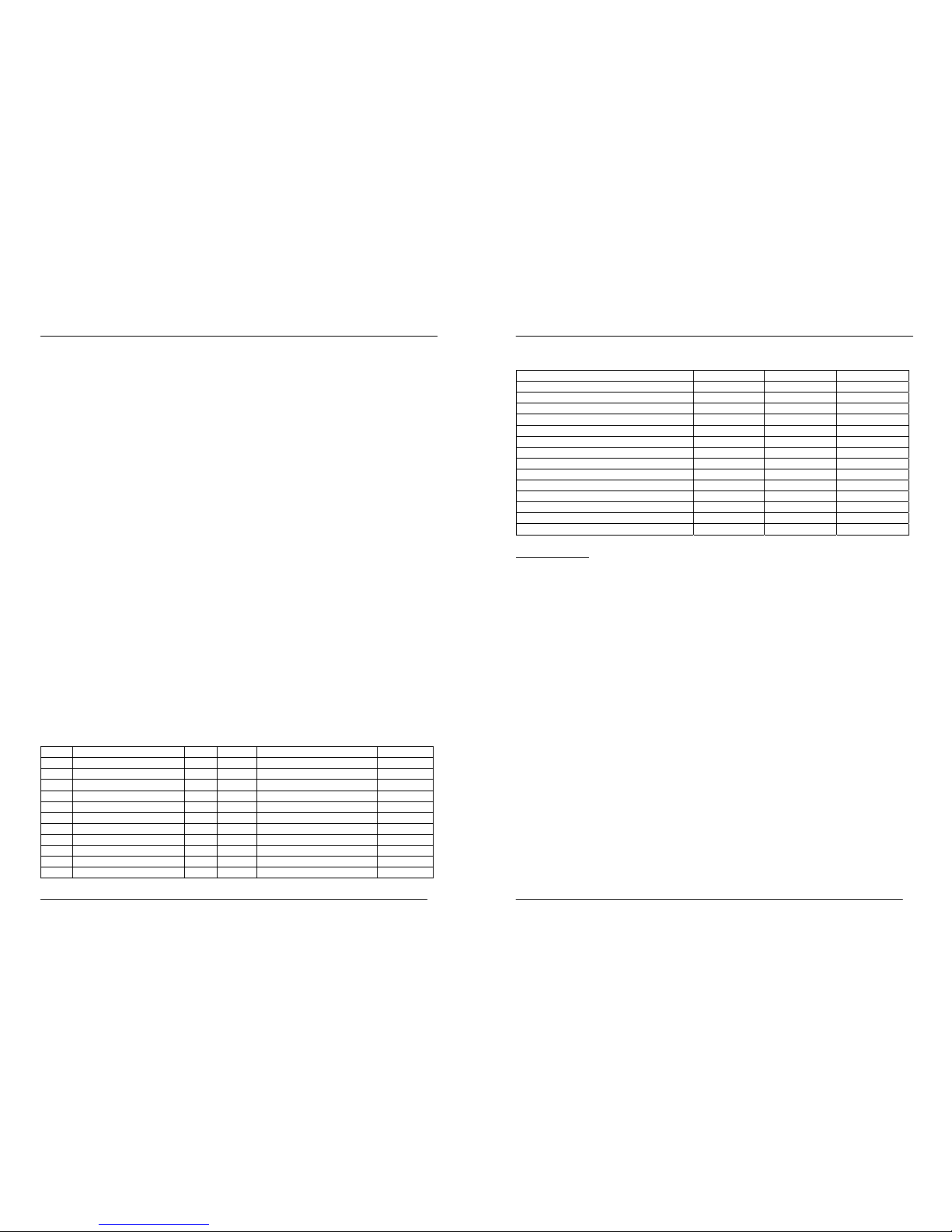
CH13= 000...255 Panel 3 Dimmer BLUE
CH14= 000...255 Panel 3 Master Dimmer
CH15= 000...255 Panel 3 Strobe
CH16= 000…255 Panel 4 Dimmer RED
CH17= 000…255 Panel 4 Dimmer GREEN
CH18= 000...255 Panel 4 Dimmer BLUE
CH19= 000...255 Panel 4 Master Dimmer
CH20= 000...255 Panel 4 Strobe
dFP = Full Preset Mode
Function: 4 channels: Mode/Pattern | Dimmer | Color/Speed | Strobe
The unit receives DMX values on a packet of 4 consecutive DMX channels, with the
following functional assignment:
CH1 = Choice of fixed colors (if CH3 < 25) or fade/switch pattern presets (if CH3 ≥25)
CH2 = 000…255 Master Dimmer 0…100%
CH3 = Function choice C (Color – static) and A (Auto) mode, speed setting for A mode.
CH3 0……24 selects the fixed color (C) mode. Color choice by CH1.
CH3 25......234 selects the auto (A) mode and determines the speed. Pattern choice
by CH1.
CH3 235…255 selects the sound-to-light (S) mode. Pattern choice by CH1.
CH4 = 000…049 Strobe off, 050…255 Strobe rate (050=slow / 255=max. speed 23 Hz)
DMX Reverse Function
Press the MODE button on until the display shows “dIn”. Using the UP/DOWN buttons,
a choice between ON and OFF can be made. This choice applied globally to any
chosen DMX mode and will invert the channel sequence when chosen as “ON”.
Display on/off
The display of the unit will turn off after 25 seconds of not receiving any user
commands through the user interface buttons. On the first hit of any button, the display
will light up again; this first hit will not change any settings, only when you press any
button after that, settings will be affected.
Infrared Remote Control (IRC)
As an optional accessory, this unit can be accompanied by an infrared (IR) remote
control. Please note that all versions of this product are fitted with the required IR
receiver, in this case the following functional description may not be applicable to your
product; in other configurations, the IR receiver may be fitted but the remote control unit
needs to be purchased separately and is not part of the delivery of this unit. You may
contact your distributor/dealer for details.

User Manual: VersoClub-HT3012
V2.00 (01-2014) 16
d16 = DMX 16-Channel Mode
Function: 3 colors RGB + combined master/strobe (4 channels) for each panel
The unit receives DMX values on a packet of 16 consecutive DMX channels, with the
following functional assignment:
CH1 = 000…255 Panel 1 Dimmer RED
CH2 = 000…255 Panel 1 Dimmer GREEN
CH3 = 000...255 Panel 1 Dimmer BLUE
CH4 = Panel 1 Master Dim / Strobe
000…127 Master Dimmer 0…100%
128…227 Strobe speed (128=slow / 227=max. speed 23 Hz)
228…255 Master Dimmer = 100% Strobe off
CH5 = 000…255 Panel 2 Dimmer RED
CH6 = 000…255 Panel 2 Dimmer GREEN
CH7 = 000...255 Panel 2 Dimmer BLUE
CH8 = Panel 2 Master Dim / Strobe
000…127 Master Dimmer 0…100%
128…227 Strobe speed (128=slow / 227=max. speed 23 Hz)
228…255 Master Dimmer = 100% Strobe off
CH9 = 000…255 Panel 3 Dimmer RED
CH10 = 000…255 Panel 3 Dimmer GREEN
CH11= 000...255 Panel 3 Dimmer BLUE
CH12= Panel 3 Master Dim / Strobe
000…127 Master Dimmer 0…100%
128…227 Strobe speed (128=slow / 227=max. speed 23 Hz)
228…255 Master Dimmer = 100% Strobe off
CH13 = 000…255 Panel 4 Dimmer RED
CH14 = 000…255 Panel 4 Dimmer GREEN
CH15 = 000...255 Panel 4 Dimmer BLUE
CH16= Panel 4 Master Dim / Strobe
000…127 Master Dimmer 0…100%
128…227 Strobe speed (128=slow / 227=max. speed 23 Hz)
228…255 Master Dimmer = 100% Strobe off
d20 = DMX 20-Channel Mode
Function: 3 colors RGB + master + strobe (5 channels) for each panel
The unit receives DMX values on a packet of 20 consecutive DMX channels, with the
following functional assignment:
CH1 = 000…255 Panel 1 Dimmer RED
CH2 = 000…255 Panel 1 Dimmer GREEN
CH3 = 000...255 Panel 1 Dimmer BLUE
CH4 = 000...255 Panel 1 Master Dimmer
CH5 = 000...255 Panel 1 Strobe
CH6 = 000…255 Panel 2 Dimmer RED
CH7 = 000…255 Panel 2 Dimmer GREEN
CH8 = 000...255 Panel 2 Dimmer BLUE
CH9 = 000...255 Panel 2 Master Dimmer
CH10= 000...255 Panel 2 Strobe
CH11= 000…255 Panel 3 Dimmer RED
CH12= 000…255 Panel 3 Dimmer GREEN
User Manual: VersoClub-HT3012
V2.00 (01-2014) 5
■Health advice
This unit produces and absorbs electromagnetic radiation. The strength of radiation and
the sensitivity for disturbing interference matches the CE and FCC requirements. A
corresponding sign is printed on the backside of the unit. Any change or modification
may affect the behavior of the unit concerning electromagnetic radiation, with the CE
requirements eventually not to be met any more. The manufacturer takes no
responsibility in this case.
■Functional advice
This unit is immune to the presence of electromagnetic disturbances – both conducted
and radiated - up to a certain level. Under peak conditions, the unit is classified to show
a “class C” performance criteria and may encounter temporary degradation or loss of
function which may need manual help to recover. In such case, disconnect the AC
power from the unit and reconnect it again to recover.
■Environmental advice
This unit is built to conform to the ROHS standards and the WEEE
directive 2002/96/EC of the European Parliament and of the Council of
the European Union. Under these regulations, the product shall not be
discarded into regular garbage at the end of its life, but shall be returned
to authorized recycling stations.
■LED Lifetime advice
LED lifetime is determined by the gradually declining brightness of a LED over time,
with a point of 50% brightness reduction marking the defined end of its lifetime. The
driving factor of this effect is the heat that the chip inside the LED is exposed to. While
a chip may under ideal circumstances reach to more than 100000 hours of lifetime, the
real-world lifetime may only be 30000 to 50000 hours or less if the LED is exposed to
excessive heat, which can be caused by continuously running all LEDs inside this
device at full power and operating the unit in high environmental temperatures. If
improving the lifespan expectancy is a priority, take care of providing for lower
operational temperatures. This may include forced external cooling and/or the reduction
of overall projection intensity.
■Unpacking
Please check that the box contains the following items, and contact your dealer
immediately for replacement if any part is missing:
Main parts: 1 pc. VersoClub-HT3012 main unit
1 pc. mains cable
1 pc. operation manual

User Manual: VersoClub-HT3012
V2.00 (01-2014) 6
■Getting started: choosing a location
Risk of fire: The VersoClub-HT3012 has been designed to work in dry
indoor environments at environmental temperatures of up to 35 degrees
Celsius. For proper operation, the unit must be operated with
unobstructed air convection to its outside metal case.
Do not:
- Operate the VersoClub-HT3012 in environments with more than 35 degrees
environmental temperature or more than 75% relative humidity.
- Operate the VersoClub-HT3012 in any closed environment smaller than
10cbm, unless forced air convection is provided.
■Getting started: secure mounting
The VersoClub-HT3012 can be mounted in various ways:
Floor standing operation (with tripod)
The VersoClub-HT3012 is designed to be mounted on a tripod with 35mm tube
diameter. It can both be mounted on top as well as in any other height on the tripod
tube. Make sure that the diameter of the inserted tripod tube is not less than 35mm as
otherwise secure mounting cannot be granted. Slide the tripod adaptor over the tripod
tube to full extent and secure the unit with the provided screw handle.
User Manual: VersoClub-HT3012
V2.00 (01-2014) 15
dC3 = DMX Combined 3CH Mode
Function: 3 colors RGB (3 channels) for all panels
The unit receives DMX values on a packet of 3 consecutive DMX channels, with the
following functional assignment:
CH1 = 000…255 Dimmer RED (all segments)
CH2 = 000…255 Dimmer GREEN (all segments)
CH3 = 000...255 Dimmer BLUE (all segments)
dC4 = DMX Combined 4CH Mode
Function: 3 colors RGB + combined master/strobe for all panels
The unit receives DMX values on a packet of 4 consecutive DMX channels, with the
following functional assignment:
CH1 = 000…255 Dimmer RED (all segments)
CH2 = 000…255 Dimmer GREEN (all segments)
CH3 = 000...255 Dimmer BLUE (all segments)
CH4 = Master Dimmer / Strobe (all segments)
000…127 Master Dimmer 0…100%
128…227 Strobe speed (128=slow / 227=max. speed 23 Hz)
228…255 Master Dimmer = 100% Strobe off
dC5 = DMX Combined 5CH Mode
Function: 3 colors RGB + separate master/strobe for all panels
The unit receives DMX values on a packet of 5 consecutive DMX channels, with the
following functional assignment:
CH1 = 000…255 Dimmer RED (all segments)
CH2 = 000…255 Dimmer GREEN (all segments)
CH3 = 000...255 Dimmer BLUE (all segments)
CH4 = 000...255 Master Dimmer (all segments)
CH5 = 000...255 Strobe (all segments)
d12 = DMX 12-Channel Mode
Function: 3 colors RGB (3 channels) for each panel
The unit receives DMX values on a packet of 12 consecutive DMX channels, with the
following functional assignment:
CH1 = 000…255 Panel 1 Dimmer RED
CH2 = 000…255 Panel 1 Dimmer GREEN
CH3 = 000...255 Panel 1 Dimmer BLUE
CH4 = 000…255 Panel 2 Dimmer RED
CH5 = 000…255 Panel 2 Dimmer GREEN
CH6 = 000...255 Panel 2 Dimmer BLUE
CH7 = 000…255 Panel 3 Dimmer RED
CH8 = 000…255 Panel 3 Dimmer GREEN
CH9 = 000...255 Panel 3 Dimmer BLUE
CH10 = 000…255 Panel 4 Dimmer RED
CH11 = 000…255 Panel 4 Dimmer GREEN
CH12 = 000...255 Panel 4 Dimmer BLUE
Note: This mode serves as the primary slave mode setting. No specific slave mode is
provided.

User Manual: VersoClub-HT3012
V2.00 (01-2014) 14
A4 (fading) | A14 (switching) | S4 (S2L fading) | S14 (S2L switching)
A color-fill/Blink pattern. Transition is switching in Switch Pattern mode, and
fading in Fade pattern mode.
A5 (fading) | A15 (switching) | S5 (S2L fading) | S15 (S2L switching)
A Fork22 pattern with all 4 panels on. Transition is switching in Switch Pattern
mode, and fading in Fade pattern mode.
A6 (fading) | A16 (switching) | S6 (S2L fading) | S16 (S2L switching)
A 1C Pingpong pattern. Transition is switching in Switch Pattern mode, and
fading in Fade pattern mode.
A7 (fading) | A17 (switching) | S7 (S2L fading) | S17 (S2L switching)
A 4C Pingpong pattern. Transition is switching in Switch Pattern mode, and
fading in Fade pattern mode.
A8 (fading) | A18 (switching) | S8 (S2L fading) | S18 (S2L switching)
A Frame22 pattern. Transition is switching in Switch Pattern mode, and fading
in Fade pattern mode.
A9 (fading) | S9 (S2L fading) | S19 (S2L switching)
A 4-step pattern. Transition is switching in Switch Pattern mode, and fading in
Fade pattern mode.
A19 (switching+strobe) :
A Strobe pattern. All panels strobe at the same time, with alternating colors.
A20: white strobe
A21: red strobe
A22: green strobe
A23: blue strobe
DMX Modes
Press the MODE button on the unit itself until the display shows any of the below
options, which are displayed consecutively, indicating operation in the chosen DMX
mode. You then can choose any DMX starting address by simply using the UP/DOWN
buttons on the unit itself. The chosen DMX-address becomes effective approximately 3
seconds later and will show up on the display on the unit itself in alternation to the
indicator of the chosen mode. This allows control of the unit by any external DMX signal
sending on the chosen channels. Once such signal is received, a LED on the lower
right side of the “d” in the display indicates that a DMX signal is present. Once in “d”
Mode, the IR remote control sensor is disabled. Also note that DMX functions cannot
be activated via the optional IR remote.
User Manual: VersoClub-HT3012
V2.00 (01-2014) 7
When using a tripod, make sure that:
•the tripod is erected to a height where the audience can neither accidently nor
intentionally touch it
•the working height is in enough distance to ceiling or other constructions on top to
avoid any heat accumulation
•the working load of the used tripod is sufficient to carry this unit. Do only use
safety-certified tripods.
•the tripod has a locking mechanism against unintentional tube retraction.
•the tripod stands on even and firm ground.
•any cable running to and from the trip is not obstructing pathways of the audience,
and that no any pull force on a cable can make the tripod fall over.
•the tripod base is either out of audience reach or gated with a security fence
•the tripod is placed outside of any evacuation paths.
Risk of injury: Tripod mounting requires related knowledge and
experience, including among others calculating and balancing working
load limits, correct positioning and securing, and periodic safety
inspection. Improper installation can result in body injury. The
manufacturer of this unit does not assume any liability for correct and
secure placement and use of tripods – make sure to comply with local
safety regulations.
Hanging/Rigging, ceiling-mounted operation
Further to the tripod mounting adaptor, the VersoClub-HT3012 is equipped with two
M10 thread insert mounting points on the top of the unit. These can typically be used to
insert truss hooks or other rigging equipment.
Risk of injury: Overhead mounting requires extensive experience,
including among others calculating working load limits, good knowledge
of the installation material being used, and periodic safety inspection of
all installation material and the unit. If you lack such qualifications, do
not attempt the installation yourself. Improper installation can result in
body injury. Be sure to complete all rigging and installation procedures
before applying power to the unit.
•The unit should be installed out of reach of people and outside areas where
persons may walk by or be seated.
•Make sure that the installation area can hold a minimum point load of 10 times the
device’s weight.
•In fixed installations, fix the unit with self-locking screws/nuts to the mounting point.
•When mounting the unit to truss be sure to secure an appropriately rated clamp to
the hanging yoke using a M10 screw fitted through the center hole of the hanging
yoke.

User Manual: VersoClub-HT3012
V2.00 (01-2014) 8
•Where required, secure the installation with an appropriate safety cable. Always
use a certified safety cable according to EN60598-2-17 Section 17.6.6 that can
hold 12 times the weight of the device when installing the unit. This secondary
safety attachment should be installed in a way that no part of the installation can
drop more than 20cm if the main attachment fails.
•Never stand directly below the device when mounting, removing, or servicing the
fixture. Make sure the area below the installation place is free from unwanted
persons during rigging, de-rigging and servicing.
•The operator has to make sure that the safety-relating and machine-technical
installations are approved by an expert before using them for the first time. The
installations should be re-inspected every year.
•Make sure to comply with applicable cooling requirements if any.
■Getting started: making AC supply connections
Risk of fire
/
Safety risk
The VersoClub-HT3012 requires an AC power source with sufficient
power carriage and correct grounding to ensure safe operation. The AC
power source must be equipped with a circuit breaker and earth
leakage detector. Make sure to only use compliant AC supply lines.
The VersoClub-HT3012 has an AC outlet that is designed to carry loads
of no more than 8A. Make sure that all connected devices in a chain fed
by the first device do not exceed a maximum of 8A current
consumption.
■Getting started: making DMX control connections
Connect the VersoClub-HT3012 to a suitable DMX controller where needed, and
interconnect several units by means of their DMX In/Outputs as required. The last unit
shall be equipped with a proper 120 Ohm termination resistor equipped DMX-plug as
shown in below drawing. Please make sure that all used DMX cables comply to below
standard:
User Manual: VersoClub-HT3012
V2.00 (01-2014) 13
The output level (brightness) can be set in 10 levels: 10% | 20% | 30% | 40% | 50% |
60% | 70% | 80% | 90% | 100%. To do this with the on-board user interface, the user
must change into COLOR mode first and make a global brightness adjustment as
described in the COLOR mode chapter. For units fitted with the optional IR remote
control, the brightness can also be set directly using the LEVEL UP/DOWN buttons on
the IR remote.
If the unit is controlled by the optional IR remote control, further parameters apply as
follows:
•When activating the STROBE function (Strobe RED/GREEN/BLUE/WHITE
buttons) on the IR remote control, the unit will return to previously chosen
pattern preset upon pressing the STROBE function on the IR remote again.
Note that the strobe speed is fixed at 16Hz and cannot be changed. Also note
that the strobe function always applies to all panels with the same color.
•Once Blackout is activated by the IR remote control, the previous operation
mode is stored and recalled once Blackout is cleared by pressing the relative
button on the IR remote again.
•The IR remote is only active when the unit is in C, A and S modes. If you
intend to control the unit by IR remote, make sure by relative setting on the
unit itself that the unit is NOT in any DMX mode.
In “S” mode, the unit does not receive any values from the DMX input but generates
related DMX values on the output (12CH) according to the selected pattern, so that
further units can show the same behaviour if they are connected by DMX signal cables
and set to DMX mode “d12” with starting channel = 001. If you leave “S” for any reason
and come back later into any of these modes, the unit will recall the last chosen pattern
(even if the unit was switched off in between).
Patterns for A and S Modes
A0 (fading) | A10 (switching) | S0 (S2L fading) | S10 (S2L switching)
Plays pattern 1/2/3/4/5/6/7/8, each 4 times in a cycle. Transition is switching
in Switch Pattern mode, and fading in Fade pattern mode.
A1 (fading) | A11 (switching) | S1 (S2L fading) | S11 (S2L switching)
A color-change on all panels at the same time. Transition is switching in
Switch Pattern mode, and fading in Fade pattern mode.
A2 (fading) | A12 (switching) | S2 (S2L fading) | S12 (S2L switching)
A ZIP up-down. Transition is switching in Switch Pattern mode, and fading in
Fade pattern mode.
A3 (fading) | A13 (switching) | S3 (S2L fading) | S13 (S2L switching)
A ZIP-Replacement pattern with all 4 panels on, but replacing one color by
another in a ZIP up-down manner. Transition is switching in Switch Pattern
mode, and fading in Fade pattern mode.

User Manual: VersoClub-HT3012
V2.00 (01-2014) 12
The output level (brightness) can be set in 10 levels: 10% | 20% | 30% | 40% | 50% |
60% | 70% | 80% | 90% | 100%. To do this with the on-board user interface, the user
must change into COLOR mode first and make a global brightness adjustment as
described in the COLOR mode chapter. For units fitted with the optional IR remote
control, the brightness can also be set directly using the LEVEL UP/DOWN buttons on
the IR remote.
If the unit is controlled by the optional IR remote control, further parameters apply as
follows:
•When activating the STROBE function (Strobe RED/GREEN/BLUE/WHITE
buttons) on the IR remote control, the unit will return to previously chosen
pattern preset upon pressing the STROBE function on the IR remote again.
Note that the strobe speed is fixed at 16Hz and cannot be changed. Also note
that the strobe function always applies to all panels with the same color.
•Once Blackout is activated by the IR remote control, the previous operation
mode is stored and recalled once Blackout is cleared by pressing the relative
button on the IR remote again.
•The IR remote is only active when the unit is in C, A and S modes. If you
intend to control the unit by IR remote, make sure by relative setting on the
unit itself that the unit is NOT in any DMX mode.
In “A” mode, the unit does not receive any values from the DMX input but generates
related DMX values on the output (12CH) according to the selected pattern, so that
further units can show the same behaviour if they are connected by DMX signal cables
and set to DMX mode “d12” with starting channel = 001. If you leave “A” for any reason
and come back later into any of these modes, the unit will recall the last chosen pattern
(even if the unit was switched off in between).
“S” Sound-to-Light Mode
Press the MODE button on the unit itself until the display shows “Sxx”, indicating
operation in “S” (S2L=sound-to-light) mode. The S Mode contains 20 different patterns,
10 thereof with fading transition (Patterns S0…S9) and 10 thereof with switching
transition (patterns S10…S19). The patterns can be chosen by the UP/DOWN buttons
on the unit itself or for units fitted with the optional IR remote control, via the selection of
S2L mode and then selecting FADE or SWITCH and pressing the respective number
key for pattern selection. For a description of the available patterns, see section
“Patterns for A and S Modes”.
In “S” mode, the pattern progress is driven by the music signal picked up by the internal
microphone in the following way: l
•In pattern presets S0….S9, every detected beat will temporarily speed up the
color fade, creating a “pulsating” effect in synchronization with the music.
•In pattern presets S10….S19, every detected beat will switch to the next
pattern step, creating a “chasing” effect in synchronization with the music.
User Manual: VersoClub-HT3012
V2.00 (01-2014) 9
■Operation
User interface overview:
1 MODE selection button
2 UP-Button
3 DOWN-Button
4 Display showing the Mode, DMX-address, etc.
5 DMX input
6 DMX output
7 AC input
Upon the user’s choice, the unit can work in stand-alone automatic modes, or with fixed
colors, or it may be controlled by an optional infrared (IR) remote control or by external
DMX-controllers. Available modes:
“C” Color Mode
Press the MODE button until the first digit on the display shows “Cxx”, indicating
operation in “C” mode with chosen preset “xx”, then choose by using the UP/DOWN
buttons one of the 20 color presets as shown in the list below. For units fitted with the
optional IR remote control, press the COLOR button on the IR remote respectively; the
first ten color presets (00…09) are available via IR remote by pressing the number keys
0…9 on the IR remote accordingly.
The output level (brightness) can be set in 10 levels: 10% | 20% | 30% | 40% | 50% |
60% | 70% | 80% | 90% | 100%. This is done by pressing and holding the MODE button

User Manual: VersoClub-HT3012
V2.00 (01-2014) 10
and then pressing the UP or DOWN buttons to change the brightness. The current level
is displayed while making the adjustment. Note that the brightness setting using the on-
board user interface can only be done in COLOR mode and is a global setting for all
stand-alone modes, which means that the same chosen brightness remains applicable
for the AUTO mode as well. The brightness chosen on the unit itself however has no
influence in any of the DMX modes. For units fitted with the optional IR remote control,
the brightness can also be set using the LEVEL UP/DOWN buttons. The controls on
the unit itself and on the IR remote supersede each other with the last command given
having validity.
If the unit is controlled by the optional IR remote control, further parameters apply as
follows:
•When activating the STROBE function (Strobe RED/GREEN/BLUE/WHITE
buttons) on the IR remote control from within the C (COLOR) Mode, the unit
will return to the C (COLOR) Mode in previously chosen Color preset upon
pressing the STROBE function on the IR remote again. Note that the strobe
speed is fixed at 16Hz and cannot be changed. Also note that the strobe
function always applies to all 4 panels with the same color.
•Once Blackout is activated by the IR remote control, the previous operation
mode is stored and recalled once Blackout is cleared by pressing the relative
button on the IR remote again.
•The IR remote is only active when the unit is in C and A modes. If you intend
to control the unit by IR remote, make sure by relative setting on the unit itself
that the unit is NOT in any DMX mode.
In “C” mode, the unit does not receive any values from the DMX input but generates
related DMX values on the output (12CH) according to the selected preset, so that
further units can show the same behaviour if they are connected by DMX signal cables
and set to DMX mode “d12” with starting channel = 001. If you leave mode “C” for any
reason and come back later into mode “C”, the unit will recall the last chosen color
preset (even if the unit was switched off in between).
Available color presets:
Unit Color IRC Unit Color IRC
C00 White (W) 0 C11 Turquoise (T) n/a
C01 Red (R) 1 C12 Lime (L) n/a
C02 Green (G) 2 C13 Marine (M) n/a
C03 Blue (B) 3 C14 Frog (F) n/a
C04 Orange (O) 4 C15 Lavender (V) n/a
C05 Pink (P) 5 C16 Candy (C) n/a
C06 Green-Blue (GBGB) 6 C17 Turquoise Lime (TLTL) n/a
C07 Red-Blue (RBRB) 7 C18 Lavender Candy (LCLC) n/a
C08 Orange-Green (OGOG) 8 C19 White-Red (WRWR) n/a
C09 Pink-Blue (PBPB) 9 C20 OFF Blackout
C10 Yellow
User Manual: VersoClub-HT3012
V2.00 (01-2014) 11
Color Definitions (in DMX values) as below:
Colour R G B
White (W) 255 255 255
Red (R) 255 0 0
Green (G) 0 255 0
Blue (B) 0 0 255
Yellow (Y) 255 170 0
Pink (P) 255 0 255
Turquoise (T) 0 255 255
Lime (L) 127 255 0
Orange (O) 255 85 0
Marine (M) 0 127 255
Frog (F) 0 255 127
Lavender (V) 127 0 255
Candy (C) 255 0 127
Blackout 0 0 0
“A” Auto Mode
Press the MODE button on the unit itself until the display shows “Axx”, indicating
operation in “A” mode. The A Mode contains 24 different patterns, 10 thereof with
fading transition (Patterns A0…A9) and 10 thereof with switching transition (patterns
10…19) and 4 thereof as strobe patterns (patterns 20…23). The patterns can be
chosen by the UP/DOWN buttons on the unit itself or for units fitted with the optional IR
remote control, via the selection of AUTO mode and then selecting FADE or SWITCH
and pressing the respective number key for pattern selection. For a description of the
available patterns, see section “Patterns for A and S Modes”.
The units will run on a fixed speed can be changed in 10 steps by two different ways:
•by pressing the MENU button on the unit itself for two seconds or longer – the
display then (instead of going to the next menu) jumps to speed setting mode
and shows the below choices, which can be chosen by the UP and DOWN
buttons. Once the desired speed is set, release the MENU button. Note that
the speed setting using the on-board user interface can only be done in AUTO
mode.
•by the IR remote control where the 10 speed levels SP0…SP9 can be chosen
with the SPPED UP and SPPED DOWN buttons
The controls on the unit itself and on the IR remote supersede each other with the last
command given having validity.
Note: if instead of a fixed speed the unit is supposed to run in Sound-to-light (S2L)
mode, the “S” mode must be chosen or the SOUND button. On the IRC must be
pressed.
Table of contents
Other Multiform Dj Equipment manuals