6
-
lásba, majd az óramutató járásával ellentétes irányba forgassuk
-
FONTOS!
-
-
-
részt, ezzel kiakasztjuk ezeket a falból, majd vegyük ki ezeket a
hátsó nyílásokból. Puha, jól felhígított ammóniás oldattal megned-
-
-
-
egyéb maró hatású anyagok használatát, különösen a lakkréteg-
-
tén kárt tehetnek a felületi rétegekben.
-
-
AQUASMART RENDSZERREL
• The alarm has three tone positions, low, medium and high. To
adjust the tone, check that the timer is in the manual mode, then
press the button and hold down to hear the tone selected. On re-
leasing the button , press again and hold down to select another
tine. Repeat the procedure until the required tone is heard.
WARNING! a power cut will result in the programmed func-
tions to be cancelled, including the clock. Once the power
returns three ashing zeros will appear and the oven can be
re-programmed.
USING THE MECHANICAL TIMER
Once the thermostat controls are in the desired position, turn
the knob clockwise to the maximum position and then turn it
anti-clockwise to the desired time; at the end of this set time
the buzzer will sound. The timer only indicates the end of the
set time, but it does not stop the function being used.
CLEANING THE APPLIANCE
IMPORTANT
As a safety precaution, before beginning to clean the oven al-
ways unplug it from the power supply or remove the appliance
power lead.
Cleaning an oven that does not self-cleaning panels must be
done after use, when it is switched off but still warm, not hot, so
that the film of grease produced by the cooking vapours on the
walls is still easy to remove, as well as the drips and splashes
of fat that are not yet hard and dry.
Remove the chrome-plated wire side supports; pull the front part
upwards to unattach them from the wall and remove them from
the rear orifices. Clean the oven with a soft cloth soaked in a di-
luted ammoniac solution; rinse and dry. If there are still stains and
splashes, place a damp cloth soaked in ammoniac at the back,
close the door and, after a few hours, wash the oven with warm
water and liquid detergent, rinse and dry carefully. To clean the
shiny metal outside doors, use a soft cloth with soap and water; do
not use any powdered products that contain abrasive substances.
Also avoid the use of acid or alkaline substances (lemon juice,
vinegar, salt, tomatoes, etc.). Avoid using products containing
chlorine, acid or abrasive substances specially for cleaning
the varnished walls. Do not use thick steel wool or hard uten-
sils, as they can damage the surface finishes.
Do not use high pressure cleaners or steam appliances for
cleaning the oven.
Normally, wiping with a damp soft cloth and warm detergent is
enough, but for stubborn stains the following is recommended:
OVEN CLEANING SYSTEM EQUIPPED WITH THE AQUAS-
MART SYSTEM
1 Take out the internal components: tray, screen, side screens.
2 Pour 200 ml of soapy water on the bottom of the oven
3. Turn on and set the oven at 200º for 15 minutes
4. Move thetemperaturecontrol from 200ºC to 0ºC. Let the oven
cool down for 20 minutes.
5. Move the AquaSmart function to 0. Wipe clean with a rag
or soft cloth.
VITRIFIED ENAMELLED PARTS
Only use a recommended cleaner for this type of material –
avoid chloride-based products such as bleach.
GLASS DOOR PANEL
Do not use abrasive products which could damage the glass.
Remember that if the surface of the glass panel becomes
scratched, it could cause a dangerous failure.
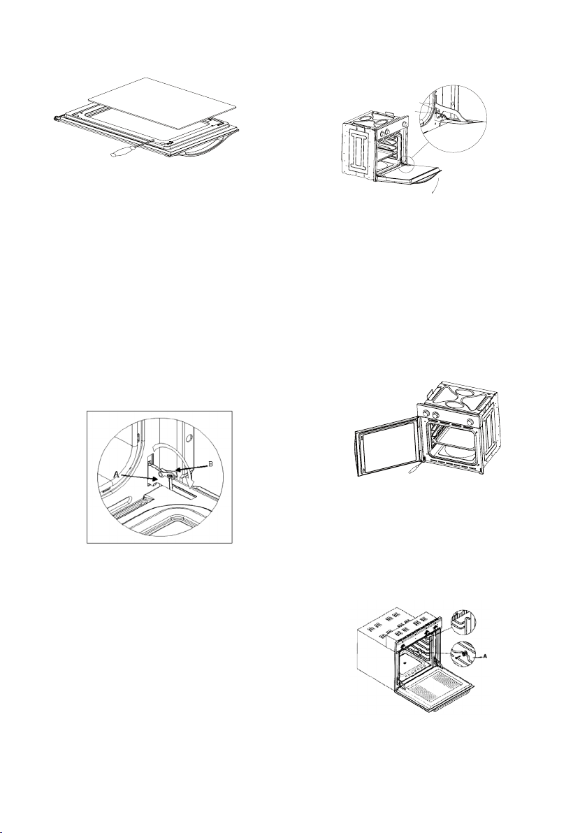
To simplify the cleaning, the inner glass panel can be taken out
of the door. The method for removing the glass from the three
types of door is shown below.
Door type A
After removing the screws fixing the glass, located on the inner
face of the door, lift the glass out carefully. In versions with
three glasses the intermediate glass can also be removed. The
procedure is the same as above.
Door type B1 / B2
After removing the screws fixing the upper support of the
glass, remove the support in direction “A”. Then the glass can
be pulled out. In versions with three glasses the intermediate
glass can also be removed.
A
A
-
vel töröljük át a készüléket.
Kizárólag kifejezett ilyen anyagokhoz ajánlott tisztítószert használ-
-
válik, az veszélyes meghibásodáshoz vezethet.
az ajtóból. Az alábbiakban kerül bemutatásra az üvegbetét kivé-
A
-
-
B1 és B2
-
• The alarm has three tone positions, low, medium and high. To
adjust the tone, check that the timer is in the manual mode, then
press the button and hold down to hear the tone selected. On re-
leasing the button , press again and hold down to select another
tine. Repeat the procedure until the required tone is heard.
WARNING! a power cut will result in the programmed func-
tions to be cancelled, including the clock. Once the power
returns three ashing zeros will appear and the oven can be
re-programmed.
USING THE MECHANICAL TIMER
Once the thermostat controls are in the desired position, turn
the knob clockwise to the maximum position and then turn it
anti-clockwise to the desired time; at the end of this set time
the buzzer will sound. The timer only indicates the end of the
set time, but it does not stop the function being used.
CLEANING THE APPLIANCE
IMPORTANT
As a safety precaution, before beginning to clean the oven al-
ways unplug it from the power supply or remove the appliance
power lead.
Cleaning an oven that does not self-cleaning panels must be
done after use, when it is switched off but still warm, not hot, so
that the film of grease produced by the cooking vapours on the
walls is still easy to remove, as well as the drips and splashes
of fat that are not yet hard and dry.
Remove the chrome-plated wire side supports; pull the front part
upwards to unattach them from the wall and remove them from
the rear orifices. Clean the oven with a soft cloth soaked in a di-
luted ammoniac solution; rinse and dry. If there are still stains and
splashes, place a damp cloth soaked in ammoniac at the back,
close the door and, after a few hours, wash the oven with warm
water and liquid detergent, rinse and dry carefully. To clean the
shiny metal outside doors, use a soft cloth with soap and water; do
not use any powdered products that contain abrasive substances.
Also avoid the use of acid or alkaline substances (lemon juice,
vinegar, salt, tomatoes, etc.). Avoid using products containing
chlorine, acid or abrasive substances specially for cleaning
the varnished walls. Do not use thick steel wool or hard uten-
sils, as they can damage the surface finishes.
Do not use high pressure cleaners or steam appliances for
cleaning the oven.
Normally, wiping with a damp soft cloth and warm detergent is
enough, but for stubborn stains the following is recommended:
OVEN CLEANING SYSTEM EQUIPPED WITH THE AQUAS-
MART SYSTEM
1 Take out the internal components: tray, screen, side screens.
2 Pour 200 ml of soapy water on the bottom of the oven
3. Turn on and set the oven at 200º for 15 minutes
4. Move the temperature control from 200ºC to 0ºC. Let the oven
cool down for 20 minutes.
5. Move the AquaSmart function to 0. Wipe clean with a rag
or soft cloth.
VITRIFIED ENAMELLED PARTS
Only use a recommended cleaner for this type of material –
avoid chloride-based products such as bleach.
GLASS DOOR PANEL
Do not use abrasive products which could damage the glass.
Remember that if the surface of the glass panel becomes
scratched, it could cause a dangerous failure.
To simplify the cleaning, the inner glass panel can be taken out
of the door. The method for removing the glass from the three
types of door is shown below.
Door type A
After removing the screws fixing the glass, located on the inner
face of the door, lift the glass out carefully. In versions with
three glasses the intermediate glass can also be removed. The
procedure is the same as above.
Door type B1 / B2
After removing the screws fixing the upper support of the
glass, remove the support in direction “A”. Then the glass can
be pulled out. In versions with three glasses the intermediate
glass can also be removed.
A
A
FONTOS:
1.A sütőajtó tisztítási célzattal való szétszerelése után különös figyelmet fordítson az összeszerelésre! A belső
üveglapot a festett kerettel kifelé helyezze vissza a helyére, mert nem érintkezhet a festett felület a sütő
tömítésével, amire az ajtó csukott állapotában felfekszik.
2.Bizonyos modelleknél „Az ajtó szétszerelése és tisztítása után, ha visszahelyezi az üveget az ajtóba, ügyeljen, hogy
az üvegen lévő OK felirat felül legyen, az ajtó kivett állapotában, ha a sütőtér felé fordított üveget nézzük, akkor
balról jobbra olvashatóan (OK). Az ajtó visszaszerelése után, ha az ajtót lenyitjuk, az ajtó fölé állva pedig
tükörírással legyen olvasható az OK szó.