Munsch MPC-B series User manual

Standard Chemical Pump
Operating instructions MPC-B series
Version BA-2006.03
Print-No. 01
VM-No. EN
Munsch Chemie-Pumpen GmbH
Im Staudchen
56235 Ransbach-Baumbach
Germany
Phone: +49 (0) 26 23-8 98-90
Fax: +49 (0) 26 23-8 98-95
E-mail: [email protected]
Internet: http://www.munsch.de
We reserve the right to make technical changes.

Table of contents
Table of contents
1 About this document ............................... 4
1.1 Target groups ................................. 4
1.2 Other applicable documents ................ 4
1.3 Warnings and symbols ....................... 5
1.4 Technical terms ............................... 5
2Security .............................................. 6
2.1 Intended use .................................. 6
2.2 General safety instructions .................. 6
2.2.1 Product safety ................................ 6
2.2.2 Operator's obligations ........................ 7
2.2.3 Duties of the operating staff ................. 7
2.3 Special hazards .............................. 7
2.3.1 Potentially explosive areas .................. 7
2.3.2 Hazardous pumped liquids .................. 7
2.3.3 Magnetic field ................................. 7
3 Layout and function ................................ 8
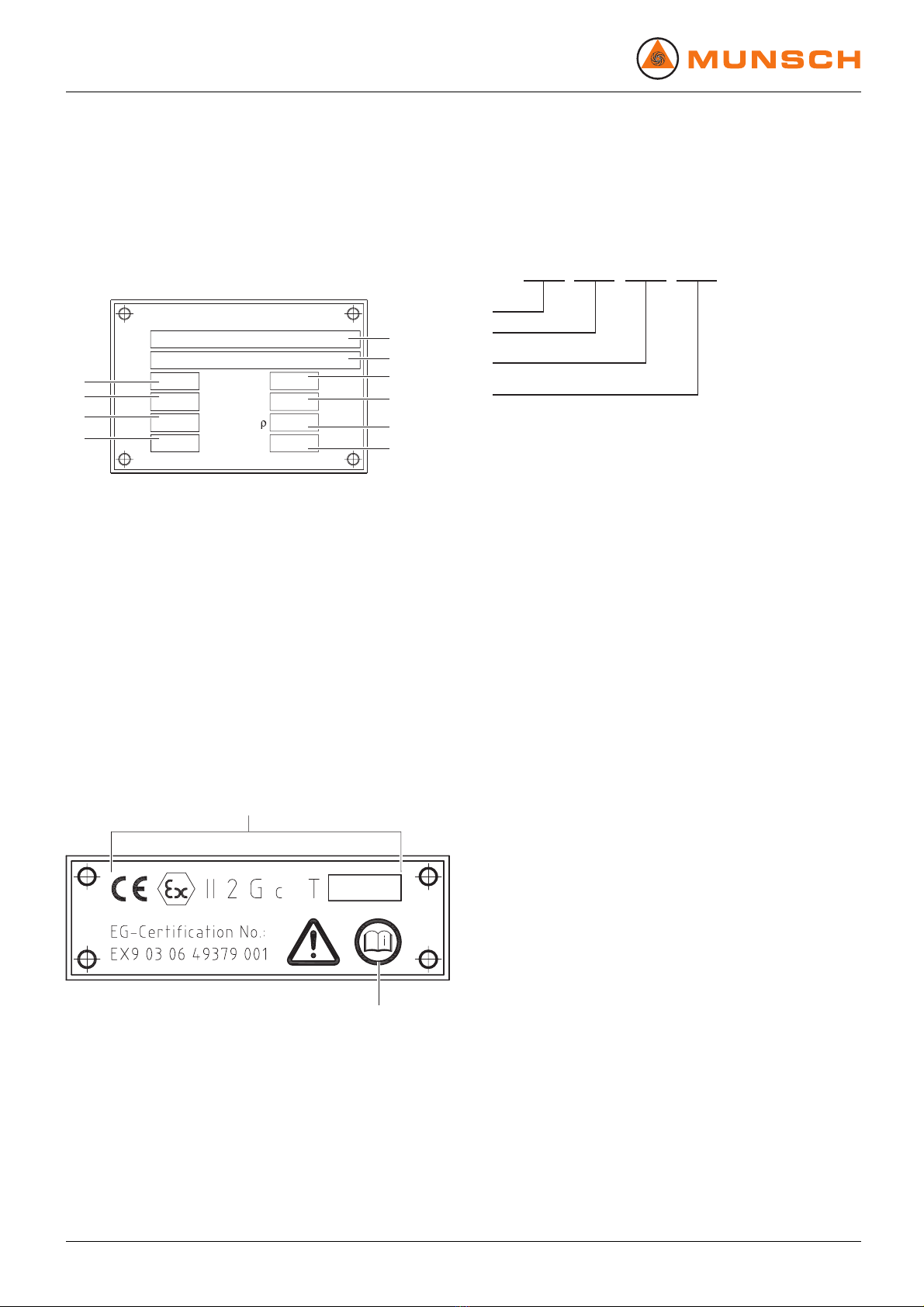
3.1 Labels ......................................... 8
3.1.1 Type plate ..................................... 8
3.1.2 ATEX plate .................................... 8
3.1.3 Pump type code .............................. 8
3.2 Layout ......................................... 9
4 Transport, storage and disposal .................. 10
4.1 Transport ...................................... 10
4.1.1 Unpacking and inspection on delivery . ..... 10
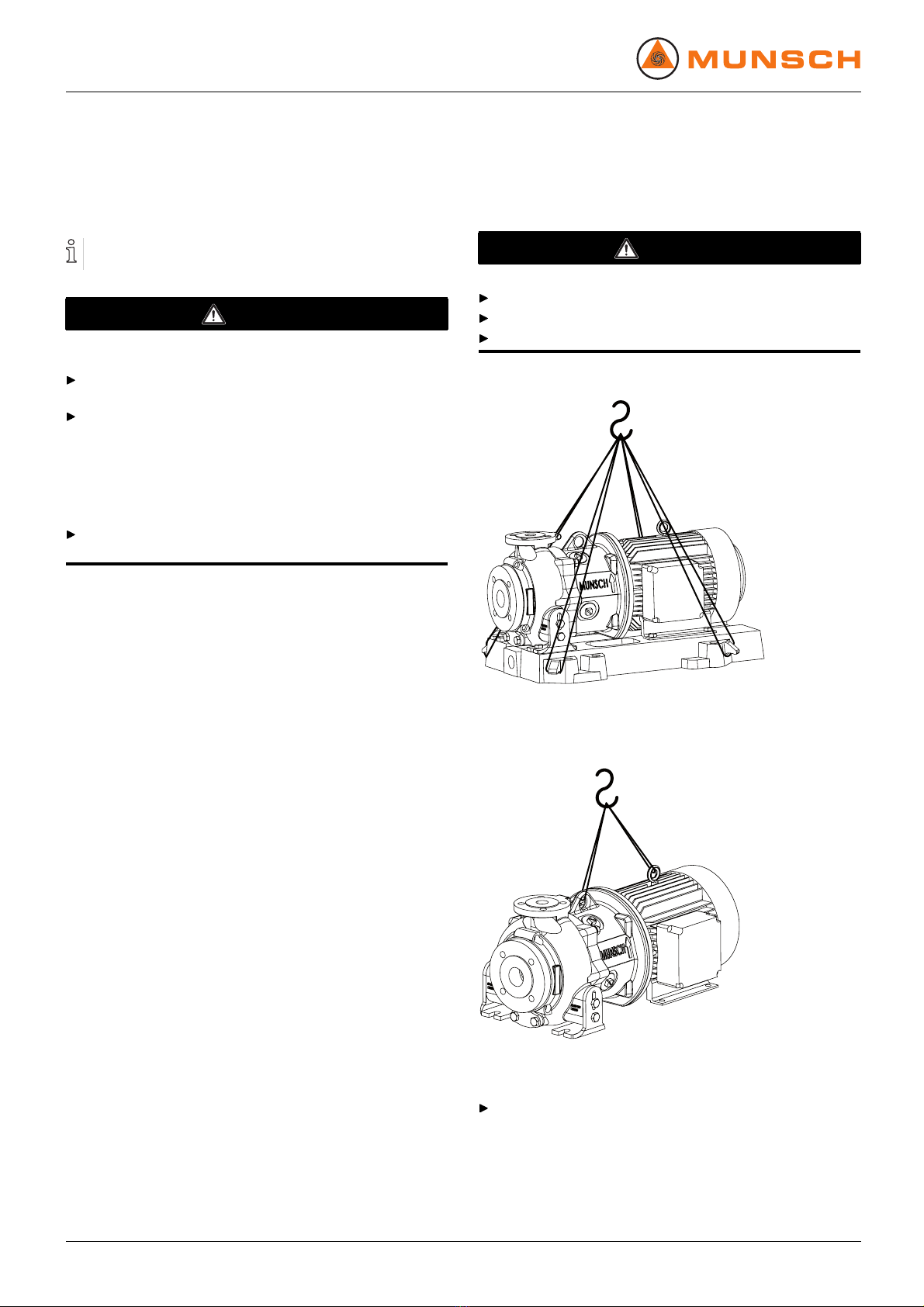
4.1.2 Lifting .......................................... 10
4.2 Preservation .................................. 11
4.3 Storage ....................................... 11
4.4 Disposal ....................................... 11
5 Setup and connection .............................. 12
5.1 Preparing the installation .................... 12
5.1.1 Checking the ambient conditions ... . .. . . .. . 12
5.1.2 Preparing the installation site ............... 12
5.1.3 Preparing the foundation and setup
surface ........................................ 12
5.1.4 Preparing the pump .......................... 12
5.1.5 Installing the heat insulation .. .. . . .. . . .. . ... . 12
5.2 Setup with foundation ........................ 13
5.2.1 Setting the pump group down on the
foundation .................................... 13
5.2.2 Fastening the pump group .................. 13
5.3 Setup without foundation .................... 14
5.4 Planning the pipes ........................... 14
5.4.1 Avoid impurities in the pipes ................. 14
5.4.2 Laying out supportsandflange
connections ................................... 14
5.4.3 Specifying nominal diameters ............... 14
5.4.4 Determining pipe lengths .................... 15
5.4.5 Optimising cross-section and direction
changes ....................................... 15
5.4.6 Providing safety and monitoring devices
(recommended) .............................. 15
5.5 Connecting the pipes ........................ 15
5.5.1 Installing auxiliary pipes ..................... 15
5.5.2 Installing the suction pipe .................... 16
5.5.3 Installing the pressure pipe .................. 16
5.5.4 Checking that the pipe connections are
stress-free .................................... 16
5.6 Connecting the electrical system . ... ... ... . 16
5.6.1 Connecting the motor ........................ 16
5.6.2 Checking the direction of rotation .. . . .. . ... . 16
6Operation ............................................ 17
6.1 Preparations for the initial start-up ... . .. . . .. 17
6.1.1 Identifying the pump version ................ 17
6.1.2 Checking downtimes ......................... 17
6.1.3 Preparing auxiliary operating systems . . . .. . 17
6.1.4 Filling and bleeding .......................... 17
6.1.5 Checking the direction of rotation .. . . .. . ... . 17
6.2 Putting the pump into service ............... 18
6.2.1 Switching on the pump ...................... 18
6.2.2 Switching off the pump ....................... 19
6.3 Shut-down .................................... 19
6.4 Restoring the pump to service .............. 20
6.5 Operating the stand-by pump ............... 20
7 Maintenance ......................................... 21
7.1 Inspections ................................... 21
7.2 Maintenance .................................. 22
7.3 Dismounting .................................. 23
7.3.1 Returning the pump to the manufac-
turer ........................................... 23
7.3.2 Preparing the dismounting .................. 24
7.3.3 Undoing connections (if available) ... . .. . . .. 24
7.3.4 Pulling off the volute casing ................. 24
7.3.5 Dismounting the impeller, plain bearing
bracket and pump rotor ...................... 24
7.3.6 Dismounting the drive rotor .................. 26
7.4 Installing ...................................... 26
7.4.1 Preparing the installation .................... 26
7.4.2 Installing the drive rotor ...................... 26
7.4.3 Installing the plain bearing bracket .. . ... . .. 27
7.4.4 Fitting the pump in the installation .......... 27
7.5 Ordering spare parts ......................... 27
8 Disturbance recovery .............................. 28
9 Appendix ............................................. 31
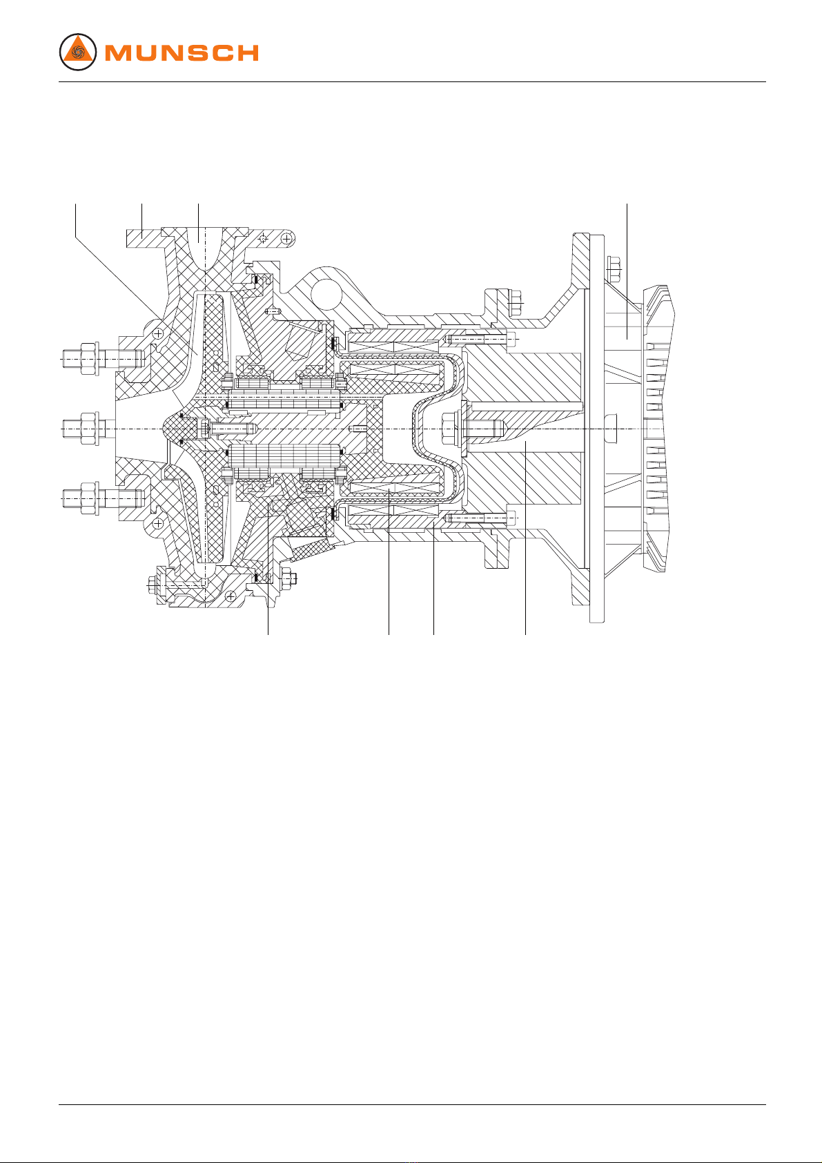
9.1 Sectional drawing ............................ 31
9.1.1 Part numbers and designations ... . .. . ... . .. 31
9.1.2 Overview sectional drawing ................. 32
9.1.3 Variants ....................................... 33
9.2 Technical specifications ...................... 33
9.2.1 Ambient conditions ........................... 33
9.2.2 Noise pressure level ......................... 33
9.2.3 Tightening torques ........................... 34
2 MPC-B series BA-2006.03 EN – 01

Table of contents
9.2.4 Cleaning agents .............................. 34
9.2.5 Socket loads according to ISO 5199 .. . ... . 34
9.3 Spare parts for two years of continuous
operation according to DIN 24296 . . .. . ... . . 35
List of figures
Fig. 1 Type plate (example) ........................ 8
Fig. 2 ATEX plate (example) ........................ 8
Fig. 3 Pump type code (example) .................. 8
Fig. 4 MPC-B layout ................................. 9
Fig. 5 Fastening the lifting gear to the pump
group .......................................... 10
Fig. 6 Fastening the lifting gear to the pump ... . .. 10
Fig. 8 Setup without foundation .................... 14
Fig. 9 Straight pipe lengths in front of and behind
the pump (recommended) ................... 15
Fig. 10 Undoing the flushing connector ............. 24
Fig. 11 Pulling off the volute casing ................. 24
Fig. 12 Undoing the impeller screw ................. 24
Fig. 15 Dismounting the drive rotor .................. 26
Fig. 16 Installing the plain bearing bracket .. . . .. . .. 27
Fig. 17 MPC-B – overview sectional drawing .. . . .. . 32
Fig. 18 MPC-B – housing foot ....................... 32
Fig. 19 Emptying (optional) .......................... 33
Fig. 20 Fluid connection (optional) .................. 33
Fig. 21 Socket loads at the pump ................... 34
List of tables
Tab. 1 Target groups and their duties .. . . .. . ... . . .. 4
Tab. 2 Other applicable documents and their
purpose ....................................... 4
Tab. 3 Warnings and consequences of
non-observance .............................. 5
Tab. 4 Symbols and their meaning ................. 5
Tab. 5 Technical terms and their meaning . .. . .. . . . 5
Tab. 6 Measures after long storage times/
downtimes .................................... 12
Tab. 7 Measures to be taken if operation is
interrupted .................................... 19
Tab. 8 Measures to be taken, depending on the
pumped liquid behaviour .................... 19
Tab. 9 Measures for return .......................... 23
Tab. 10 Fault/number assignment ................... 28
Tab. 11 Troubleshooting table ........................ 30
Tab. 12 Designation of components according to part
numbers ...................................... 31
Tab. 13 Ambient conditions ........................... 33
Tab. 14 Noise pressure level ......................... 33
Tab. 15 Steel/cast pairings ........................... 34
Tab. 16 Socket head cap screw 914.1 -steel/steel
pairing ......................................... 34
Tab. 17 Cleaning agents .............................. 34
Tab. 18 Socket loads .................................. 34
Tab. 19 Socket loads – torques ...................... 34
Tab. 20 Spare parts for two years of continuous
operation ...................................... 35
EN – 01 BA-2006.03 MPC-B series 3

About this document
1 About this document
This manual
• Ispartofthepump
• Applies to all of the afore-mentioned series
• Describes safe and appropriate operation during all oper-
ating phases
1.1 Target groups
Target group Duty
Operating company Keep this manual available where the installation is used, including
for later use.
Make sure the staff read and follow these instructions and the
other applicable documents, especially all safety instructions and
warnings.
Observe any additional rules and regulations referring to the
installation.
Qualified staff, fitter Read, observe and follow these instructions and the other
applicable documents, especially all safety instructions and
warnings.
Tab. 1 Target groups and their duties
1.2 Other applicable documents
Document Purpose
ATEX additional instructions Operation in potentially explosive areas
Order data sheet Technical specifications, operating conditions
Setup drawing Setup dimensions, connection dimensions etc.
Technical description Technical specifications, operating limits
Sectional drawing Sectional drawing, part numbers, component designations
Supplier documentation Technical documentation for supplier parts
Spare parts list Ordering spare parts
Document of compliance Returning the pump to the manufacturer
Declaration of conformity Legal confirmation that the pump meets all requirements of the
applicable EG guideline(s)
Tab. 2 Other applicable documents and their purpose
4 MPC-B series BA-2006.03 EN – 01

About this document
1.3 Warnings and symbols
Warning Risk level Consequences of non-obser-
vance
DANGER Immediate acute risk Fatal or serious injury
WARNING Potential acute risk Fatal or serious injury
CAUTION Potentially hazardous situation Minor bodily harm
CAUTION Potentially hazardous situation Material damage
Tab. 3 Warnings and consequences of non-observance
Symbol Meaning
Safety warning sign
Observe all information indicated by the safety warning sign to
avoid injury or death.
Instruction
1. , 2. , ... Multiple step instructions
9Requirement
→Cross reference
Information, note
Tab. 4 Symbols and their meaning
1.4 Technical terms
Term Meaning
Flushing medium Medium for flushing the pump plain bearing surfaces
Auxiliary operating systems Systems for operating the pump
Tab. 5 Technical terms and their meaning
EN – 01 BA-2006.03 MPC-B series 5

Security
2Security
The manufacturer does not accept any liability for dam-
age resulting from non-observance of the entire documen-
tation.
2.1 Intended use
• Only use the pump to pump the agreed pumped liquid
(→order data sheet).
• Adhere to the operating limits and size-dependent mini-
mum flow rate.
• Avoid dry running:
Initial damage, such as destruction of plain bearings and
plastic parts, within a few seconds.
– Make sure the pump is never put into operation or oper-
ated without pumped liquid.
• Avoid cavitation:
– Fully open the suction-side fitting; do not use the fitting
to adjust the flow rate.
– Do not open the pressure-side fitting beyond the
agreed operating point.
• Avoid overheating:
– Do not operate the pump while the pressure-side fitting
is closed.
– Observe the minimum flow rate (→order data sheet).
• To avoid damage to the motor:
– Do not open the pressure-side fitting beyond the
agreed operating point.
– Observe the number of permitted motor start-ups per
hour (→manufacturer's specifications).
• Consult the manufacturer about any other use of the pump.
Avoiding common types of misuse (examples)
• Observe the operating limits of the pump regarding oper-
ating temperature, pressure, flow rate and speed (→order
data sheet).
• The power uptake of the pump increases with increasing
density of the pumped liquid. To avoid any overload for the
pump and motor, do not exceed the permissible density
(→order data sheet).
A lower density is allowed. Adapt the auxiliary systems
accordingly.
• Adhere to the limits for solids content and grit size when
pumping solids-carrying fluids (→order data sheet, techni-
cal description).
• When using auxiliary operating systems:
– Ensure the flushing medium is compatible with the
product medium.
– Ensure there is a permanent supply of the respective
flushing medium.
2.2 General safety instructions
Take note of the following instructions before carrying out
any work.
2.2.1 Product safety
The pump has been constructed according to the latest tech-
nology and established technical safety rules. Nevertheless, a
potential risk to life and limb of the operator or to other persons
or damage to the pump and other property cannot be entirely
excluded.
• Only operate the pump if it is in perfect technical condition;
only use it as intended, staying aware of safety and risks,
and adhering to the instructions in this manual.
• Keep this manual and all other applicable documents com-
plete, legible and accessible to staff at all times.
• Refrain from any procedures that would endanger staff or
third parties.
• If a safety-relevant fault occurs, shut down the pump imme-
diately and have the fault corrected by appropriate staff.
• In addition to the entire documentation for the product,
always comply with statutory or other safety and accident-
prevention regulations as well as with the applicable stan-
dards and guidelines in the country where the pump is
operated.
6 MPC-B series BA-2006.03 EN – 01

Security
2.2.2 Operator's obligations
Safety-conscious operation
• Only operate the pump if it is in perfect technical condition;
only use it as intended, staying aware of safety and risks,
and adhering to the instructions in this manual.
• Ensure the following are observed and monitored:
– Adherence to intended use,
– Statutory or other safety and accident-prevention reg-
ulations
– Safety regulations governing the handling of hazard-
ous substances
– Applicable standards and guidelines in the country
where the pump is operated
• Make protective equipment available.
Staff qualifications
• Make sure all staff assigned with work on the pump have
read and understood this manual and all other applicable
documents, especially the safety, maintenance and repair
instructions, before beginning with work.
• Organise responsibilities, who is in charge of any specific
duty and how staff is supervised.
• Makesureallworkiscarriedout by specialist technicians
only:
– Fitting, repair and maintenance work
– Work on the electrical system
• Make sure trainee staff only work on the pump under super-
vision of specialist technicians.
• Persons with implanted heart pacemakers
– Should stay away from the pump with magnetic cou-
pling and parts of the magnetic coupling
– Should not be allowed to perform any work with or on
magnetic parts
Safety devices
• Provide the following safety devices and verify their integ-
rity:
– For hot, cold and moving parts: contact protection of
the pump provided by the customer
– If electrostatic charging is possible: fit appropriate
earthing.
Warranty
• Obtain the manufacturer's approval prior to carrying out
any modifications, repairs or alterations during the warranty
period.
• Only use original parts or parts that have been approved
by the manufacturer.
2.2.3 Duties of the operating staff
• Observe and keep legible all directions on the pump, e.g.
the arrow indicating the direction of rotation and the indica-
tion of fluid connections.
• Do not remove the protection against accidental contact for
hot, cold and moving parts during operation.
• Use protective equipment if necessary.
• Carry out work on the pump only while the pump is not
running.
• Isolate the motor from its supply voltage and keep it locked
in that state while carrying out any fitting or maintenance
work.
• Reinstall the safety devices on the pump according to reg-
ulations after completing any work on the pump.
• Persons with implanted heart pacemaker:
– Should keep a minimum distance of 1 m away from the
pump with magnetic coupling or parts of the magnetic
coupling.
– Should not be allowed to perform any work with or on
magnetic parts
2.3 Special hazards
2.3.1 Potentially explosive areas
•(→ATEX additional instructions).
2.3.2 Hazardous pumped liquids
• Observe the safety regulations for handling hazardous sub-
stances when working with hazardous pumped liquids (e.g.
hot, flammable, explosive, poisonous or potentially harm-
ful).
• Use protective equipment when carrying out any work on
the pump.
2.3.3 Magnetic field
The magnetic field of the magnetic coupling can destroy mag-
netically sensitive products, including:
• Heart pacemakers
• ID cards with magnetic strips
• Credit cards and cheque cards
• Electrical, electronic or fine mechanical equipment
(e. g. mechanical and digital watches, pocket calcula-
tors, hard drives)
EN – 01 BA-2006.03 MPC-B series 7

Layout and function
3 Layout and function
3.1 Labels
3.1.1 Type plate
MUNSCH Chemie-Pumpen GmbH
D-56235 Ransbach-Baumbach
n
W.-Nr.
Lfrd.
impeller
serial-no.
P
Q
type
Typ
-1
Nm
M
kg/dm
Baujahr
H
kW
m /h
3
year
m
3
min
9
8
7
3
4
5
6
1
2
10
Fig. 1 Type plate (example)
1Pumptype
2 Serial number
3 Year of construction
4 Pump head
5Density
6Torque
7 Speed
8 Power consumption
9Flowrate
10 Impeller diameter
3.1.2 ATEX plate
1
2
Fig. 2 ATEX plate (example)
1 Explosion protection mark
2 Reference to ATEX additional instructions
3.1.3 Pump type code
1
2
3
4
MPC 50 - -32 200
Fig. 3 Pump type code (example)
1Series
2 Suction branch DN [mm]
3 Pressure joint DN [mm]
4 Nominal impeller diameter [mm]
8 MPC-B series BA-2006.03 EN – 01

Layout and function
3.2 Layout
32 4
568 7
1
Fig. 4 MPC-B layout
1 Impeller
2 Housing armour
3 Volute casing
4 Motor
5 Drive shaft
6 Drive rotor
7 Pump rotor
8 Plain bearing bracket
EN – 01 BA-2006.03 MPC-B series 9

Transport, storage and disposal
4 Transport, storage and disposal
4.1 Transport
Weight specifications (→individual order documentation)
DANGER
Risk of fatal injury and material damage due to magnetic
field!
Make sure no-one with a heart pacemaker performs any
work on the pump.
Secure the workplace and cordon it off if necessary:
– Ensure staff with heart pacemakers keep a minimum
distance of 1 m.
– Make sure no magnetisable metal parts are able to be
attracted by the magnetic coupling of the pump.
– Makesurenopartsofthemagneticcouplingareable
to be attracted by magnetisable metal parts.
Keep magnetically sensitive objects at least 150 mm away
from the magnetic coupling.
4.1.1 Unpacking and inspection on delivery
1. Unpack the pump/group on delivery and check it for trans-
port damage.
2. Report any transport damage to the manufacturer without
delay.
3. Dispose of packaging material according to local regula-
tions.
4.1.2 Lifting
DANGER
Death or crushed limbs caused by falling loads!
Use lifting gear appropriate for the total weight to be lifted.
Fasten the lifting gear as shown in the illustrations below.
Do not stand under suspended loads.
Fig. 5 Fastening the lifting gear to the pump group
Fig. 6 Fastening the lifting gear to the pump
Lift the pump/group properly.
10 MPC-B series BA-2006.03 EN – 01

Transport, storage and disposal
4.2 Preservation
No preservation required.
Do not preserve the pump.
4.3 Storage
DANGER
Risk of fatal injury and material damage due to magnetic
field!
Make sure no-one with a heart pacemaker performs any
work on the pump.
Secure the workplace and cordon it off if necessary:
– Ensure staff with heart pacemakers keep a minimum
distance of 1 m.
– Make sure no magnetisable metal parts are able to be
attracted by the magnetic coupling of the pump.
– Make sure no parts of the magnetic coupling are able
to be attracted by magnetisable metal parts.
Keep magnetically sensitive objects at least 150 mm away
from the magnetic coupling.
CAUTION
Material damage due to inappropriate storage!
Store the pump properly.
1. Seal all openings with blank flanges, blind plugs or plastic
covers.
2. Make certain that the storage room meets the following
conditions:
–Dry
– Frost-free
– Vibration-free
3. Turn the motor shaft once a month.
4. Make sure the shaft and the bearing change their rotational
position in the process.
4.4 Disposal
Plastic parts can be contaminated by poisonous or radio-
active pumped liquids to such an extent that cleaning is
insufficient.
DANGER
Risk of fatal injury and material damage due to magnetic
field!
Make sure no-one with a heart pacemaker performs any
work on the pump.
Secure the workplace and cordon it off if necessary:
– Ensure staff with heart pacemakers keep a minimum
distance of 1 m.
– Make sure no magnetisable metal parts are able to be
attracted by the magnetic coupling of the pump.
– Make sure no parts of the magnetic coupling are able
to be attracted by magnetisable metal parts.
Keep magnetically sensitive objects at least 150 mm away
from the magnetic coupling.
WARNING
Risk of poisoning and environmental damage caused by
pumped liquid or oil!
Use protective equipment when carrying out any work on
the pump.
Prior to the disposal of the pump:
– Collect any pumped liquid and oil or grease running
out and dispose of them separately according to local
regulations.
– Neutralise residues of pumped liquid in the pump.
Dismount plastic parts and dispose of them according to
local regulations.
Dispose of the pump according to local regulations.
EN – 01 BA-2006.03 MPC-B series 11

Setup and connection
5 Setup and connection
For pumps in potentially explosive areas (→ATEX addi-
tional instructions)
CAUTION
Material damage caused by dirt!
Do not remove the transport protection until immediately
before installing the pump.
Do not remove covers and transport and sealing covers
until just before connecting the pipes to the pump.
5.1 Preparing the installation
DANGER
Risk of fatal injury and material damage due to magnetic
field!
Make sure no-one with a heart pacemaker performs any
work on the pump.
Secure the workplace and cordon it off if necessary:
– Ensure staff with heart pacemakers keep a minimum
distance of 1 m.
– Make sure no magnetisable metal parts are able to be
attracted by the magnetic coupling of the pump.
– Makesurenopartsofthemagneticcouplingareable
to be attracted by magnetisable metal parts.
Keep magnetically sensitive objects at least 150 mm away
from the magnetic coupling.
5.1.1 Checking the ambient conditions
1. Make sure the required ambient conditions are met
(→9.2.1 Ambient conditions, Page 33).
2. For installation sites > 1000 m above sea level, consult the
manufacturer.
5.1.2 Preparing the installation site
Make sure the installation site meets the following condi-
tions:
– Pump freely accessible from all sides
–Sufficient space for installation/removal of the pipes
and for maintenance and repair work, especially for the
removal and installation of the pump and motor
– Pump not exposed to external vibrations (damage to
bearings)
– Frost protection
5.1.3 Preparing the foundation and setup surface
Setup options:
– With concrete foundation
– With steel foundation frame
– Without foundation
Make sure the foundation and setup surface meet the fol-
lowing conditions:
–Level
– Clean (no oil, dust or other impurities)
– Capable of bearing the weight of the pump group and
all operating forces
– Stability of the pump group ensured
– With concrete foundation: standard concrete of
strength class B 25
5.1.4 Preparing the pump
Take the following measures after long storage times /
downtimes.
Storage time/
Downtime
Measure
> 2 years Replace the motor
bearing if necessary
(→operating
instructions of the motor
manufacturer).
Replace the elastomer
seals (O-rings, shaft seal
rings).
Tab. 6 Measures after long storage times/downtimes
5.1.5 Installing the heat insulation
Only necessary to maintain the temperature of the pumped
liquid
CAUTION
Damage caused by overheating!
Install the heat insulation only on the volute casing.
Install the heat insulation properly.
12 MPC-B series BA-2006.03 EN – 01

Setup and connection
5.2 Setup with foundation
DANGER
Risk of fatal injury and material damage due to magnetic
field!
Make sure no-one with a heart pacemaker performs any
work on the pump.
Secure the workplace and cordon it off if necessary:
– Ensure staff with heart pacemakers keep a minimum
distance of 1 m.
– Make sure no magnetisable metal parts are able to be
attracted by the magnetic coupling of the pump.
– Make sure no parts of the magnetic coupling are able
to be attracted by magnetisable metal parts.
Keep magnetically sensitive objects at least 150 mm away
from the magnetic coupling.
CAUTION
Material damage due to base plate distortion!
Place the base plate on the foundation and fasten it as
described in the following.
5.2.1 Setting the pump group down on the foundation
✔Implements, tools and materials:
– Foundation bolts (→setup drawing)
– Steel washers
– Mortar grout, non-shrinking
– Spirit level
1. Lift the pump group (→4.1 Transport, Page 10).
2. Hang the foundation bolts in the fixation holes of the base
plate from below.
Observe the specifications of the manufacturer when using
chemical anchors.
3. Set the pump group down on the foundation, sinking the
foundation bolts into the prepared anchoring holes.
32 1 2
Fig. 7 Setup with foundation
4. Use steel washers to align the pump group to the height
and system dimensions as described in the following:
– Position one steel washer (2) to the left and right of
each foundation bolt (1).
– If the distance between the anchoring holes is greater
than 750 mm, position additional steel washer (3) at
the centre of each side of the base plate.
5. Make sure the base plate and steel washers are in full sur-
face contact.
6. Use a machine spirit level to check the permissible height
deviation (1 mm/m) lengthwise and crosswise.
7. Repeat the procedure until the base plate is aligned cor-
rectly.
5.2.2 Fastening the pump group
The damping behaviour is improved by filling out the base
plate with mortar grout.
1. Fill the anchoring holes with mortar grout.
2. Once the mortar grout has set, screw the base plate
tight at three points with the specified tightening torque
(→9.2.3 Tightening torques, Page 34).
3. Before tightening the remaining screws, compensate any
unevenness of the fixation surface with metal shims next
to each screw.
4. Make sure the base plate is not distorted.
EN – 01 BA-2006.03 MPC-B series 13

Setup and connection
5.3 Setup without foundation
✔Implements, tools and materials:
–Wrench
– Spirit level
DANGER
Risk of fatal injury and material damage due to magnetic
field!
Make sure no-one with a heart pacemaker performs any
work on the pump.
Secure the workplace and cordon it off if necessary:
– Ensure staff with heart pacemakers keep a minimum
distance of 1 m.
– Make sure no magnetisable metal parts are able to be
attracted by the magnetic coupling of the pump.
– Makesurenopartsofthemagneticcouplingareable
to be attracted by magnetisable metal parts.
Keep magnetically sensitive objects at least 150 mm away
from the magnetic coupling.
1
1
1
1
2
3
4
Fig. 8 Setup without foundation
1. Lift the pump group (→4.1.2 Lifting, Page 10).
2. Mount the four levelling feet (1) as illustrated.
3. Set down the pump group on the setup surface.
4. Adjust the height of the base plate with the levelling feet (1)
as illustrated above:
– Use the wrench to hold the hexagon head on the lev-
elling foot (4).
– Undo the hexagon nut (2).
– Adjust the height by turning the hexagon nut (3).
– Tighten the hexagon nut (2) (→9.2.3 Tightening
torques, Page 34).
– Use a machine spirit level to check the permissible
height deviation (1 mm/m) lengthwise and crosswise.
– Repeat the procedure until the base plate is aligned
correctly.
5.4 Planning the pipes
DANGER
Risk of fatal injury and material damage due to magnetic
field!
Make sure no-one with a heart pacemaker performs any
work on the pump.
Secure the workplace and cordon it off if necessary:
– Ensure staff with heart pacemakers keep a minimum
distance of 1 m.
– Make sure no magnetisable metal parts are able to be
attracted by the magnetic coupling of the pump.
– Makesurenopartsofthemagneticcouplingareable
to be attracted by magnetisable metal parts.
Keep magnetically sensitive objects at least 150 mm away
from the magnetic coupling.
5.4.1 Avoid impurities in the pipes
CAUTION
Damage due to impurities in the pump!
Ensure no impurities enter the pump.
1. Clean all pipe sections and fittings prior to assembly.
2. Ensure no flange gaskets are protruding inwards.
3. Remove any blank flanges, plugs, protective films and/or
protective paint from the flanges.
5.4.2 Laying out supports and flange connections
CAUTION
Material damage due to excessive forces and torques of
the pipes on the pump!
Do not exceed the permissible limits (→9.2.5 Socket loads
according to ISO 5199, Page 34).
1. Calculate the pipe forces and take into account all operat-
ing conditions:
–Cold/warm
–Empty/full
– Unpressurised/pressurised
– Position shifts of flanges
2. Ensure the pipe can slide freely in the supports and does
not seize up due to corrosion.
5.4.3 Specifying nominal diameters
Keep the flow resistance in the pipes as low as possible.
1. Specify suction pipe nominal width ≥suction flange nominal
width.
2. Specify pressure pipe nominal width ≥pressure joint nom-
inal width.
14 MPC-B series BA-2006.03 EN – 01

Setup and connection
5.4.4 Determining pipe lengths
C
D
B
A
Fig. 9 Straight pipe lengths in front of and behind
the pump (recommended)
A>5xDNs
BDNs
CDNd
D>5xDNd
Observe the recommended minimum values when install-
ing the pump.
Suction side: shorter pipes are allowed but can restrict the
hydraulic performance data.
Pressure side: shorter pipes are allowed but can result in
increased operating noises.
5.4.5 Optimising cross-section and direction changes
1. Avoid bends with radii smaller than 1.5 times the pipe diam-
eter.
2. Avoid abrupt changes of cross-sections in the pipes.
5.4.6 Providing safety and monitoring devices
(recommended)
Avoid impurities
1. Install a filter in the suction pipe.
2. To monitor the level of dirt, install a differential manometer
with a contact manometer.
Avoiding reverse operation
1. Install a non return valve between the pressure joint and
stop valve to ensure the medium does not flow back after
thepumpisswitchedoff.
2. To allow bleeding, provide a bleeding connection between
the pressure joint and non return valve.
Make provisions for isolating and shutting off the pipes
For maintenance and repair work
Fit stop valves in the suction pipe and pressure pipe.
Enable measurements of the operating conditions
1. For pressure measurements, fit manometers in the suction
pipe and pressure pipe.
2. Provide for motor torque measurements.
3. Provide for pump temperature measurements.
5.5 Connecting the pipes
DANGER
Risk of fatal injury and material damage due to magnetic
field!
Make sure no-one with a heart pacemaker performs any
work on the pump.
Secure the workplace and cordon it off if necessary:
– Ensure staff with heart pacemakers keep a minimum
distance of 1 m.
– Make sure no magnetisable metal parts are able to be
attracted by the magnetic coupling of the pump.
– Make sure no parts of the magnetic coupling are able
to be attracted by magnetisable metal parts.
Keep magnetically sensitive objects at least 150 mm away
from the magnetic coupling.
5.5.1 Installing auxiliary pipes
Follow the manufacturers' specifications if any auxiliary
operating systems are available.
1. Install auxiliary pipes on auxiliary unions, ensuring stress-
free and sealed connections (→setup drawing).
2. To avoid air enclosures, install the pipes so that they
ascend to the pump.
EN – 01 BA-2006.03 MPC-B series 15

Setup and connection
5.5.2 Installing the suction pipe
1. Remove the transport and sealing covers from the pump.
2. To avoid air enclosures, install the pipes so that they
ascend to the pump.
3. Ensure no gaskets protrude inwards.
4. For suction operation: install a foot valve in the suction pipe
to prevent the pump and suction pipe from running empty
during downtimes.
5.5.3 Installing the pressure pipe
1. Remove the transport and sealing covers from the pump.
2. Fit the pressure pipe.
3. Ensure no gaskets protrude inwards.
5.5.4 Checking that the pipe connections are stress-free
✔Pipe installed and cooled down
1. Separate the connecting flange of the pipes from the pump.
2. Check whether the pipes are freely moveable in all direc-
tions within the range of expected expansions:
– Nominal width < 150 mm: by hand
– Nominal width > 150 mm: with a small lever
3. Make sure the flange surfaces are parallel.
4. Reconnect the connection flange of the pipes to the pump.
5.6 Connecting the electrical system
DANGER
Risk of fatal injury due to electric shock!
Have all electrical work carried out by qualified electricians
only.
DANGER
Risk of fatal injury and material damage due to magnetic
field!
Make sure no-one with a heart pacemaker performs any
work on the pump.
Secure the workplace and cordon it off if necessary:
– Ensure staff with heart pacemakers keep a minimum
distance of 1 m.
– Make sure no magnetisable metal parts are able to be
attracted by the magnetic coupling of the pump.
– Makesurenopartsofthemagneticcouplingareable
to be attracted by magnetisable metal parts.
Keep magnetically sensitive objects at least 150 mm away
from the magnetic coupling.
DANGER
Risk of fatal injury due to rotating parts!
When carrying out any fitting or maintenance work, isolate
the motor from its supply voltage and keep it locked in that
state.
5.6.1 Connecting the motor
Observe the specifications of the motor manufacturer.
1. Connect the motor according to the circuit diagram.
2. Ensure the electrical power does not pose any risks.
3. Install an EMERGENCY STOP switch.
5.6.2 Checking the direction of rotation
Only possible when putting the pump into service
(→6.2 Putting the pump into service, Page 18).
16 MPC-B series BA-2006.03 EN – 01

Operation
6 Operation
For pumps in potentially explosive areas (→ATEX addi-
tional instructions)
6.1 Preparations for the initial start-up
DANGER
Risk of fatal injury and material damage due to magnetic
field!
Make sure no-one with a heart pacemaker performs any
work on the pump.
Secure the workplace and cordon it off if necessary:
– Ensure staff with heart pacemakers keep a minimum
distance of 1 m.
– Make sure no magnetisable metal parts are able to be
attracted by the magnetic coupling of the pump.
– Make sure no parts of the magnetic coupling are able
to be attracted by magnetisable metal parts.
Keep magnetically sensitive objects at least 150 mm away
from the magnetic coupling.
6.1.1 Identifying the pump version
Identify the pump version (→order data sheet).
Pump versions are for example the type of shaft seal or
auxiliary operating systems.
6.1.2 Checking downtimes
After a downtime of more than one year:
–(→Table 6 Measures after long storage times/down-
times, Page 12).
6.1.3 Preparing auxiliary operating systems
The manufacturer does not accept any liability for any dam-
age resulting from the installation or use of a third-party or
unapproved auxiliary operating system.
Prepare the auxiliary operating systems, if available.
6.1.4 Filling and bleeding
✔Auxiliary operating systems ready for operation, if available
WARNING
Risk of injury and poisoning due to hazardous pumped
liquids!
Safely collect any leaking pumped liquid and dispose of it
in accordance with environmental rules and requirements.
CAUTION
Damage caused by dry running!
Make sure the pump is filled properly.
1. Fillthepumpandsuctionpipewithpumpedliquid.
2. Open the suction-side fitting.
3. Open the pressure-side fitting.
4. If any auxiliary operating systems are available, open them
and check the flow rate.
5. Verify that all pipe connections are tight.
6.1.5 Checking the direction of rotation
DANGER
Risk of fatal injury due to rotating parts!
Use protective equipment when carrying out any work on
the pump.
Keep a sufficient distance to rotating parts.
CAUTION
Material damage due to incorrect direction of rotation!
Make sure the motor's direction of rotation corresponds to
thearrowindicatingthedirectionofrotationofthepump.
1. Switch the motor on and immediately off again.
2. Check whether the motor's direction of rotation corre-
sponds to the arrow indicating the direction of rotation of
the pump.
DANGER
Risk of fatal injury due to electric shock!
Have all electrical work carried out by qualified electri-
cians only.
3. If the direction of rotation is different, replace two phases.
4. Reconnect the pump to the electrical power supply
EN – 01 BA-2006.03 MPC-B series 17

Operation
6.2 Putting the pump into service
DANGER
Risk of fatal injury and material damage due to magnetic
field!
Make sure no-one with a heart pacemaker performs any
work on the pump.
Secure the workplace and cordon it off if necessary:
– Ensure staff with heart pacemakers keep a minimum
distance of 1 m.
– Make sure no magnetisable metal parts are able to be
attracted by the magnetic coupling of the pump.
– Makesurenopartsofthemagneticcouplingareable
to be attracted by magnetisable metal parts.
Keep magnetically sensitive objects at least 150 mm away
from the magnetic coupling.
6.2.1 Switching on the pump
✔Pump installed properly and connected
✔All connections stress-free and leak-free
✔Auxiliary operating systems ready for operation, if available
✔All safety devices fitted and tested for integrity
✔The pump prepared, filled and bled properly
DANGER
Risk of injury due to running pump!
Do not touch the running pump.
Do not carry out any work on the running pump.
Allow the pump to cool down completely before starting any
work.
DANGER
Risk of injury and poisoning due to pumped liquid spray-
ing out!
Use protective equipment when carrying out any work on
the pump.
CAUTION
Damage caused by dry running!
Make sure the pump is filled properly.
CAUTION
Risk of cavitation when throttling the suction flow rate!
Fully open the suction-side fitting; do not use the fitting to
adjust the flow rate.
Do not open the pressure-side fitting beyond the operating
point.
CAUTION
Damage caused by overheating!
Do not operate the pump while the pressure-side fitting is
closed.
Observe the minimum flow rate (→order data sheet).
1. Open the suction-side fitting.
2. Close the pressure-side fitting.
3. Switch on the motor and check that it is running smoothly.
4. As soon as the motor is running at nominal speed, open
the pressure-side fitting slowly until the operating point is
reached.
5. After the initial stress caused by pressure and operating
temperature, check whether the pump is not leaking.
18 MPC-B series BA-2006.03 EN – 01

Operation
6.2.2 Switching off the pump
✔Pressure-side fitting closed (recommended)
WARNING
Risk of injury due to hot pump components!
Use protective equipment when carrying out any work on
the pump.
1. Switch off the motor.
2. Check all connecting screws and tighten them if necessary.
6.3 Shut-down
DANGER
Risk of fatal injury and material damage due to magnetic
field!
Make sure no-one with a heart pacemaker performs any
work on the pump.
Secure the workplace and cordon it off if necessary:
– Ensure staff with heart pacemakers keep a minimum
distance of 1 m.
– Make sure no magnetisable metal parts are able to be
attracted by the magnetic coupling of the pump.
– Make sure no parts of the magnetic coupling are able
to be attracted by magnetisable metal parts.
Keep magnetically sensitive objects at least 150 mm away
from the magnetic coupling.
WARNING
Risk of injury and poisoning due to hazardous pumped
liquids!
Safely collect any leaking pumped liquid and dispose of it
in accordance with environmental rules and requirements.
Take the following measures if operation is interrupted:
Pump is Measure
shut down for
a prolonged
period
Take measures according to
the pumped liquid (→Ta ble
8 Measures to be taken,
depending on the pumped liquid
behaviour, Page 19).
emptied Close the suction-side and
pressure-side fittings.
dismounted Isolate the motor and secure it
against being switched on by
unauthorised persons.
put into storage Follow the storage instructions
(→4.3 Storage, Page 11).
Tab. 7 Measures to be taken if operation is interrupted
Duration of the interruption to
service (depending on process)
Behaviour of
pumped liquid
Short Long
Solids
sedimenting
Flush the
pump.
Flush the
pump.
Solidifying/
freezing,
non-corrosive
Heat up or
empty the
pump and
containers.
Empty the
pump and
containers.
Solidifying/
freezing,
corrosive
Heat up or
empty the
pump and
containers.
Empty the
pump and
containers.
Preserve the
pump and
containers.
Remains liquid,
non-corrosive
––
Remains liquid,
corrosive
–Empty the
pump and
containers.
Preserve the
pump and
containers.
Tab. 8 Measures to be taken, depending on the
pumped liquid behaviour
EN – 01 BA-2006.03 MPC-B series 19

Operation
6.4 Restoring the pump to service
DANGER
Risk of fatal injury and material damage due to magnetic
field!
Make sure no-one with a heart pacemaker performs any
work on the pump.
Secure the workplace and cordon it off if necessary:
– Ensure staff with heart pacemakers keep a minimum
distance of 1 m.
– Make sure no magnetisable metal parts are able to be
attracted by the magnetic coupling of the pump.
– Makesurenopartsofthemagneticcouplingareable
to be attracted by magnetisable metal parts.
Keep magnetically sensitive objects at least 150 mm away
from the magnetic coupling.
1. Intheeventofadowntimeofmorethanayear:
–(→Table 6 Measures after long storage times/down-
times, Page 12).
2. Carry out all steps as for the initial start-up (→6.2 Putting
the pump into service, Page 18).
6.5 Operating the stand-by pump
✔Stand-by pump filled and bled
Operate the stand-by pump at least once a week.
1. Open the suction-side fitting completely.
2. Open the pressure-side fittingtosuchanextentthatthe
stand-by pump reaches its operating temperature and the
heat is evenly distributed (→6.2.1 Switching on the pump,
Page 18).
20 MPC-B series BA-2006.03 EN – 01
Table of contents
Other Munsch Water Pump manuals
Popular Water Pump manuals by other brands

Wilden
Wilden Pro-Flo P2 ENGINEERING OPERATION & MAINTENANCE MANUAL

MSW
MSW MSW-AOP40 user manual

MULTIQUIP
MULTIQUIP QP3TH Operation and parts manual

Watson-Marlow
Watson-Marlow 730 U Installation, operating and maintenance manual

Grundfos
Grundfos MAGNA 2000 Series instructions

Pentair
Pentair U940 quick start guide