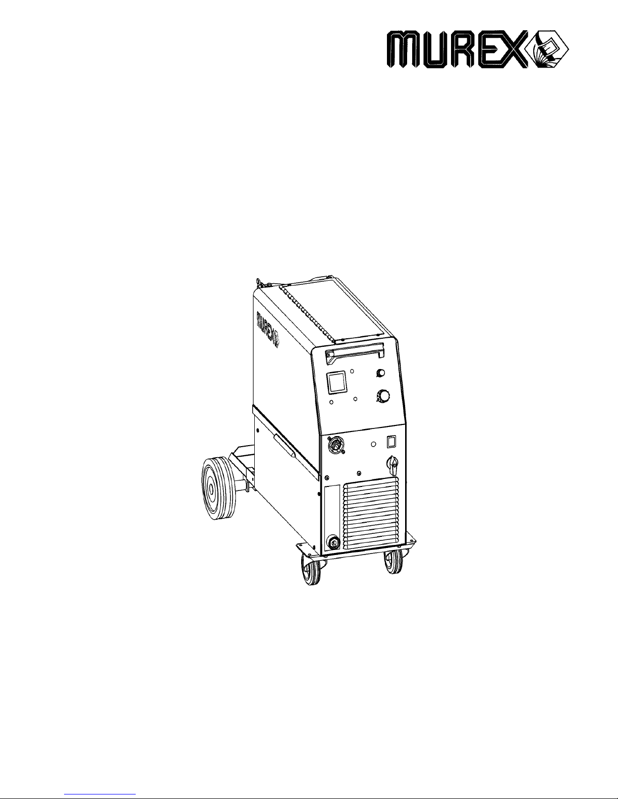
Murex Tradesmig 171 User manual

Valid for serial no. 8110349 301 146 080722
Tradesmig 171/201
Tradesmig 251
Instruction manual

-- 2 --
declaration
DECLARATION OF CONFORMITY
Murex Welding Products Ltd.
Declare hereby that:
Murex Tradesmig 171 201 251
Part No. 0349 311 660,0349 311 650, 0349 311 640
Manufactured after 1st May 2005
Sconform with the requirements of Council Directive 72/23/EEC, amended by
Council Directive 93/68/EEC, relating to electrical equipment designed for use
within certain voltage limits.
Sconform with the requirements of Council Directive 89/336/EEC, amended by
Council Directive 93/68/EEC, relating to electromagnetic compatibility.
Sare manufactured in accordance with EN60974-1 Safety Requirements for Arc
Welding Equipment.
Sare manufactured in accordance with EN60974-10 Electromagnetic Compatibility
for Arc Welding Equipment.
On behalf of oMurex Welding Products Ltd.
H
a
n
o
v
e
r
H
o
u
s
e
,
Q
u
e
e
n
s
g
a
t
e
H
a
n
o
v
e
r
H
o
u
s
e
,
Q
u
e
e
n
s
g
a
t
e
Britannia Road, Waltham Cross
Herts. EN8 7TF
England
Kent Eimbrodt
Global Director
Equipment and Automation
Manufactured by E ab Welding Equipment AB.

ENGLISH
-- 3 --
TOCe
1 SAFETY 4...........................................................
2 INTRODUCTION 6...................................................
2.1 Equipment 6................................................................
3 TECHNICALDATA 6.................................................
4 INSTALLATION 8....................................................
4.1 Placing 8...................................................................
4.2 A emblyofcomponent 8...................................................
4.3 Electricalin tallation 9.......................................................
4.4 Main power upply 9........................................................
5 OPERATION 10.......................................................
5.1 Connectionandcontroldevice 10.............................................
5.2 Function explanation 11......................................................
6 MAINTENANCE 11....................................................
6.1 In pectionandcleaning 11....................................................
7 FAULTTRACING 12...................................................
DIAGRAM 13............................................................
WEARCOMPONENTS 20.................................................
ACCESSORIES 21.......................................................
Right re erved to alter pecification without notice.

-- 4 --
T1725e
1 SAFETY
U er of welding equipment have the ultimate re pon ibility for en uring that anyone who work on
or near the equipment ob erve all the relevant afety precaution . Safety precaution mu t meet
the requirement that apply to thi type of welding equipment. The following recommendation
hould be ob erved in addition to the tandard regulation that apply to the workplace.
All work mu t be carried out by trained per onnel well--acquainted with the operation of the welding
equipment. Incorrect operation of the equipment may lead to hazardou ituation which can re ult
in injury to the operator and damage to the equipment.
1. Anyone who u e the welding equipment mu t be familiar with:
Sit operation
Slocation of emergency top
Sit function
Srelevant afety precaution
Swelding
2. The operator mu t en ure that:
Sno unauthori ed per on i tationed within the working area of the equipment when it i
tarted up.
Sno--one i unprotected when the arc i truck
3. The workplace mu t:
Sbe uitable for the purpo e
Sbe free from draught
4. Per onal afety equipment
SAlway wear recommended per onal afety equipment, uch a afety gla e , flame--proof
clothing, afety glove .
SDo not wear loo e--fitting item , uch a carve , bracelet , ring , etc., which could become
trapped or cau e burn .
5. General precaution
SMake ure the return cable i connected ecurely.
SWork on high voltage equipment may only be carried out by a qualified electrician.
SAppropriate fire extinqui hing equipment mu t be clearly marked and clo e at hand.
SLubrication and maintenance mu t not be carried out on the equipment during operation.

-- 5 --
T1725e
WARNING
READ AND UNDERSTAND THE INSTRUCTION MANUAL BEFORE INSTALLING OR OPERATING.
ARC WELDING AND CUTTING CAN BE INJURIOUS TO YOURSELF AND OTHERS. TAKE PRECAU-
TIONS WHEN WELDING. ASK FOR YOUR EMPLOYER’S SAFETY PRACTICES WHICH SHOULD BE
BASED ON MANUFACTURERS’ HAZARD DATA.
ELECTRIC SHOCK -- Can kill
SIn tall and earth the welding unit in accordance with applicable tandard .
SDo not touch live electrical part or electrode with bare kin, wet glove or wet clothing.
SIn ulate your elf from earth and the workpiece.
SEn ure your working tance i afe.
FUMES AND GASES -- Can be dangerous to health
SKeep your head out of the fume .
SU e ventilation, extraction at the arc, or both, to take fume and ga e away from your breathing zone
and the general area.
ARC RAYS -- Can injure eyes and burn skin.
SProtect your eye and body. U e the correct welding creen and filter len and wear protective
clothing.
SProtect by tander with uitable creen or curtain .
FIRE HAZARD
SSpark ( patter) can cau e fire. Make ure therefore that there are no inflammable material nearby.
NOISE -- Excessive noise can damage hearing
SProtect your ear . U e earmuff or other hearing protection.
SWarn by tander of the ri k.
MALFUNCTION -- Call for expert assistance in the event of malfunction.
PROTECT YOURSELF AND OTHERS!
WARNING!
Read and under tand the in truction manual
before in talling or operating.
Do not u e the power ource for thawing frozen pipe .
WARNING!
This product is solely intended for arc welding.
Do not dispose of electrical equipment together with normal waste!
In ob ervance of European Directive 2002/96/EC on Wa te Electrical and Electronic
Equipment and it implementation in accordance with national law, electrical equipment
that ha reached the end of it life mu t be collected eparately and returned to an
environmentally compatible recycling facility. A the owner of the equipment, you hould
get information on approved collection y tem from our local repre entative.
By applying thi European Directive you will improve the environment and human health!

-- 6 --
T1725e
2 INTRODUCTION
Tradesmig 171 201 251 are tep controlled power ource in a compact de ign, intended for welding
with olid teel, tainle teel or aluminium wire a well a tubular wire with or without hielding ga .
2.1 Equipment
The power ource i upplied with:
SReturn cable 3m with return clamp
SShelf for ga cylinder
SIn truction manual
3 TECHNICAL DATA
Tradesmig 171
Voltage 230--240V, 1∼50 60Hz
Permissible load at
100% duty cycle 76A/17,8V
60 % duty cycle 98A/18,9V
25 % duty cycle 155A/21,7V
20 % duty cycle 170A/21,0V
Setting range (DC) 30A/15,5V--155A/21,7V (170A/21,0)
Open circuit voltage 22,4--44,5V
Open circuit power 270W
Power factor at max load 0,91
Control voltage 42V, 50/60Hz
Wire feed speed 1,0--17m/min
Burnback time 0,02--0,25
Spot welding 0,2--2,5
Welding gun connection EURO
Wire dimension range 0,6--0,8(Fe)
1,0(Al)
0,8(cored)
0,8--1,0(CuSi)
Max diameter weight
of wire bobin
300mm/15kg
Dimensions lxwxh 860x420x730
Weight 62kg
Operating temperature --10 ÷+40oC
Enclosure class IP 23
Application classifica-
tion

-- 7 --
T1725e
Tradesmig 201 Tradesmig 251
Voltage 230--240V, 1∼50 60Hz 230--240V, 1∼50 60Hz
Permissible load at
100% duty cycle 90A/18,5V 110A/19,5V
60 % duty cycle 115A/19,7V 140A/21,0V
@ % duty cycle 185A/23,3V @ 23% 200A/24,0V @ 30%
20 % duty cycle 200A/23,0V 250A/21,0V
Setting range (DC) 30A/15,5V--185A/23,3V
(200A/23,0V)
40A/16,0V--200A/24,0V
(250A/21,0V)
Open circuit voltage 19,6--44,9V 19,0--41,5V
Open circuit power 120W 200W
Power factor at max load 0,89 0,92
Control voltage 42V, 50/60Hz 42V, 50/60Hz
Wire feed speed 1,0--17m/min 1,9--19m/min
Burnback time 0,02--0,25 0--0,25
Spot welding 0,2--2,5 0,2--2,5
Welding gun connection EURO EURO
Wire dimension range 0,6--1,0(Fe)
1,0(Al)
0,8--1,0(cored)
0,8--1,0(CuSi)
0,6--1,2(Fe)
1,0--1,2(Al)
0,8--1,2(cored)
0,8--1,0(CuSi)
Max diameter weight
of wire bobin
300mm/15kg 300mm/15kg
Dimensions lxwxh 860x420x730 860x420x730
Weight 70kg 92kg
Operating temperature --10 ÷+40oC --10 ÷+40oC
Enclosure class IP 23 IP 23
Application classifica-
tion
Duty cycle
The duty cycle refer to the time a a percentage of a ten--minute period that you can weld at a cer-
tain load without overloading.
Enclosure class
The IP code indicate the enclo ure cla , i. e. the degree of protection again t penetration by olid
object or water. Equipment marked IP23 i de igned for indoor and outdoor u e.
Application class
The ymbol indicate that the power ource i de igned for u e in area with increa ed
electrical hazard.

-- 8 --
T1725e
4 INSTALLATION
The installation must be executed by a professional.
WARNING!
Thi product i intended for indu trial u e. In a dome tic environment thi product may cau e radio
interference. It i the u er’ re pon ibility to take adequate precaution .
4.1 Placing
Po ition the welding power ource uch way that it cooling air inlet and outlet are
not ob tructed.
4.2 Assembly of components
For packing and hipment of the machine the wheel are detached from the unit.
Before u e attach the wheel according to in truction.
WARNING!
1.
3.
2.
M8x16
M6x16

-- 9 --
T1725e
4.3 Electrical installation
4.4 Mains power supply
Check that the unit i connected to the correct main power upply voltage, and that it i protected by
the correct fu e ize. A protective earth connection mu t be made, in accordance with regulation .
Rating plate with supply connection data
Tradesmig 171 Tradesmig 201 Tradesmig 251
Voltage V 220--230V,
1∼50/60Hz
220--230V,
1∼50/60Hz
220--230V,
1∼50/60Hz
Current A
at 100% duty cycle 12,0 13,0 16,6
at 60% duty cycle 15,7 18,2 23,4
at @% duty cycle 27,8 @ 25% 36,2 @ 23% 38,7 @ 30%
at 20% duty cycle 29,7 39,0 47,5
Cable area mm2
22
23 x 1.5 3 x 2.5 3 x 4,0
Fuse low A16 20 35

-- 10 --
T1725e
5 OPERATION
General safety regulations for the handling of the equipment can be found on
page 4. ead through before you start using the equipment!
WARNING!
Rotating part can cau e injury, take great care.
WARNING -- TIPPING RISK!
There i a ri k of tipping while tran portation and operation, if the welding machine lean
more than 10o. In that ca e appropriate ecuring ha to be provided !
5.1 Connection and control devices
1Main upply witch with indicating lamp 6Knob for pot welding -- ON/OFF and time
etting
2Orange indicating lamp, overheating 7Knob for wire peed etting
3Welding voltage witch
T171: 8 tep
T201: 12 tep
T251: 12 tep
8Digital in trument -- V/A,
(option, ee page 21)
4EURO -- connector for welding gun 9Knob for burn--back time etting.
In T251 located in wire feeder compartment,
in T171/T201 located on control board.
5Connection for return cable (--)

-- 11 --
T1725e
5.2 Functions explanation
5.2.1 Overheating protection
When the machine i witched on with the main witch [1], indicating lamp [1] i on and
lamp [2] off -- the machine i ready to operate. If the internal temperature become too
high, the welding i interrupted and di abled. Thi tate i indicated by lighting of the
orange indicating lamp [2] on the front of the machine. It re et automatically when the
temperature ha fallen.
6 MAINTENANCE
Regular maintenance is important for safe, reliable operation.
Note!
All guarantee undertakings from the supplier cease to apply if the customer himself
attempts any work in the product during the guarantee period in order to rectify any
faults.
6.1 Inspection and cleaning
Check regularly that the power ource i free from dirt.
The power ource hould be regularly blown clean u ing dry compre ed air at reduced
pre ure. More frequently in dirty environment . Otherwi e the air inlet/outlet may be-
come blocked and cau e overheating.
Welding gun
SCleaning and replacement of the welding gun’ wear part hould take place at
regular interval in order to achieve trouble--free wire feed. Blow the wire guide
clean regularly and clean the contact tip.
The brake hub
The hub i adju ted when delivered, if
readju tment i required, follow the in truction
below. Adju t the brake hub o that wire i lightly
lack when wire feed top .
SAdjusting the braking torque:
STurn the red handle to the locked po ition.
SIn ert a crewdriver into the pring in the hub.
Turn the pring clockwi e to reduce the braking torque
Turn the pring anticlockwi e to increa e the braking torque. NB: Turn both
pring through the ame amount.

-- 12 --
T1725e
7 FAULT TRACING
Try these recommended checks and inspections before sending for an authorised service technican.
Type of fault Actions
No arc SCheck that the main power upply witch i turned on.
SCheck that the welding current upply and return cable are
correctly connected.
SCheck that correct current value i et.
Welding current i interrupted
during welding
SCheck whether the thermal overload trip ha operated
(indicated by the orange lamp on the front).
SCheck the main power upply fu e .
Thermal overload trip
operate frequently
SCheck to ee whether the air inlet /outlet are clogged.
SMake ure that you are not exceeding the rated data for the
power ource (i.e. that the unit i not being overloaded).
Poor welding performance SCheck that the welding current upply and return cable are
correctly connected.
SCheck that the correct current value i et.
SCheck that the correct welding wire are being u ed.
SCheck the main power upply fu e .
SCheck the wire feed unit -- if proper roll are applied and
properly et the pre ure of the wire feeder’ pre ure roller
Tradesmig 171 201 251 is designed and tested in accordance with the international and
European standards IEC EN 60974--1 and EN 60974--10. It is the obligation of the servi-
ce unit which has carried out the service or repair work to make sure that the product
still conforms to the said standard.

Diagram
-- 13 --
dT1725
Tradesmig 171, 240V (valid untill June 2008)

-- 14 --
dT1725
Tradesmig 171, 240V (valid from July 2008)

-- 15 --
dT1725
Tradesmig 201, 240V (valid untill June 2008)

-- 16 --
dT1725
Tradesmig 201, 240V (valid from July 2008)

-- 17 --
dT1725
Tradesmig 251, 240V (valid untill June 2008)

-- 18 --
dT1725
Tradesmig 251, 240V (valid from July 2008)

Tradesmig 171/201/251
Edition 080722
-- 19 --
oT1725
Valid for serial no. 811--XXX--XXXX
Ordering numbers
0349 311 660 Trade mig 171 240V 1∼
∼∼
∼50/60Hz
0349 311 650 Trade mig 201 240V 1∼
∼∼
∼50/60Hz
0349 311 640 Trade mig 251 240V 1∼
∼∼
∼50/60Hz

Tradesmig 171/201/251
Edition080722
-- 20 --
wT1725
Wear components
(W. F. Mechanism 0455 890 890 0455 890 882)
Item Denomination Ordering no. Notes
APre ure roller 0455 907 001
BFeed roller
0367 556 001
0367 556 002
0367 556 003
0367 556 004
Ø 0.6--0.8mm Fe, S , cored wire.
Ø 0.8--1.0mm Fe, S , cored wire.
Ø 1.0--1.2mm Fe, S , cored wire.
Ø 1.0--1.2mm Al wire.
CInlet nozzle 0466 074 001
DIn ert tube
0455 894 001
0455 889 001
Pla tic, mu t be u ed together with item 0455 885 001,
for welding with Al wire.
Steel, mu t be u ed together with item 0455 886 001.
EOutlet nozzle
0455 885 001
0455 886 001
Mu t be u ed together with item 0455 894 001,
for welding with Al wire.
Mu t be u ed together with item 0455 889 001.
The roller are marked with wire dimen ion in mm, ome are al o marked with inch.
Welding with aluminium wires.
In order to weld with aluminium wire , proper roller , nozzle and liner for
aluminium wire MUST be u ed. It i recommended to u e 3m long welding gun for
aluminium wire , equipped with appropriate wear part .
This manual suits for next models
3
Table of contents
Other Murex Welding System manuals

Murex
Murex Transarc DC303iE User manual

Murex
Murex Transmatic 4C Guide

Murex
Murex Transarc 250 Guide

Murex
Murex Transmatic AVC User manual

Murex
Murex Transtig AC/DC 205 User manual

Murex
Murex Tradesmig 283 User manual

Murex
Murex Tradestig 150 Guide

Murex
Murex Tradesmig 165 User manual

Murex
Murex Tradestig AC 220 Guide

Murex
Murex Tradestig 200-1 User manual