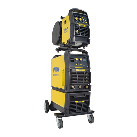
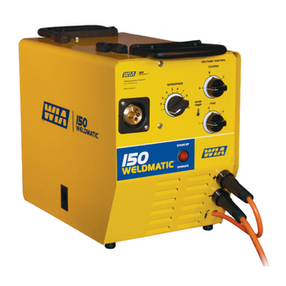
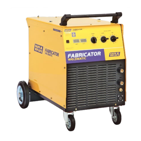
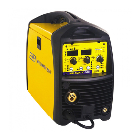
WIA WELDMATIC 335 User manual

WELDING INDUSTRIES
OF
AUSTRALIA
A
DIVISION
OF
WELDING INDUSTRIES
LTD
ABN
18
004
547
111
Head Officeand International
Sales
5
Allan Street, Melrose
Park
South Australia,
5039
Telephone
(08)
8276 6494 Facsimile
(08)
8276
6327
www.weldingindustries.corn.au
OWNERS MANUAL
WELDMATIC
335
MODELNO.
CP44-4,
REV.
B
1
l
/2000
QUALITY WELDINGPRODUCTS, SYSTEMSAND SERVICE
4
5
?/,!c
7
l
~~
-

Paae
2
WELDMATIC
335
MANUAL
-U-
The information contained
in
this manual is set out to enable you to properly
maintainyour new equipmentand ensure that
you
obtain maximum operatingefficiency
.
Pleaseensure that this informationis kept in asafe placefor ready referencewhen
requiredat any future time
.
When requesting spare parts. please quote the modeland serial numberof the
machine and part number of the item required
.
Ail
relevant numbers are shown
in
lists
contained
in
this manual
.
Failure to supply this information may result
in
unnecessary
delays
in
supplyingthe correct parts
.
SAFETY
Beforethis equipment is put into operation.the Safe Practices section at the back
of the manual must be read completely
.
This will help toavoid possible injury due to
misuse
or
improperwelding applications
.
CONTENTS
Sec
.
1
....................
Introduction
....................................................
P.3
..
Sec.2
....................
Recelvlng
.......................................................
P.3
Sec.3
....................
Speclflcatlons
.................................................
P.4
...
Sec.4
....................
Power SourceControls
..................................
P.5
Sec.5.
...................
Installation
......................................................
P.6
Sec.6
....................
Normal Welding Sequence
............................
P.9
Sec.7
....................
BasicWelding Information
.............................
P.9
Sec.8
....................
GeneralMaintenance
.....................................
P
.
12
Sec.9.
...................
Trouble Shooting
............................................
P
.
12
Sec
.
10
..................
Service Information
........................................
P
.
14
Sec
.
11
..................
PartsLists
......................................................
P
.
16
Sec 12
..................
Safe Practices
................................................
P
.
19
FIGURES
Fig
.
1
.....................
Power SourceControls
..................................
P.5
Fig.3
.....................
PositiveWire Connection
...............................
P.8
Fig.4
.....................
NegativeWire Connection
.............................
P.8
Fig.5
.....................
"Good" Weld
...................................................
P
.
11
Fig.8
.....................
Circuit Diagram CP44-4
.................................
P
.
14
Fig.9
.....................
WirefeedControl Board CP42-12
..................
P
.
15
Fig.10
...................
Power Source Assembly
................................
P
.
17
Fig
.
1 1
...................
Wire DriveAssembly
......................................
P
.
18
Fig.2
.....................
Connectionof Supply Cable
...........................
P.6
Fig.6
.....................
"Bad" Weld
.....................................................
P
.
11
Fig.7
.....................
Gun Posltlon
...................................................
P
.
11
..

WELDMATIC
335
MANUAL
Page
3
1.
INTRODUCTION
Gas Metal Arc Welding (G.M.A.W.) is a basically simple welding process, where a
consumablewire is fed by motor driven drive rollers to a welding gun,andwhere welding
currentis supplied from the welding power source. The welding arc is struck between
the work piece and the end of the wire, which melts into the weld pool. The arc and the
weld pool are both shieldedbygasflowfrom thegun,
or
in the case of "selfshielded"
wires, bygases generated by the wire core.
The process is veryversatile in thatbyselectionof the correct wire composition,
diameter and shielding gas,itcan be used for applications ranging from sheetmetal to
heavyplate, and metals ranging from carbon steel to aluminium alloys.
The WELDMATIC 335 has been designed to beusedwith consumablewires in the
rangefrom 0.6mm to 1.6mmdiameter. The smaller wire sizesare used whenwelding at
lowercurrents,suchassheet-metalapplications.Increasing the wire diameter permits
higher welding currentsto beselected.
A common application
of
G.M.A.W.is for welding Mild Steel.
In
this application, a
Mild Steel solid consumable suchasAUSTMIGES6is used witha shielding gas of
Carbon Dioxide,
or
Argon mixed with Carbon Dioxide.Alternatively, Flux-cored
consumablesare available
in
both gas shielded, and 'gasless' selfshieldingtypes.
Stainless steel andAluminiumcan be welded withG.M.A.W. using the correct
consumablewire and shielding gas.
2.
RECEIVING
Check the equipment receivedagainsttheshippinginvoice to make sure the
shipmentiscomplete and undamaged.
If
anydamagehasoccurred in transit, please
immediately notify your supplier.
The CP44-4 packagecontains;
WELDMATIC335 Power source. (with meters
&
Internalwirefeeder)
BEXT2-4E3lOAEBERNARD Gun cable,
3
metre, Euro connector.
WGAC24 Regulator and Flowgauge. (Argon)
(This) OwnersManual.
l

Page
4
WELDMATIC
335
MANUAL
-
3.
SPECIFICATIONS
ManufacturedtoAustralian standard AS1966.1-1 985
PRIMARY 415 Vac,3 Phase 400 Vac.3 phase 380 Vac, 3 Phase
VOLTAGE 50/60
Hz.
50160
Hz.
50/60
Hz.
EFFECTIVE 14Amps
PRI. CURRENT 14Amps
14
Amps
l
MAXIMUM 22 Amps, 16kVA 20Amps, 14 kVA19Amps, 13 kVA
l
PR]. CURRENT
OPEN CIRCUIT 18to 44 Volts 17to 43 Volts 16to41 Volts
VOLTAGE in30 steps. in 30steps. in 30steps.
WELDING 35
-
335AMPS 35
-
335AMPS
35
-
320 AMPS
CURRENT RANGE
RATEDOUTPUT 190Amps, 190Amps,190Amps,
@g
25Volts,
@
24
Volts,
@
24 Volts,
100
%
DutyCycle 100
%
DutyCycle 100
%
Duty Cycle
260 Amps, 260Amps, 260 Amps,
@
30Volts,
@
26.5 Volts,
@
26.5 Volts,
55%
Dutycycle
55%
Dutycycle
55%
Dutycycle
335Amps, 335 Amps, 320 Amps,
32% Duty cycle 32
%
DutyCycle 35% Dutycycle
@
34Volts,
@
31Volts,
@
30 Volts,
CIRCUITBREAKER RATING
......
20 Amps
FITTEDSUPPLYCABLE
.............
47/0.20 Four Core, Heavy Duty PVC
WIRE SIZE
RANGE
.....................
0.6mm
-
l
.6mm diameter
COOLING
....................................
Fan cooled,air drawn inthroughtop louvre.
INSULATION
...............................
Class
H,
140°C Rise.
DIMENSIONS
..............................
L
-
870mm,
W
-
490mm,
H
-
73Qrnm
MASS..
.......................................
..l
1
3kg
Duty cycle is defined in Australian Standard AS1966.1as the ratio of arcing time to
5
minutesin any
5
minute period, expressedas a percentage.
,

WELDMATIC
335
MANUAL
Page
5
-
4.
P
TIZEMERVA!
(
COARSEVOLTAGESWITCH
FINEVOLTAGESWITCH
POWERONINDICATORLIGHT
INTERVALCONTROL
SPOTTIMECONTROL
WIRESPEEDCONTROL
VOLTMETER
AMMETER
PRE&POSTGASCONTROLS
(INTERNALADJUSTMENTS)
FIGURE
1.
POWER SOURCE CONTROLS
l.
POWER ON INDICATOR
power is connected to thewelder, andthe Coarse Voltageswitch is
in
positions 1,2or
3.
2.
COARSEVOLTAGE CONTROL
ranges, plus a
'0'
power
off
position.
3.
VOLTAGECONTROL
This is illuminated when the machine is energised, that is when electrical mains
This switch provides Coarse adjustment of the Output Welding Voltage over three
This switch providesten steps of Fineadjustmentof the OutputWelding voltage.
The wirefeed speed of the machine is varied with this control; turning the dial
in
a
4.
WIRE SPEED CONTROL
clockwisedirection increasesthe wirefeed speed, increasingthe welding current.
5. SPOTTIME CONTROL
When operatingthe machine
in
Spot Weld mode,this controlwill vary the spot weld
time. Rotatingthe dial clockwisewill increasethe spot weld time,
in
the range
0.5
-
2.5
seconds. If the Spot Weld mode is not requiredthis feature can beturned
off
by rotating
the controlanti-clockwiseuntil it 'clicks' intothe minimum position.
6.
INTERVAL CONTROL
When operating the machine
in
Cycle Arcmode this control sets the period
between welds. The spot time control sets the welding period. Rotating tne dial
clockwisewill increasethe intervaltime,
in
the range
0.5
-
2.5 seconds.
If
the CycleArc
mode is not required this feature can be turned
off
by rotating both controls fully anti-
clockwise.
7.
AMMETER
0
-
400A
8.
VOLTMETER
0
-
GOVDC
9.
PREAND POSTGAS CONTROLS
CP42-12 Wirefeed control board.Referto Figure
9
for adjustmentdetails.
Adjustabletimersfor preweld and postweld shjeldinggas flow are available on the

Paae
6
WELDMATIC
335
MANUAL
v
5.
INSTALLATION
CONNECTION
TO
ELECTRICALMAINS POWER SUPPLY
I
NOTE.All electical workshall only be undertaken
by
a
qualifiedelectrician.
I
1
I
The WELDMATIC 335 is supplied with a
5
metre
4
core
47/0.20
Heavy Duty
PVC
mains power supplycable. This cableshould be correctly connected to a suitable 3
Phase
plug
fop
or
fixed connectionpoint.
The minimum capacity
of
the mains wiring and power outlet supplying a welder
is
selected accordingto the
effectiveprimary current
of
the machine. The effective primary
currentfor a Weldmatic 335 is
14
Amps.
The minimum recommended circuit breaker ratingfor a Weldmatic 335 is 20Amps.
Note
:
The tripping time of a typical 20A circuit breaker may limitthe duty cycle available
from the Weldmatic 335. A higher rated circuit breaker can be selected, but the mains
wiring capacity must be increasedto suit.
The current rating of the mainscabledepends on cable size and method
of
installation. Refer to
AS/NZS
3008.1,
Table
9.
If it becomesnecessary
to
replace the
mains flexiblesupply cable,use only cablewith correct current rating.
Access to the machine supply terminalsis gained byremoving the power-source
side pane!oppositeto thewire-spool enclosure.
Pass the cable through the bush fitted tothe machineback panel. Thethree
phasesareterminatedatterminal block as shownin Figure2.
Tightenthe cableclamp leaving just sufficient slack in the cable such thatthe
terminatedwires are notintension.
~
MAINS
SUPPLY
CONNECTIONS
FIGURE
2.
CONNECTION
OF
SUPPLY
FLEXIBLE CABLE

~
WELDMATIC
335
MANUAL
Paae
7
-
-cl
FITTINGTHE GUN CABLE
The BERNARDBEQA31OAEguncable is equippedwitha 'Euro8wirefeeder
connector which incorporates all required connection pointsto the gun cable for welding
current, shieldinggas and gun switch control.
To attach the guncable
to
the wirefeeding mechanism, engagethe mating
parts
of
the male and female Euroconnectors,thenrotate the lockingring clockwise to firmly
secure the connection.
FITTINGTHE GAS BOTTLE
Dependingon configuration of the cylinderto be used,the gas flowmeter
/
regulator
may be fitted directly to the cylinder, or in conjunctionwithan elbow fitting.
DO
NOT
apply any greaseto thesejoints, and tightenthe nuts securely.
Fit the end of the gasinlet hose from the backpanel of the machineto the
connector supplied with the flow regulator, and secure withthe clampalso supplied.
FITTINGTHE CONSUMABLE WIRE
The quality of the consumable wiregreatlyaffectshowreliablya gas metal arc
welder will operate. Forbest results when welding mild steel, werecommendquality WIA
AUSTMIG ES6. Dirty, rusty
or
kinked wire will not feed smoothly through the gun cable
and will cause erratic welding.Deposits from thewire will clog the gun cable liner
requiring
it
to be replacedprematurely.
Placethe
spool
of welding wire ontothe spool holder. The location pin should mate
withaholeprovidedon the wirespoolbody.Fitthe spool retaining'R' clip supplied.
Check the adjustment
of
the spool brake, which should be set to prevent over-run of the
wire spool at the end of a weld, without unduly loading the wirefeed motor. The braking
can be adjusted bythe Nyloc nut using a 15/16"
AF
or 24mm socket wrench.
SELECTION
OF
START MODE
The
WELDMATIC
335
offers selection between 'Creep' and 'Standard' arc starting
modes. In creep mode,the electrode wireisfed at a reduced speedwhen thegun-switch
is
first closed. Once the arc is initiated, the wire accelerates to full welding speed. This
mode producesasofterarcstartwhich is recommended for aluminium welding
applications. If a faster arc startis required, standard modeshould be selected.
The selector switch is located on the wirefeed control board CP42-12 as shown in
Figure 11.Slide the switch upwards to select'Creep' mode, and downwards to select
'Standard' mode.
FEEDINGTHE CONSUMABLE WIRE
I
WIRE INCH
Withreference to Figure14,release the pressurescrew (IO), and rotate the
pressure arm
(8)
to the open position. The end of the welding wire can now be passed
through the inlet guide, over the bottom driven roller, andintothe output wire guide tube.
Check that the drive roller groove
is
correct for the wire in use. The appropriate size is
stamped onthe visible side of the installed roller. Check also thatthe correct size contact
tip is fitted at the gun end. Drive roller and tip details are available in Section
11
of this
manual.
Return the pressure arm to the closed position and, adjust the compressionscrew
to provide sufficient clamping of the drive rolls driveto achieve constantwirefeed. Do not
over tighten.
Withthe machine energised,close the gun switch to feedwire through the gun
cable.
If
creep speed
is
selected the wire will be initially fed at reduced speed, however
after a
short
timed periodthe ratewill increaseto
full
welding speed.
Page
8
WELDMATIC
335
MANUAL
OUTPUTVOLTAGE POLARITY.
The design of the WELDMATIC
335
allows selectionof the output voltagepolarity.
Most G.M.A.W. is carried out with thework piece Negativeand the welding
To
set the machinefor this condition, bolt the
'WORK'
lead onto the
(-)
output stud,
POSITIVE
WIRE
consumablewire Positive.
and the 'GUNCABLE' leadto the
(+)
stud, as in Figure
3.
below.
NEGATIVEWIRE
Some 'self-shielded'
flux
cored consumablesare intended to be operated with the
work piece Positive and the consumablewire Negative. Refer to the manufacturersdata
for the particular consumable
to
beused.
To
set the machinefor this condition, bolt the 'WQRK' leadonto the
(+)
output stud,
and the 'GUNCABLE' ontothe
(-)
stud,
as
in Figure
4.
below.
WORK
LEAD
Ti
GUEU'
J+
CABiE LEAD
FIGURE
3.
POSITIVE WIRE
l
~
GUN
CABLELEAD
WORK
LEAD
FIGURE
4.
NEGATIVEWIRE

WELDMATIC
335
MANUAL
Page
9
-
6.
NORMAL WELDING SEQUENCE
WELD
START
Closingthe weldinggun switch initiates thissequenceof events:
w
The gas valve is energised, gas flow commencesand continues for any pre-gas
time set;
The powersource contactor is initiated. Welding voltage isapplied betweenthe
work piece and the consumablewire.
Thewire drive motor is energised. If creep startmodeis selected,wirefeed
commencesat reducedspeed.
Thewire touchesthe work piece, and the arcis established. Ifcreep start mode is
selected, wirefeedrate increasesto full welding speed.
WELD END
Releasingthe gun switch initiates this sequence of events:
Thewire drive motor is de-energised, andis dynamically brakedto a stop;
After a short pre-set period, known as the 'burn-back' time, thePower-source
contactor functionis released. Thisperiodensures thatthe consumablewire does
not 'freeze' inthe weld pool. To adjust the 'burn-back' time, referto Figure
9.
At the completion of any post-gas time set, the gas valve is de-energisedand the
flow of shielding gas ceases.
To
adjust the preand post gas times,refer to Figure
9.
7.
BASIC WELDING INFORMATION
CHOICE
OF
SHIELDING GAS
The choice of shieldinggasislargelydeterminedbythe consumable wire tobe
used. Many proprietary shieldinggas mixturesare available.
The recommendedshielding gasesfor usewith the WELDMATIC
335
are
:
Mild Steel
................................
Argon
+
5
to
25%
CarbonDioxide;
Aluminium
...............................
Argon;
Stainless Steel
........................
Argon
+
1
to
2%
Oxygen.
Consult your gas supplierif morespecific information is required.
l

Page
10
WELDMATIC
335
MANUAL
1
SHIELDING
GAS
FLOW
RATE
In
G.M.A.
welding, one of the functions of the shielding gas is to protect the molten
weld pool from the effects of oxygen in the atmosphere. Without this protectionthe weld
deposit becomes 'honeycombed' in appearance,aneffectwhich is describedas weld
porosity.
In draft-free conditionsthe gas flow rate required to give adequate protection
is
typically
10
litres/min. In situations where drafts cannot be avoided, it may be necessary
to
increasethis rate and/or to provide screening of thework area.
Weld porosity canalso be caused byairenteringthegasstream through a
damaged hose, loose gasconnection, or fromrestriction in thenozzle,suchas from
excess build-up of spatter.
Particularly when welding aluminium, porosity can occur at the start and end of a
weld.
For
this reason itis recommendedthat some pre and post gas flow time be set.
This ensures that the welding zone is protectedfrom atmospheric contamination before
the arc is established, and as the weld pool solidifies atthe end ofaweld. Refer to
Figure
11
for adjustment details.
ESTABLISHING
A
WELD
SETTING
two variables that are adjusted in order to obtain a stablearc are;
Oncethe consumablewire type, wire size and shielding gashavebeen chosen, the
Wirefeed speed,
Weldingarc voltage.
The wirefeed rate determinestheweldingcurrent;increasingthe feed rate
increases the current, and decreasing it decreasescurrent. The selected wirefeed rate
must bematched with sufficient arc voltage;anincrease
of
wirefeed rate requires an
increase
of
arc voltage.
If
the voltage is too low the wire will stub and stutter, and there will not be a steady
arc. If the voltage is too high the arc will be longwiththe metal transfer within the arc
occurring as aseries of large droplets.
The welding currentshould be chosen to suitthethicknessof the metal to be
welded. It is important to check that the depositedweldprovidessufficient strength to
suit the application.

WELDMATIC
335
MANUAL
Page
ll
A
"good"weld will have the characteristicsillustrated in Figure
5.
The weld has
penetrated into the parent metal, fusing the root
of
the joint where the two plates meet,
andthe weld blends smoothlyintothe side walls.
A
"bad" weld is shown in Figure
6.
The weld has not penetratedthe joint root, and
there is poor side wall fusion. Thislack of fusion would normally be corrected by
increasingthe arc voltage, or by increasing bothwirefeed rate and arc voltageto achieve
a higher current weld setting.
L
L
FIGURE
5.
"GOOD"WELD FIGURE
6.
"BAD" WELD
GUN
POSITION
belowwith the nozzle end pointing inthe direction
of
travel.
For "down hand" fillet welding, the gun is normallypositionedas shown in Figure
7
1
d
F
.S',
l
FIGURE
7.
GUN POSITION

Page
l2
WELDMATIC
335
MANUAL
-
8.
GENERAL MAINTENANCE
DUST
Careshould
be
takentopreventexcessive build-up
of
dustand dirtwithin the
weldingpowersource. It
is
recommendedthatatregularintervals,accordingtothe
prevailingconditions,themachinecovers
be
removedandanyaccumulateddust
be
removed by the use
of
dry,
low
pressure compressed air, or
a
vacuum cleaner.
WIREFEED
In order to obtain the most satisfactory welding results from
the
G.M.A.W.
process,
thewirefeedmust
be
smoothandconstant. It
is
thereforeimportantto
observe
the
following points;
Keep the gun
cable
liner clear
of
dust
and
swarf build-up. When replacement
becomes necessary,fit only the correct
liner
to suit the gun
cable
model.
See
Section
11.
The
build-up
of
dust in
a
cable
liner can
be
minimised by regular
purging
of
the liner with dry compressed air.
This
may
be
conveniently done
each
time the wire spool
is
replaced.
Replace the weldingtip
as
it becomes worn.
H
Keep the wire drive mechanism clean. Periodically check the drive rollers for wear
and
for
free rotation.
Check that the consumable wire spool holder rotates smoothly and that the
braking action
is
not excessive.
This
also
may
be
conveniently done
each
time the
wire
is
replenished.
l

l
1
l
l
WELDMATIC
335
MANUAL
Paae
13
v
~~ ~ ~
9.
TROUBLE
SHOOTING
UNSATISFACTORY RESULTS
WIREFEED
Erraticwirefeed is theMOST LIKELY causeof failure in all Gas MetalArc
Welding. It should thereforebethe first point checkedwhen problems occur. Refer
to the section above.
Checkfor correct gas flowrate at the weldingtorch nozzle and ensure there are
no gas leaks.The gun nozzlemust befree from spatter andfirmly attached
to
the
welding gunto ensure that air is notdrawn into the shielded area.
Checkthat the shielding gas selected is correctfor the consumablewire in use.
WELDING CIRCUIT
Ensurethat the work clamp is securely tightened onto the work-piece
so
that
goodelectricalcontact is achieved. Check also thatthe output polarity selected is
appropriatefor the consumable
in
use.
Contaminationof the work-piece surface by water, oil, grease, galvanising, paint,
or oxide layers can severely disturb the welding arcand result in a poor weld. The
contaminating material shouldbe removedbefore welding.
WIREFEED
/
ARC VOLTAGE RELATIONSHIP
If the consumablewire is stubbing into the work piece,and a steady arc cannot be
obtained, it is likely that the arc voltage is set too low
to
suit the wire speed. To correct
this situation either increase arc voltage,or decrease the wire speed.
If the arc length is too long, the arc voltage
is
too
high
to
suit the wire speed.
To
correct this, increase wirespeedor decrease arc voltage.
NOWELDING CURRENT
that the fan is runningandthe indicator lightis illuminated.
Check that Mains SupplyisavailableattheWELDMATIC
335
Power Source, i.e.
Check continuity
of
the welding current circuit, i.e., work lead, work clamp and gun
cable connections.
The WELDMATIC
335
welding power sourceincorporates an in built over
temperature thermostatwhich will trip ifthewelding load exceeds the operating duty
cycle.
In this event the machine will notdeliverweldingcurrent until the machine has
cooled sufficiently. The thermostat will resetautomatically
-
donot switch the machine
off
as the coolingfan will assist theresetting
of
the thermostat.
Ifthe forgoing checks have been madeand have not revealedthe fault condition, a
QUALIFIEDSERVICE PERSON shouldbeconsulted.

Paae
24 WELDMATIC
335
MANUAL
v
~~~__
~ ~~ ~
IO.
SERVICE
INFORMATION.
E
U
+
220
LY
z
3
I
06
0
$?k
W
W
W
n:
P
UJ~
b
41
(I
1,
-
QJ
>
nn
5%
-
n
W
3
5
LY
v)
3
p
v)
0
a
E
5
03
H0
z
3
0
v.-
"
Ln
m-
a
W
0
0
0
w
-l
W
F
(r
5
I
0
Y
al
c
2
g
0
3
._
U
0
FIGURE
8.
CP44-4 CIRCUIT
DIAGRAM

WELDMATIC
335
MANUAL
Page
'l5
WIREFEED CONTROL
BOARD
CP42-l2
The wirefeed control boardprovidesthe followingfunctions:
Wirefeed motor on/off controlin responseto the gun-switch.
Speed control of the wirefeed motor.
Switchablecreepktandardwirefeed start modes.
Burn-back control.
Brakingof thewirefeed
motor
at end ofweld.
Spot-weldtimer.
Intervaltimer.
Preand Post gas controltimers.
Pullgun motor speedcalibration,(wherepullgun fitted).
Local
or
remote wire speed control.
Connections to theboard,and servicepoints are detailed
in
the drawing below.
The circuit isfactory calibratedfor a maximum push motordrive roller speed of
160
rpm.
rF=
PULL MOTOR+VE
7
REMOTESPEEDPOT.1K
PULL MOTOR-VE
REMOTESPEEDPOT.1K
PULL MOTOR FUSE
1.6ASTD.ACT.
INDUCTANCE START MODE
Wll
UP=CREEP START
DOWN=STANDARD
PRE-GAS-
TIMER
GUN
GUN
j:l@&
WITCH
_1
I
WITCH
P2
PUSH MOTOR-VE
'
I
PUSH MOTOR+VE
'CH
o
=SA STDACT
FUSE
01
PI
CONTACTORCONTROL
CONTACTORCONTROL
GAS
VALVE +VE
GASVALVE-VE
FIGURE
9.
WIREFEED CONTROLBOARD

Page
16
WELDMATIC
335
MANUAL
1
l.
PARTS
LISTS
WELDMATIC
335
POWER
SOURCE
ITEM
#
.............
PART
#
........................
DESCRIPTION
l
...........................
CP42-l2
..............................
Printed Circuit Board
1.1
........................
W11-7/16
............................
Relay,24v (2)
2
...........................
CP42-20
..............................
Front Panel
3
...........................
CP42-22
..............................
Back Panel
4
...........................
CP42-23
..............................
Centre Panel
Includes
5
...........................
CP44-23
..............................
Base Assembly
Includes
5.1
........................
CP42-24/6
...........................
Castor Wheel(2)
6
...........................
CP42-25
..............................
BafflePanel
7
...........................
CP42-26.
.............................
Side Cover, Fixed
8
...........................
CP42-27
..............................
Side Cover, Fixed, Lower
9
...........................
CP42-28
..............................
Side Cover, Opening
10
.........................
CP42-29
..............................
Top Cover
11
.........................
CP42-30
..............................
PCB Cover
12
.........................
CP42-31
..............................
RectifierMounting Bracket (2)
13
.........................
CP44-41
..............................
Welding Transformer Assembly
14
.........................
CP44-40
..............................
Inductance Assembly
15
.........................
CP42-0/1
.............................
RectifierAssembly
16
........................
.CP42-32
..............................
Output Terminal Insulating Support
17
.........................
CP42-33
..............................
Positive Busbar
18
.........................
CP42-34
..............................
Negative Busbar
19
.........................
CP42-39
..............................
Handle Assembly
20
.........................
W27-2
.................................
Motor and Two
Roll
Drive Assembly
21
.........................
TC396-1
..............................
Euro
Gun Adaptor
22
.........................
CP101-0/18
.........................
Gas Valve
23
.........................
W1
1-1
1/1
............................
Hose Barb
24
.........................
CP27-0/15
...........................
Fan
25
.........................
CP42-0/2
.............................
Control Transformer
26
.........................
W17-2/12
............................
Lens
27
.........................
CP27-0/18
...........................
Contactor
28
.........................
CP43-0/8.
............................
Coarse Voltage Switch
29
.........................
CP43-0/3
.............................
Fine Voltage Switch
30
.........................
W11-0/16
............................
Potentiometer Knob, Large
32
.........................
LG300
.................................
Work Clamp
33
.........................
CP34-02/8
...........................
Ammeter Shunt
34
.........................
CP33-0/10
...........................
Ammeter
0
-
400A
35
.........................
CP33-0/11
...........................
Voltmeter
0
-
6OVDC
31
.........................
W5-10/19
............................
Potentiometer Knob, Small (2)
37
.........................
AM1
77
................................
Spool Holder Assembly
Includes
37.1
......................
AM133-3
..............................
R
Clip
38
.........................
W11-13
...............................
InsulatingSpacer Bush(2)
40
.........................
CP42-0/3
.............................
Rubber Tyre Wheel(2)
43
.........................
HOS5R
...............................
Gas Hose
47
........................
.SGC030
..............................
Steel Chain 650mm
50
.........................
CP3-0/23
.............................
Rubber Grommet
54
.........................
MK6/3
.................................
Terminal Block(2)
39
.........................
MC1 1-32/2
..........................
Nylon InsulatingBush (2)
42
.........................
CAB4C47HD
.......................
Mains SupplyFlexibleCable

WELDMATIC
335
MANUAL
Page
l7
ww
Ecc
wu
FIGURE
IO.
WELDMATIC
335
POWER SOURCE ASSEMBLY

Page
18
WELDMATIC
335
MANUAL
-
W51-0. FOUR ROLL DRIVE ASSEMBLY
ITEM
#
PART
#
DESCRIPTION
1
..........
W51-0/11
......
Feed Plate
2
..........
W51-0/12
......
GearWheel
3
..........
W51-0/13
......
FixingCap
4
..........
W51-0/14
......
Screw M4x12
5
..........
W51-0/15
......
Woodruffs Key 3x6.5
6
..........
W36-0/17
......
Motor
&
Gearbox
7
..........
W51-0/17
......
Bronze Bearing(8)
8
..........
W51-0/18
......
GearWheel (2)
9
..........
W51-0/19
......
ParallelKey4x4.8 (2)
10
........
W51-0/2
........
Feed
Roll
0.9mm+l.2mm
“V”
1 1
........
W51 -0/20
......
FixingCap (2)
12
........
W51-0/21
......
Shaft (2)
13
........
W51-0/22
......
GearWheel Complete (2)
14
......
..W51 -0/23
......
Circlip(2)
15
........
W51-0/24
......
Shaft (2)
16
........
W51-0/25
......
PressureArm (2)
17
........
W51-0/26
......
Shaft (2)
18
........
W51-0/27
......
IntermediateGuide
1 9
........
W51 -0/28
......
FixingArm
20
........
W51 -0/29
......
CalibratedCollar
22
........
W51 -0/31
......
Cap
for
FixingShaft
21
........
W51-0/30
......
Pressure Spring
23
........
W51-0/32
......
Circlip(2)
24
........
W51-0/33
......
Inlet Guide
25
........
W51-0/34
......
Wire Guide Tube
26
........
W51-0/35
......
Motor
8,
Gearbox
27
........
W51-0/36
......
PressureArm Spring
28
........
W51-0/37
......
Circlip(2)
29
........
W51-0/38
......
Screw M6x16(3)
30
........
W51 -0/39
......
Circlip(3)
31
........
W51-0/4
O......
Screw M6x6(2)
ALTERNATIVE PARTS
(IO)
.....
W51-0/3
........
FeedRoll 0.9mm+l.2mm
“U”
(-IO)
.....
W51-0/1
........
Feed
Roll
1.2mm+l.6mm Knurled
(IO)
.....
W51-0/4
........
Feed
Roll
0.8mm+l.Omm
“V
(l
0)
.....
W51-0/5
........
Feed
Roll
0.6mm+0.8mm
“V
FIGURE 11. W51-0. FOUR ROLLDRIVEASSEMBLY

WELDMATIC
335
MANUAL
Page
l9
12.
SAFE PRACTICESWHEN USING WELDING EQUIPMENT
These notes are provided in the interests of improving operator safety. They should be considered
only asa basicguideto SafeWorking Habits.A full list
of
Standards pertainingto industry is availablefrom
the Standards Association of Australia,alsovarious State ElectricityAuthorities, Departments of Labour
and Industry orMinesDepartmentandotherLocal Health or Safety Inspection Authorities mayhave
additionalrequirements. WTlA TechnicalNoteTN7-98alsoprovides a comprehensiveguide to safe
practicesinwelding.
EYE PROTECTION
NEVER
LOOK
AT AN ARC WITHOUT PROTECTION. Wear a helmet with safety gogglesor
glasses with side shields underneath, with appropriatefilter lenses protected by clear cover Pens. This is a
MUSTfor welding, cutting, and chippingto protectthe eyes from radiant energy andflying metal. Replace
the cover lens when broken,pitted,or spattered.
Recommended shadefilter lens.
Amps
TIG
MMAW
MCG Pulsed
MIG
0-100
.............
10
.................
9
...................
10
.................
12-13
100-150
.........
11
.................
10
.................
10
.................
12-13
150-200
.........
12
.................
10-11
............
11-12
............
12-13
200-300
.........
13
.................
l1
.................
12-13
............
12-13
300400
.........
14
.................
12
.................
13
.................
14
400500
............................
"
13
.................
14
.................
14
500
+
...................................................
"
--
14
.................
14
BURN PROTECTION.
The welding arc is intense andvisiblybright. Its radiation can damageeyes, penetrate lightweight
clothing, reflect from light-colouredsurfaces, and burn the skin andeyes.Burns resulting from gas-
shieldedarcs resemble acute sunburn, but canbe more severe and painful.
Wear protectiveclothing
-
leatherorheatresistantgloves,hat,andsafety-toe boots. Button shirt
collar and pocket flaps, and wearcufflesstrousers
to
avoid entryof sparks and slag.
Avoid oily or greasy clothing.A spark may ignite them. Hotmetal such as electrode stubs and work
piecesshould never be handled without gloves.
Ear plugsshould be worn whenweldinginoverheadpositionsorin a confined space. A hard hat
should bewornwhen others are working overhead.
Flammablehair preparations should not be used by persons intendingto weld or cut.
TOXIC
FUMES.
Adequate ventilation withair is essential. Severe discomfort, illness or death can result from fumes,
vapours, heat,
or
oxygen depletionthat welding or cutting may produce. NEVER ventilatewith oxygen.
Lead, cadmium, zinc, mercury, and beryllium bearing and similar materials whenwelded
or
cut may
produce harmful concentrations of toxic fumes. Adequate local exhaust ventilation must be used, or each
person in the area as well as the operator must wear an air-supplied respirator. For beryllium, both must
be used.
Metals coatedwithorcontaining materialsthatemitfumes shouldnotbe heated unless coating is
removed from the work surface, the areaiswellventilated,or the operatorwearsanair-supplied
respirator.
Work in
a
confined space onlywhile
it
isbeingventilatedand, if necessary,whilewearingair-
supplied respirator.

Page
20
WELDMATIC
335
MANUAL
Vapours from chlorinatedsolventscanbedecomposed by theheat of the arc(orflame) to form
PHOSGENE, a highly toxic gas,andlungandeyeirritatingproducts.Theultra-violet(radiant)energy of
the arc can also decompose trichlorethylene and perchlorethylene vapoursto form phosgene.
Do
not weld
orcutwheresolvent vapourscanbedrawn intotheweldingor cutting atmosphereorwhere the radiant
energycanpenetrate to atmospherescontainingevenminuteamounts of trichlorethyleneor
percholorethylene.
FIRE AND EXPLQSIQN PREVENTION.
Be awarethat flying sparks
or
falling slag can pass through cracks, along pipes, through windows
or
doors, and through
wall
or
floor
openings, out
of
sight of the operator. Sparks and slag cantravel upto
10
metresfrom thearc.
Keep equipment clean and operable, free of
oil,
grease, and (in electrical parts) of metallic particles
that cancause shortcircuits.
Ifcombustibles are present in the work area, doNOTweld or cut. Movethe work ifpracticable,to an
area free of combustibles. Avoid paint spray rooms, dip tanks, storage areas, ventilators. If the work can
not be moved,movecombustibles at least
10
metresawayoutofreach of sparksandheat;orprotect
against ignitionwith suitable and snug-fitting fire-resistant coversor shields.
Walls touchingcombustibles on opposite sides should not be welded on or cut. Walls, ceilings, and
floor near work should be protected by heat-resistant covers or shields.
A personactingas Fire Watchermustbestandingbywithsuitablefireextinguishingequipment
during andfor sometime after welding or cuttingif;
I
Combustibles (including building construction) are within 10 metres.
Combustibles are further than 10 metres but can be ignited by sparks.
I
I
Openings (concealed or visible)infloors or walls within 10 metres may expose combustiblesto
sparks.
Combustibles adjacentto walls, ceilings, roofs, or metal partitions can be ignitedby radiant or
conducted heat.
After work is done, check that area is free of sparks, glowing embers, and flames.
Atank or drum whichhascontainedcombustiblescanproduceflammablevapourswhenheated.
Such a containermustneverbeweldedon or cut,unlessithasfirstbeencleanedasdescribedin
AS.1674-1974, the S.A.A.CuttingandWeldingSafetyCode.Thisincludes a thoroughsteamor caustic
cleaning(or a solvent
or
waterwashing,dependingonthecombustible'ssolubility),followedbypurging
and inertingwith nitrogen or carbon dioxide, and using protective equipment as recommended in AS.1674-
1974.Water-fillingjust below working level may substitute for inerting.
Hollowcastingsorcontainersmustbeventedbeforeweldingorcutting.Theycanexplode. Never
weld or cutwhere theair may contain flammable dust, gas, or liquid vapours.
SHOCK PREVENTION.
Exposedconductorsorotherbare metal intheweldingcircuit,orungroundedelectricallyalive
equipmentcanfatallyshock a personwhosebodybecomes a conductor.Ensurethat the machine
is
correctly connected and earthed.
If
unsure have machine installed by a qualified electrician.
On
mobile or
portableequipment,regularlyinspectcondition of trailingpowerleadsandconnectingplugs.Repairor
replace damaged leads.
Fully insulatedelectrodeholdersshouldbeused.
Do
notuseholderswithprotrudingscrews. Fully
insulated lock-type connectors should be usedto join welding cable lengths.
Terminals and other exposed partsof electrical units should have insulated knobs or coverssecured
before operation.
Other WIA Welding System manuals

WIA
WIA UTILITY UTAC13-0 User manual

WIA
WIA Weldmatic 200i MIG User manual

WIA
WIA WELDMATIC 600 User manual

WIA
WIA WELDMATIC 270 User manual

WIA
WIA Weldmatic 180s CP17 User manual

WIA
WIA WELDARC 400 User manual

WIA
WIA weldmatic 350i CP139-2 User manual

WIA
WIA TIGARC 150DC User manual

WIA
WIA Weldmatic 200i User manual

WIA
WIA Weldmatic 270 CP132-2 User manual
Popular Welding System manuals by other brands

Thermal Arc
Thermal Arc ARCMASTER 300 AC/DC operating manual

Lincoln Electric
Lincoln Electric Tandem MIG High-Speed and High-Deposition... Specification sheet

Helvi
Helvi UNITECH 328 instruction manual

BEHABELT
BEHABELT EErgo 60 instruction manual

Lincoln Electric
Lincoln Electric INVERTEC POWER WAVE 450 IM579 Operator's manual

CLEVELINGS
CLEVELINGS BLUEBOX 1.0 user manual