Murphy M2 User manual

00-02-0674
10-24-08
Section 50
M2 Wireless
Hub and Remotes
Installation Manual

In order to consistently bring you the highest quality, full featured products, we reserve the right to change our
specifications and designs at any time. The latest version of this manual can be found at www.fwmurphy.com.
Warranty
-
A limited warranty on materials and workmanship is given with this F Murphy product. A copy of
the warranty may be viewed or printed by going to www.fwmurphy.com/support/warranty.htm
Please read the following information before installing.
B FOR B GINNING INSTALLATION OF THIS MURPHY
PRODUCT:
• Read and follow all installation instructions.
• Please contact F MURPHY immediately if you have any
questions.

Table of Contents
Table of Contents ............................................................................................. iii
M2 Hub and Wireless Remotes ....................................................................... 1
Before you begin…. ..................................................................................................... 1
Tools and Equipment needed ...................................................................................... 1
Installing the M2 Wireless Hub and Antenna ................................................ 2
Hub Activation ................................................................................................... 3
Program the Network Address .................................................................................... 3
Hub Power Up – No Remotes Added Yet .................................................................... 4
Hub Power Up – Remotes Already Added .................................................................. 4
Hub Power Up – VBAT Less Than 6.6 Volts but Greater Than 5.0 Volts .................... 4
Hub – How to Reset the Hub to Factory Defaults ........................................................ 5
Installing Remote Units .................................................................................... 6
Remote Activation ............................................................................................. 8
How to Add a Remote to the Network ......................................................................... 8
How to Remove a Remote from the Network .............................................................. 9
How to Reset the FET’s and Failure Counters ............................................................ 9
FCC Compliance & Warnings ........................................................................ 10
FCC Compliance ....................................................................................................... 10
arnings ................................................................................................................... 10

(THIS PAG INT NTIONALLY L FT BLANK)

Section 50 00-02-0674
10-24-08 - 1 -
M2 Hub and Wireless Remotes
Before you begin….
Survey the location site and determine the best location for the antenna and remote units. For
optimal performance, the remote units should be placed in clear line of site, or unobstructed
view to the antenna.
WARNING! Shut down engine before installing M2 components.
Tools and quipment needed
• PC, including cable to connect to RS485
• MODBUS configuration software is required for initial setup and activation. Listed
below are two options that may be downloaded from the following sites:
o Murphy MConfig Software (www.fwmurphy.com/support/software.htm)
o Calta Computer Systems Modbus Interface (www.calta.com)
• ire cutter, stripper
• Screw driver
• Conduit, as needed for remote elevation
• Teflon tape

Section 50 00-02-0674
10-24-08 - 2 -
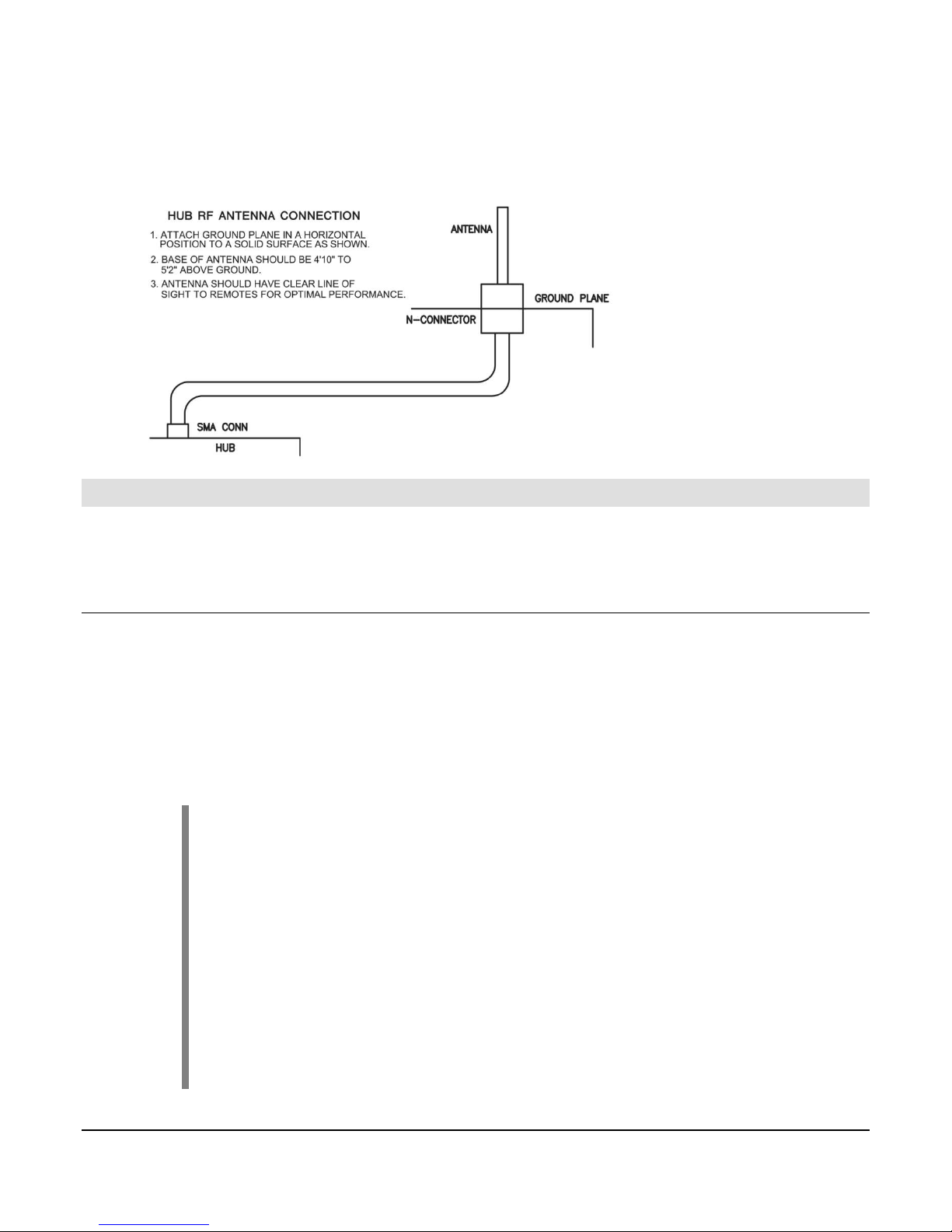
Installing the M2 Wireless Hub and Antenna
1. Mount the M2 Hub on a DIN rail inside the
panel enclosure.
The M2 Hub can be mounted vertically or
horizontally on a standard DIN rail. Two
clamp-type feet along the bottom of the hub
attach to the DIN rail, however, rail stops
are recommended to prevent sliding.
2. Add power to the hub by attaching a power cable to the GND/BAT pins and connecting
to a battery or power supply. Voltage must be between 8-32 volts DC.
3. Mount the antenna bracket to the top of the panel, or other structure, no more than 25
feet away from the hub.
4. Attach the coax cable to the Primary Antenna connection on the hub. Feed cable down
and outside of the panel through one of the conduit holes.
Section 50 00-02-0674
10-24-08 - 3 -
5. Attach the cable to the antenna through the mounting bracket, locking the antenna into
place.
Hub Activation
Connect PC cable to RS-485 connection on the hub. Use the MODBUS configuration software
on the PC to program the network address.
Program the Network Address
1. Verify the Hub is powered up.
2. To enable MODBUS writes, send a value of 0x1234 to MODBUS address 53
3. Set the network address by sending a unique value to MODBUS address 51
4. Verify that the value was programmed via the MODBUS map.
IMPORTANT!
Network address must be programmed before Learn Mode can be
enabled.
It is the installer’s responsibility to maintain a list of network addresses at
the location.
Each hub must have a unique address.
It is recommended that network addresses be offset by values of 5.
The highest network address is 255.

Section 50 00-02-0674
10-24-08 - 4 -
Hub Power Up – No Remotes Added Yet
• The ‘Heartbeat’ LED will start flashing on a periodic basis.
• All of the ‘Output’ LED’s will be off
• If there is MODBUS communication with the Hub, then the MODBUS LED’s will be
flashing; otherwise they will be off.
• The ‘Form C’ output will be shorted between ‘COM’ & ‘NC’ after the Hub has been
powered up for 2 seconds.
Hub Power Up – Remotes Already Added
• The ‘Heartbeat’ LED will start flashing on a periodic basis.
• All of the ‘Output’ LED’s will be off for at least 90 seconds.
• If there is MODBUS communication with the Hub, then the MODBUS LED’s will be
flashing; otherwise they will be off.
• The ‘Form C’ output will be shorted between ‘COM’ & ‘NO’ until all Remotes have
reported in.
• As soon as all Remotes report in subsequent to Hub power up, then the ‘Form C” output
will be shorted between ‘COM’ & ‘NC’.
• In the event all Remotes do not report in within 90 seconds, the ‘Output’ LED(s)
corresponding to the Remote(s) that have not reported in will be illuminated and the
‘Form C’ output will not change state.
Hub Power Up – VBAT Less Than 6.6 Volts but Greater Than 5.0 Volts
• The ‘Heartbeat’ & ‘Misc’ LED’s are on and do not go off.
• hen VBAT > 6.6 volts, the ‘Misc’ LED will go off and the ‘Heartbeat’ LED will start
flashing on a periodic basis.

Section 50 00-02-0674
10-24-08 - 5 -
Hub – How to Reset the Hub to Factory Defaults
• Power up the Hub.
• On the Hub, write a value of 0x1234 to MODBUS address 53 to enable MODBUS
writes.
• On the Hub, write a value of 0x2355 to MODBUS address 99.
• ait at least 5 seconds.
• Turn off Hub power.
• ait at least 10 seconds.
• Turn Hub power back on.
Section 50 00-02-0674
10-24-08 - 6 -
Installing Remote Units
Using the MODBUS program, determine the next remote ID by looking at MODBUS addresses
7 and 8. If 7 and 8 are not the same, then view the remote MODBUS map and look for an
unused location. If 7 and 8 are the same, then the next remote location will be the next
number after the value in 7 and 8.
You will want to label each remote unit with its corresponding Hub LED number and MODBUS
address.
NOT : The first 8 remote units correspond to Hub LEDs 1 through 8.
Additional remotes will use LED 8 to display any errors.
hen an error occurs, the hub will light up the appropriate LED 1 through
8.
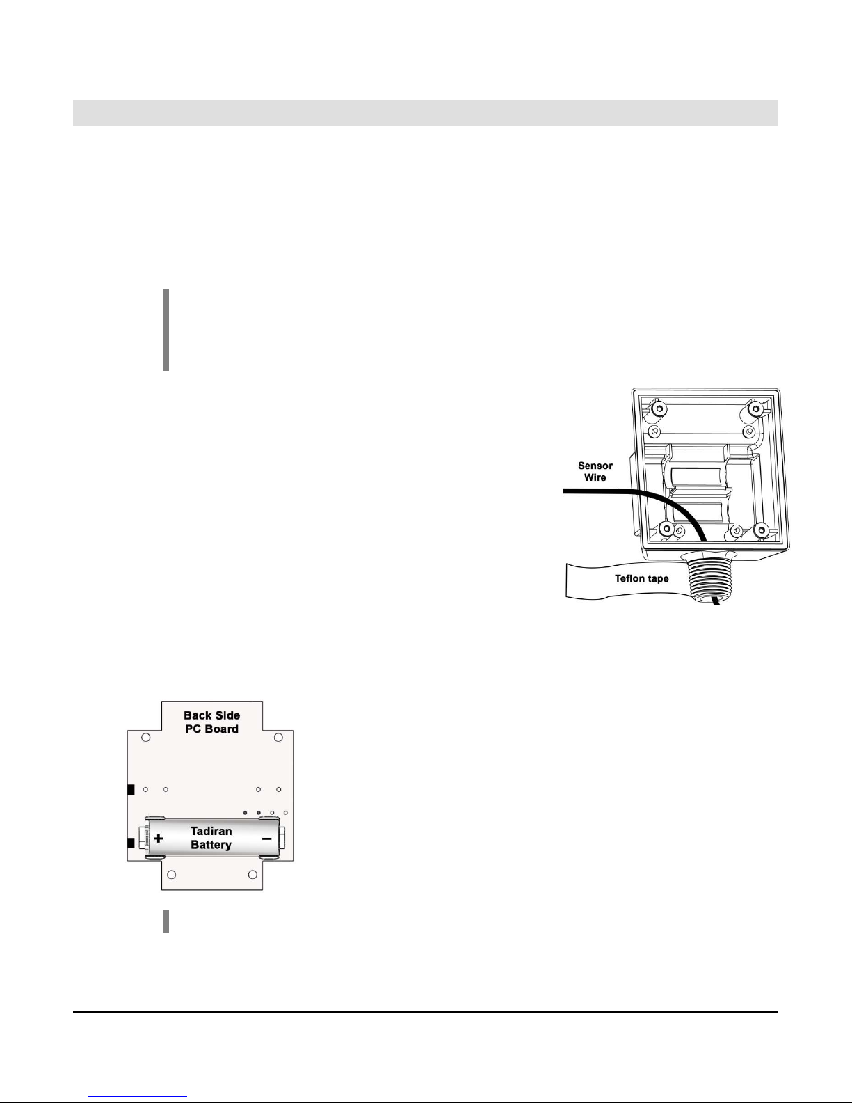
1. Loosen the 4 screws and remove the lid to the remote
enclosure. Take out the PC board and place it onto the
lid. Set aside for later.
2. Place 2 wraps of Teflon tape in a clockwise fashion
around threaded connection.
3. Run sensor wires into the remote case, leaving
approximately 1 foot of extra wire outside of the case.
4. Attach the remote case to the sensor or conduit, leaving
the case opening face up.
5. Snap the battery into place on the back side of the pc board,
aligning the +/- as indicated below.
NOT : Use only Tadiran TL-5903-S 3.6 volt Lithium batteries.
6. Replace the PC board into the casing, battery side down.
Other manuals for M2
1
Table of contents
Popular Antenna manuals by other brands

Alfa Network
Alfa Network APA-L01 Specifications

Naval
Naval PR-422CA Operation manual

Feig Electronic
Feig Electronic ID ISC.ANTH200/200 Series manual

TERK Technologies
TERK Technologies TV44 owner's manual

Directive Systems & Engineering
Directive Systems & Engineering DSE2324LYRMK quick start guide

HP
HP J8999A instructions


CommScope
CommScope CMAX-OMFX-43M-I53 Installation instruction

Ramsey Electronics
Ramsey Electronics DAP25 Kit assembly and instruction manual

COBHAM
COBHAM SAILOR 800 VSAT Replacement procedure

Trango Systems
Trango Systems AD900-9 Specification sheet

Steren
Steren ANT-100 user manual

Proxim
Proxim 5054-PA-23 quick start guide