manuals.online logo
Brands
  1. Home
  2. •
  3. Brands
  4. •
  5. Naval
  6. •
  7. Antenna
  8. •
  9. Naval Nargentus User manual

Naval Nargentus User manual

Other Naval Antenna manuals

Naval CAS 3500 User manual

Naval

Naval CAS 3500 User manual

Naval Mark 30ALC User manual

Naval

Naval Mark 30ALC User manual

Naval TDA-3 Technical document

Naval

Naval TDA-3 Technical document

Naval Mark 30ALC User manual

Naval

Naval Mark 30ALC User manual

Naval PS16 User manual

Naval

Naval PS16 User manual

Naval Mark 20CA User manual

Naval

Naval Mark 20CA User manual

Naval PR-422CA User manual

Naval

Naval PR-422CA User manual

Popular Antenna manuals by other brands

DAVIS Windex AV 3160 installation instructions

DAVIS

DAVIS Windex AV 3160 installation instructions

Belden Hirschmann BAT-ANT-N-14G-IP23 Mounting instruction

Belden

Belden Hirschmann BAT-ANT-N-14G-IP23 Mounting instruction

Vtronix YHK Fitting instructions

Vtronix

Vtronix YHK Fitting instructions

KVH Industries TracVision 6 Technical manual

KVH Industries

KVH Industries TracVision 6 Technical manual

Leica Geosystems GS10 user manual

Leica Geosystems

Leica Geosystems GS10 user manual

Sirio Antenne Gain-Master manual

Sirio Antenne

Sirio Antenne Gain-Master manual

Sony VCA-41 Installation/connections

Sony

Sony VCA-41 Installation/connections

ZCG Y100 Series installation guide

ZCG

ZCG Y100 Series installation guide

Advantech Wireless INTREPID120 Assembly instructions

Advantech Wireless

Advantech Wireless INTREPID120 Assembly instructions

Cerio ANT-10AO installation guide

Cerio

Cerio ANT-10AO installation guide

Alfa Network APA-L01 Specifications

Alfa Network

Alfa Network APA-L01 Specifications

Feig Electronic ID ISC.ANTH200/200 Series manual

Feig Electronic

Feig Electronic ID ISC.ANTH200/200 Series manual

TERK Technologies TV44 owner's manual

TERK Technologies

TERK Technologies TV44 owner's manual

TERK Technologies SIR3 owner's manual

TERK Technologies

TERK Technologies SIR3 owner's manual

Directive Systems & Engineering DSE2324LYRMK quick start guide

Directive Systems & Engineering

Directive Systems & Engineering DSE2324LYRMK quick start guide

HP J8999A instructions

HP

HP J8999A instructions

MobilSat MSP-S Mounting instructions

MobilSat

MobilSat MSP-S Mounting instructions

Steren ANT-UHF 13 instruction manual

Steren

Steren ANT-UHF 13 instruction manual

manuals.online logo
manuals.online logoBrands
  • About & Mission
  • Contact us
  • Privacy Policy
  • Terms and Conditions

Copyright 2025 Manuals.Online. All Rights Reserved.

Since 1971, the objective of Naval Electronics has been to offer the
best possible products for TV and Radio reception at sea. Naval
began with omnidirectional antennas and is the world leader in this
field of technology today. Now, with an expanded product range, the
name Naval means much more than antennas. Naval operates in
more than 40 countries and has installations on thousands of
vessels all over the world.
All specifications stated are subject to change without notice.
Naval Electronics AB
Höjdrodergatan 18, SE-212 39 Malmö, Sweden
Tel. +46(0)40-29 20 45. Fax +46(0)40-18 74 13
E-mail: sales@naval.se Web:www.naval.se
0710
3036
Size: (H) 636 x (W) 400
Nargentus is an digital omni-directional, wideband TV-AM-FM
receiving antenna (0.1 - 890 MHz) for marine use, especially on
crafts equipped with one or two radio and T\/ sets; e.g. on coasters
in limited international trade, fishing-boats, tugs, pilot service and
rescue cruisers.
Nargentus is a newly designed low profile antenna, utilizing a
low-noise amplifier powered via the coaxial cable.
High efficiency suppression filters prevent interference from
VHF telephone and AIS transmitters.
The antenna’s exterior is made of composite light-weight
material in white finish which requires no maintenance.
All inner parts are embedded in polyurethane foam to
protect the antenna from vibrations and water and it is
tested by Det Norske Veritas.
Connections, bolts and antenna
elements are made of stainless
acidproof steel.
The advantages of Nargentus compared to an
ordinary Yagi antenna are
•Rigid, non-corrodible, maintenance-free
construction
•Small dimensions, easy to mount
•Omni-receiving, no adjustments
The amplifier increases the sensitivity of the
system as well as compensates for cable-
losses in the antenna downlead.
The circuitry is protected against static charge.
Nargentus is delivered with 25 metres of 75
ohms low loss double shielded coaxial cable.
© Copyright 2001 Naval Electronics AB
TV-AM-FM Digital Antenna Nargentus
TECHNICAL SPECIFICATIONS
Frequency range
AM:
TV/FM:
Average gain:
Noise figure:
Max. output level:
Supply voltage to antenna:
Current consumption:
Surge
AM:
TV/FM:
CE-EMC:
Temperature range:
Connectors:
Weight:
Wavetraps
VHF:
AIS:
Certifiaction notes
Det Norske Veritas, DNV
Vibration test:
Material
Housing only:
Elements:
0.1 - 30 MHz
40 - 890 MHz
25 dB
max 4.5 dB
110 dBµV
(2 signals-60 dB IMA)
15 V DC ± 10%
approx 165 mA
6 kV
6 kV
EN 50083-2, EN 610003-2-2000
EN 61000-3-3:1995+A1:2001
-40o- +60o C
75 ohm BNC female
1 kg
156 MHz
162 MHz
IEC 60068-2-6, April 2005
Nylon66+glasfibre IP68
Stainless acidproof steel (A4/SUS304)
®
Order No. 201.780
In knockdown version
to be assembled
Incl. PS16
Shipping weight. 3 kg
Standard package: 1
Boxsize: 13 dm3
Antenna unit
The antenna should be mounted as high as possible and placed
away from masts and funnels and not in same level as radio
communication antennas and radars to avoid reflections and
interference. The superior location is at the masthead, with free
path in all directions. The antenna can be mounted on a 1.5" —2"
or 40—50 mm mast tube, deckmounting flange or mounting
bracket. The coaxial cable downlead should be well protected and
secured to the mast. Unload the downlead cable by means of cable
clamps and protect it from mechanical damage. Avoid outdoor cable
joints, but if necessary, make sure it is waterproof by using self-
vulcanizing rubber tape or similar. Avoid excessive bending at the coaxial
cable. Factors, such as transmitting power, polarization, radiation angle
and antenna height affect the received signal strength and picture quality.
Installation of the PS16 power supply
A.Mount the power supply indoors on the bulkhead by
means of two screws. If PS16 is to be mounted on a steel bulkhead, the
chassis on the power supply must be galvanic isolated from the
bulkhead. Don´t forget to use plastic bushing to isolate all the mounting
screws.
Note. The PS16 Power supply is not waterproof.
Do not connect the supply voltage until the installation is completed.
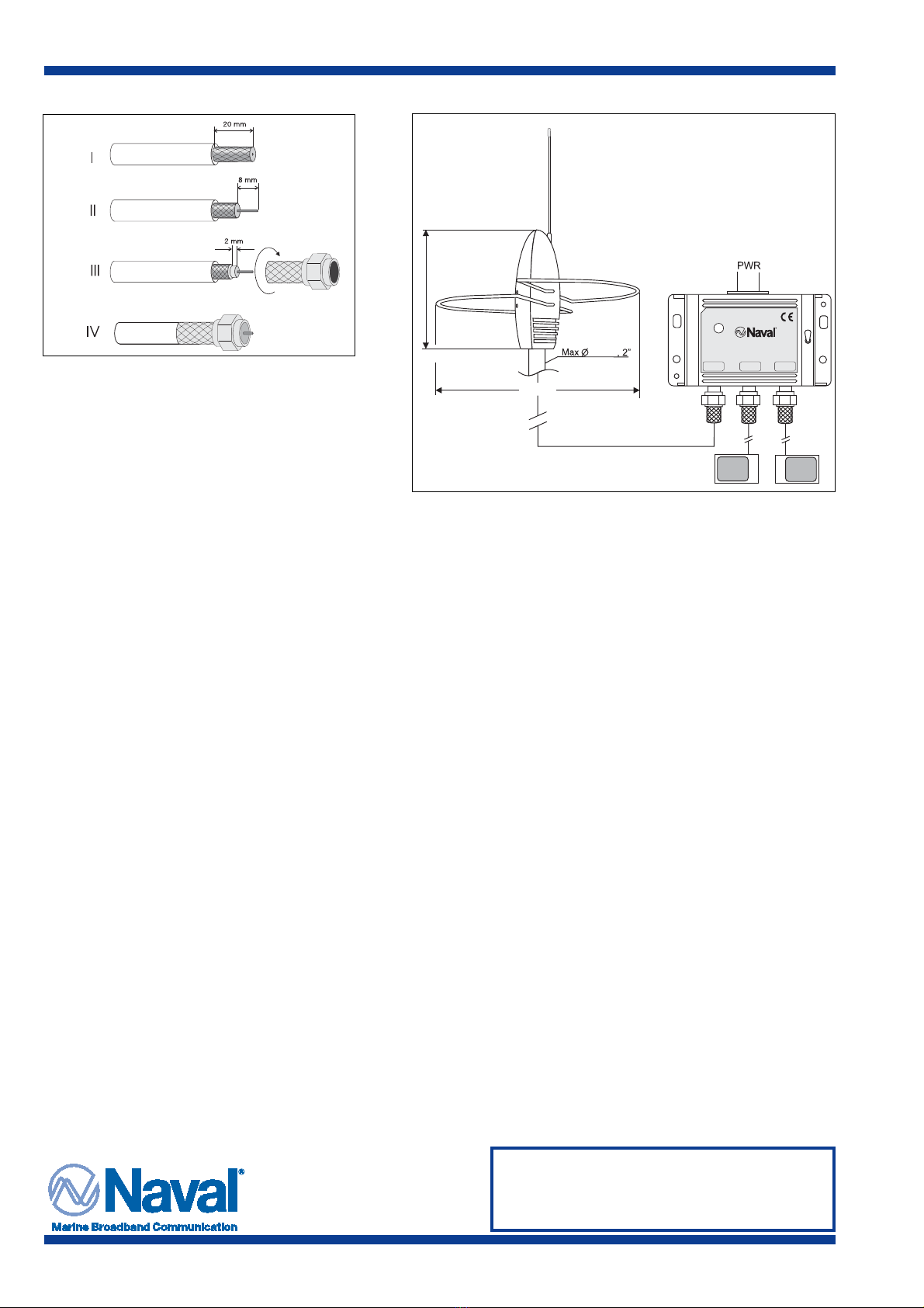
B.Strip the downlead coaxial cable and twist on the
F-connector, see fig. 1. Make sure that no parts of the braid are short-
circuiting the inner conductor. Connect the cord to the terminal marked
“antenna”. See fig.2.
Strip the TV/Radio coaxial cable and twist on the F-connector.
Connect the cord to one of the terminals marked “TV/Radio output” or
use the enclosed 1.5 m TV cord with F-IEC TV connectors.
Note. To achieve optimum performance, it is essential that the total cable
length (between antenna and TV/Radio-set) is not longer than 25 m
(80 ft). The coaxial cable must be a low loss double shielded
75 ohm type. Secure the coaxial cable by means of clamps and avoid
excessive bends and sharp edges.
Always terminate any unused TV/Radio output with the supplied
terminator plug for optimum result.
C.Connect the supply voltage input to the terminals marked
GND and +. The terminal accepts 12—30 V DC.
Install the fuseholder with a T400 mA fuse in the positive branch of
the power cable. If AC is required please use a local adapter.
Note. Inspect the completed installation. Check supply voltage and
polarity before switch on. Turn the switch on the right side of PS16
to activate the built in amplifier of the antenna.
D.Tune your TV/Radio-set and check sound/picture quality.
Note. In some ports severe reflections from buildings, cranes etc.
can cause distortion due to the nature of the omni-directional
receiving antenna.
In some areas, close to transmitters, overloading of the amplifier
and/or TV/Radio-set might occur.
Under these cirumstances do not interfere with the installation or the
TV/Radio-set.
Accessories
Deckmounting flange in stainless steel: 38mm
Diameter: 105 mm, 4.2"
Height: 60 mm, 2.4"
Mounting bracket in stainless steel 38mm
Length: 395 mm, 16"
Height: 100 mm, 4"
Trouble shooting
If the system is not working properly, please check the
following:
1.Proper supply voltage to power supply.
2.Connections.
3.Output voltage from power supply (should be 15 V DC ±10% ).
4.Antenna current (approx. 165 mA).
Fig 2
Fig 1
TV-AM-FM Digital Antenna Nargentus®
12-30 V DC IN
50 mm
400 mm
240 mm
GND
SUPPLY VOLTAGE
ON
ANTENNA
15V/165mA
PS16 POWER SUPPLY
Part no. 201.621
POWER ON
TV/RADIO
OUTPUT 1
TV/RADIO
OUTPUT 2
OFF
12 - 30 V DC
Naval Electronics AB Malmö, Sweden
+
-