MUSKOX 23-78 User manual

0
MODEL NUMBER: 23-78 AND 23-78 DUALLY
TO LOCATE YOUR SERIAL NUMBER, SEE PAGE 3
SERIAL NUMBER (Record Below): 601 First Street North
Mentor, MN 56736
PH: 218.288.1905
WEB: www.muskoxmn.com
operators manual
models
23-78 AND 23-78 DUALLY
TYPOGRAPHY
ACCENT PIECE
HEADINGS
BODY
Roboto bold
Roboto thin
C: 6
M: 0
Y: 97
K: 0
NEAREST PANTONE: 3945 C
R: 255
G: 255
B: 0
#FFFF00
C: 73
M: 67
Y: 65
K: 78
NEAREST PANTONE: BLACK C
R: 26
G: 26
B: 26
#1A1A1A
COLORS
ICON
PRIMARY LOGO
SECONDARY LOGOS
UPDATED SEPTEMBER 2022
ABSTRACT MARK
Open sans

2MUSKOX OPERATOR’S MANUAL MUSKOX MODELS 23-78 AND 23-78 DUALLY
Welcome to
the Family
Congratulations on the purchase of your Muskox
snowblower -- the snowblower that backdrags!
We hope it provides years of dependable service
for your snow removal needs.
Ron & Adam Bergman
Muskox Founders & Owners

MUSKOX OPERATOR’S MANUAL3
MUSKOX MODELS 23-78 AND 23-78 DUALLY
TABLE OF CONTENTS
PREFACE .......................................4
Safety Statements ...........................5
General Safety Precautions. . . . . . . . . . . . . . . . . .5
Equipment Safety Precautions ..............7
Safety Decal Locations. . . . . . . . . . . . . . . . . . . . 8-9
LIFT POINTS...................................10
TIE DOWN POINTS ...........................11
INSTALLATION AND SETUP ..................12
Hydraulic Connections ....................13
OPERATION...............................14-15
BACK DRAG POLES ...........................16
ADJUSTABLE RUBBER CUTTING EDGE ......17
LEVELING WHEEL.............................18
CHAIN TENSIONER ...........................19
GENERAL STORAGE ..........................20
BOLT TORQUE SPECIFICATIONS .............21
MAINTENANCE ...............................22
Grease Points ..............................22
Maintenance Videos.......................23
TROUBLESHOOTING .........................24
WARRANTY ...................................25
SERIAL NUMBER LOCATION

4MUSKOX OPERATOR’S MANUAL MUSKOX MODELS 23-78 AND 23-78 DUALLY
PREFACE
BEFORE OPERATION
The primary responsibility for safety with equipment
falls to the operator. Make sure the equipment is op-
erated only by trained individuals that have read and
understand this manual. If there is any portion of this
manual or function you do not understand, contact
your local authorized dealer or manufacturer to ob-
tain further assistance. Keep this manual available for
reference. Provide this manual to any new owners and/
or operators.
SERVICE
Use only manufacturer replacement parts. Substitute
parts may not meet the required standards. Record the
model and serial number of your unit on the cover of
this manual. The parts department needs this informa-
tion to ensure that you receive the correct parts.
SOUND AND VIBRATION
Sound pressure levels and vibration data for this at-
tachment are inuenced by many different parameters;
some items are listed below (not inclusive):
• prime mover type, age, condition, with or with-
out cab enclosure and conguration
• operator training, behavior, stress level
• job site organization, working material condition,
environment
Based on the uncertainty of the prime mover, operator,
and job site, it is impossible to get precise machine and
operator sound pressure levels, or vibration levels for
this attachment.
GENERAL INFORMATION
This product was carefully designed and manufactured.
Only minor maintenance (such as cleaning and lubricat-
ing) is required to keep it in top working condition. Be
sure to observe all maintenance procedures and safety
precautions in this manual and on any safety decals
located on the product and on any equipment on which
the attachment is mounted.
WARNING!
Never let anyone operate this unit without
reading the “Safety Precautions” and “Oper-
ating Instructions” sections of this manual. Always
choose hard, level ground to park the vehicle on and set
the brake so the unit cannot roll.
NOTE: The illustrations and data used in this man-
ual were current (according to the information
available to us) at the time of printing, however, we re-
serve the right to redesign and change the attachment
as may be necessary without notication.
SAFETY ALERT &
WARNING SYMBOLS
These are the “Safety Alert & Warning
Symbols” used by this industry. These
symbols are used to warn of possible
injury. Be sure to read all warnings
carefully. They are included for your safety
and the safety of others working with you.
Unless noted
otherwise, right
and left sides are
determined from
the operator’s control position
when facing the attachment.

MUSKOX OPERATOR’S MANUAL5
MUSKOX MODELS 23-78 AND 23-78 DUALLY
CAUTION
Caution indicates a hazardous situation which,
if not avoided, could result in minor or moderate
injury.
NOTICE
Notice indicates information considered
important, but not hazard-related (e.g. messages
relating to property damage).
This symbol by itself or used with a warning
word throughout this manual is used to call
your attention to instructions involving your personal
safety or the safety of others. Failure to follow these
instructions can result in injury or death.
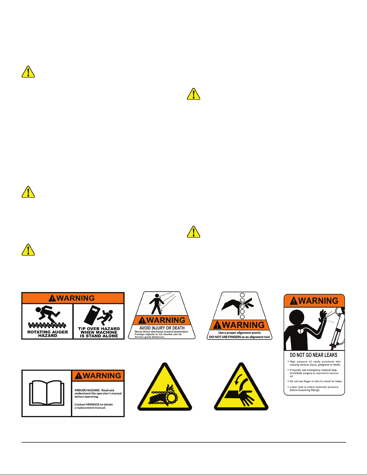
SAFETY DEFINITIONS
The purpose of safety symbols is to attract your
attention to possible dangers. The safety symbols,
and their explanations, deserve your careful attention
and understanding. The safety warnings do not by
themselves eliminate any danger. The instructions
or warnings they give are not substitutes for proper
accident prevention measures.
DANGER
Danger indicates a hazardous situation which, if
not avoided, will result in death or serious injury.
WARNING
Warning indicates a hazardous situation which,
if not avoided, could result in death or serious
injury.
SAFETY STATEMENTS
General Safety Precautions
READ MANUAL
PRIOR TO INSTALL
Improper installation, operation, or
maintenance of this equipment could result in
serious injury or death. Operators and maintenance
personnel should read this manual as well as all
manuals related to this equipment and the prime mover
thoroughly before beginning installation, operation, or
maintenance. FOLLOW ALL SAFETY INSTRUCTIONS
IN THIS MANUAL AND THE PRIME MOVER’S
MANUAL.
READ AND UNDERSTAND
ALL SAFETY STATEMENTS
Read all safety decals and safety statements
in all manuals prior to operating or working on
this equipment. Know and obey all OSHA regulations,
local laws and other professional guidelines for your
operation. Know and follow good work practices when
assembling, maintaining, repairing, mounting, removing
or operating this equipment.
KNOW YOUR EQUIPMENT
Know your equipment’s capabilities, dimensions
and operations before operating. Visually
inspect your equipment before you start, and never
operate equipment that is not in proper working order
with all safety devices intact. Check all hardware to
assure it is tight. Make certain that all locking pins,
latches, and connection devices are properly installed
and secured. Remove and replace any damaged,
fatigued or excessively worn parts. Make certain all
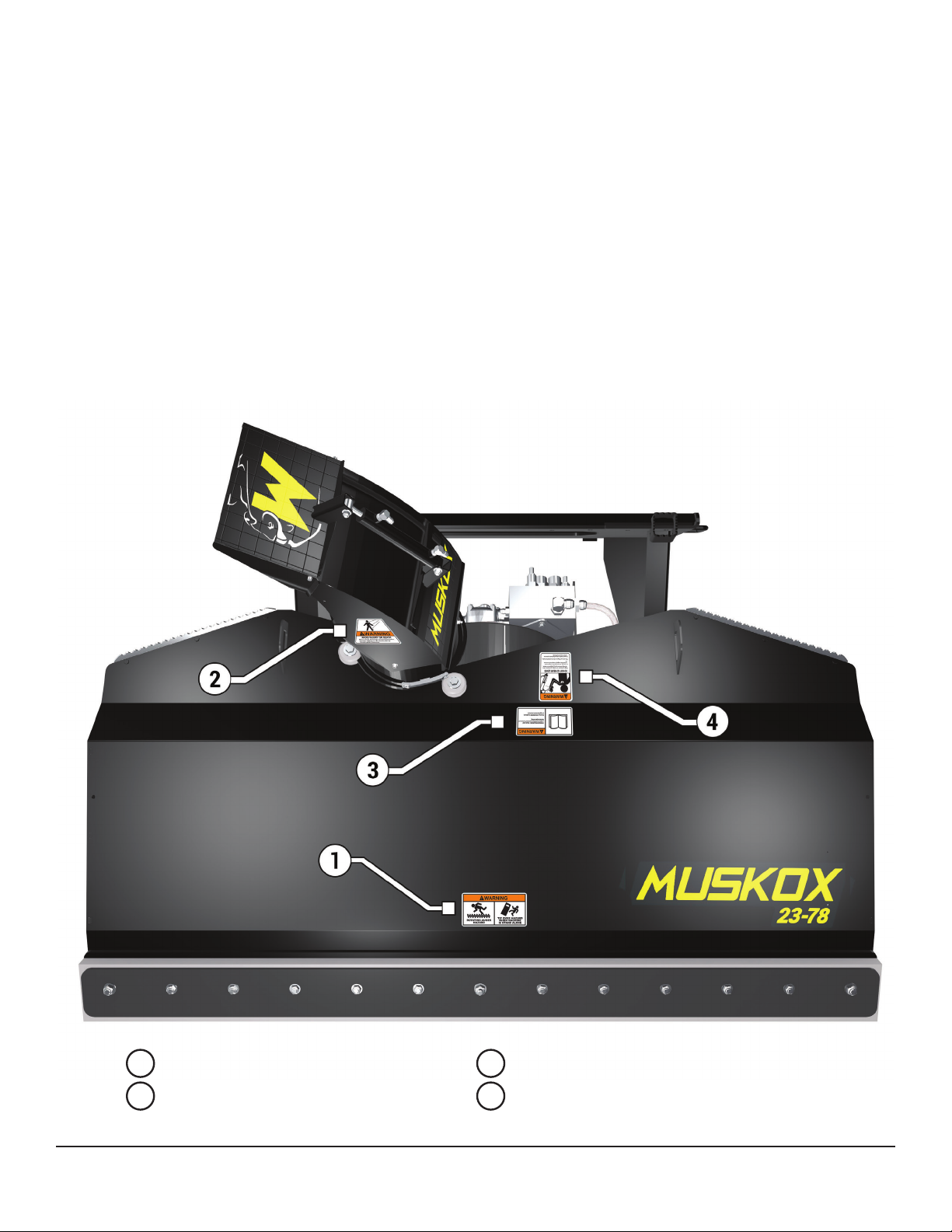
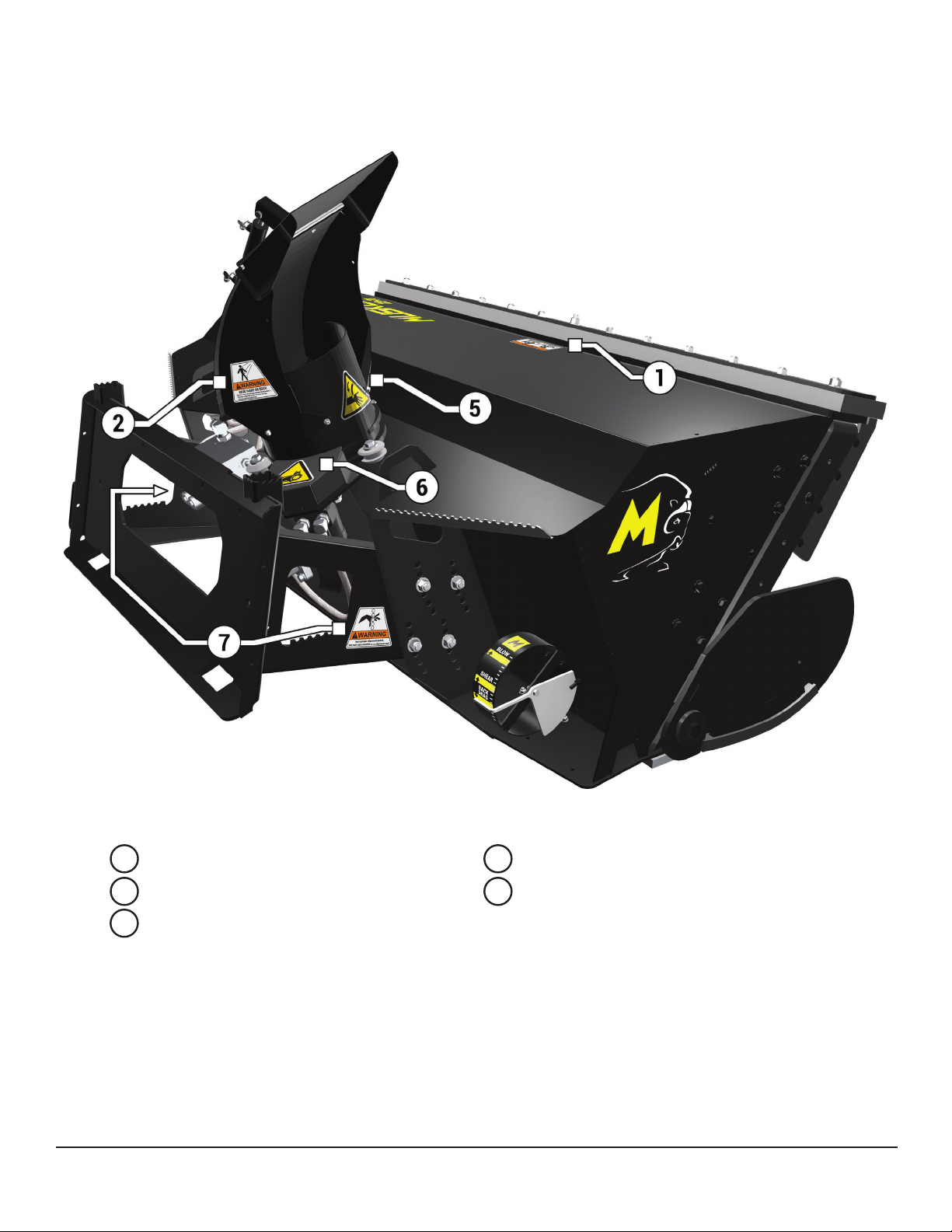
safety decals are in place and are legible. Keep decals
clean, and replace them if they become worn and hard
to read. (Safety decal replacements are available free
of charge from the manufacturer).
PROTECT AGAINST
FLYING DEBRIS
Always wear proper safety glasses, goggles
or a face shield when driving pins in or out or
when operation causes dust, ying debris, or any other
hazardous material.
LOWER OR SUPPORT
RAISED EQUIPMENT
Do not work under raised booms without
supporting them. Do not use support material
made of concrete blocks, logs, buckets, barrels or any
other material that could suddenly collapse or shift

6MUSKOX OPERATOR’S MANUAL MUSKOX MODELS 23-78 AND 23-78 DUALLY
positions. Make sure support material is solid, not
decayed, warped, twisted, or tapered. Lower booms
to ground level or onto blocks. Lower booms and
attachments to the ground before leaving the cab or
operator’s station.
DO NOT MODIFY MACHINE
OR ATTACHMENTS
Modications may weaken the integrity of the
attachment and may impair the function, safety,
life and performance of the attachment. When making
repairs, use only the manufacturer’s genuine parts,
following authorized instructions. Other parts may be
substandard in t and quality. Never modify any ROPS
(Roll Over Protection System) equipment or device.
Any modications must be authorized in writing by the
manufacturer.
SAFELY MAINTAIN
AND REPAIR EQUIPMENT
Do not wear loose clothing, or any accessories
that can catch in moving parts. If you have
long hair, cover or secure it so that it does not become
entangled in the equipment.
• Work on a level surface in a well-lit area.
• Use properly grounded electrical outlets and
tools.
• Use the correct tool for the job at hand. Make
sure they are in good condition for the task
required.
• Wear the protective equipment specied by the
tool manufacturer.
SAFELY OPERATE EQUIPMENT
Do not operate equipment until you are
completely trained by a qualied operator
in how to use the controls, know its capabilities,
dimensions, and all safety requirements. See your
prime mover’s manual for these instructions.
• Keep all step plates, grab bars, pedals, and
controls free of dirt, grease, debris, and oil.
• Never allow anyone to be around the equipment
when it is operating.
• Do not allow riders on the attachment or the
prime mover.
• Do not operate the equipment from anywhere
other than the correct operator’s position.
• Never leave equipment unattended with the
engine running or with this attachment in a
raised position.
• Do not alter or remove any safety features from
the prime mover or this attachment.
• Know your work site safety rules as well as
trafc rules and ow. When in doubt on any
safety issue, contact your supervisor or safety
coordinator for an explanation.
USE CARE WITH HYDRAULIC FLUID PRESSURE
Hydraulic uid under pressure can penetrate the skin
and cause serious injury or death. Hydraulic leaks under
pressure may not be visible. Before connecting or disconnecting
hydraulic hoses, read your prime movers operator’s manual for
detailed instructions on connecting and disconnecting hydraulic
hoses or ttings.
• Keep unprotected body parts, such as face, eyes, and arms
as far away as possible from a suspected leak. Flesh injected
with hydraulic uid may develop gangrene or other perma-
nent disabilities.
• If injured by injected uid, see a doctor at once. If your doc-
tor is not familiar with this type of injury, ask him to research
immediately to determine proper treatment.
• Wear safety glasses, protective clothing, and use a sound
piece of cardboard or wood when searching for hydraulic
leaks.
DO NOT USE YOUR HANDS!

MUSKOX OPERATOR’S MANUAL7
MUSKOX MODELS 23-78 AND 23-78 DUALLY
EQUIPMENT SAFETY PRECAUTIONS
REMOVE PAINT BEFORE
WELDING OR HEATING
Hazardous fumes/dust can be generated when
paint is heated by welding, soldering or using a
torch. Do all work outside or in a well-ventilated area
and dispose of paint and solvent properly. Remove
paint before welding or heating.
When sanding or grinding paint, avoid breathing the
dust. Wear an approved respirator. If you use solvent
or paint stripper, remove stripper with soap and water
before welding. Remove solvent or paint stripper
containers and other ammable material from area.
Allow fumes to disperse at least 15 minutes before
welding or heating.
END OF LIFE DISPOSAL
At the completion of the useful life of the unit,
drain all uids and dismantle by separating the
different materials (rubber, steel, plastic, etc.). Follow
all federal, state and local regulations for recycling and
disposal of the uid and components.
KNOW WHERE UTILITIES ARE
Observe overhead electrical and other utility
lines. Be sure equipment will clear them. When
digging, call your local utilities for location of buried
utility lines, gas, water, and sewer, as well as any other
hazard you may encounter.
ROTATING OBJECTS
Never allow anyone to reach into, kick into,
or otherwise come in contact with a rotating
auger or with a non-rotating clogged auger. The auger
can crush and/or dismember. Keep everyone clear of
the auger until the prime mover engine is off and the
hydraulic pressure has been relieved.
Never allow anyone to reach into the chute, force
objects (i.e. bars, poles, etc.) down the chute, kick into
the fan, or otherwise come in contact with a rotating
fan or with a non-rotating clogged fan. The fan can
throw objects at a lethal speed and can dismember.
Keep everyone clear of the fan until the prime mover
engine is off and the hydraulic pressure has been
relieved.
AVOID PINCH POINTS
Avoid pinch points and be aware of rotating
parts when manually turning the fan or auger.
SAFETY DECALS
0309-115
WARNING: Rotating Auger
WARNING: Tip Over Hazard
0309-109
WARNING: Flying Debris
0309-114
WARNING: Pinch Point
0309-116
WARNING: Read Manual
0309-102
WARNING: Chain
0309-101
WARNING: Rotating
Objects
0309-110
WARNING: High
Pressure Fluid

8MUSKOX OPERATOR’S MANUAL MUSKOX MODELS 23-78 AND 23-78 DUALLY
safety decal REPLACEMENT
INSTRUCTIONS
• Keep all safety signs clean and legible.
• Replace all missing, illegible, or damaged safety
signs.
• Replacement parts for parts with safety signs
attached must also have safety signs attached.
Safety signs are available, free of charge from
MUSKOX.
PLACEMENT OR REPLACEMENT
OF SAFETY SIGNS
1. Clean the area of application with non-
ammable solvent, and then wash the same area
with soap and water.
2. Allow the surface to fully dry.
3. Remove the backing from the safety sign,
exposing the adhesive surface.
4. Apply the safety sign to the position shown in the
diagram below and smooth out any bubbles.
safety decal LOCATIONS
AUGER/TIP OVER WARNING FLYING DEBRIS WARNING
READ MANUAL WARNING HIGH PRESSURE FLUID WARNING
1 2
3 4

MUSKOX OPERATOR’S MANUAL9
MUSKOX MODELS 23-78 AND 23-78 DUALLY
safety decal LOCATIONS
AUGER/TIP OVER WARNING FLYING DEBRIS WARNING
ROTATING OBJECTS WARNING CHAIN WARNING
PINCH POINT WARNING
1 2
5 6
7

10MUSKOX OPERATOR’S MANUAL MUSKOX MODELS 23-78 AND 23-78 DUALLY
LIFT POINTS
Lift Points are identied in the image below. Lifting
at other points is unsafe and can damage attach-
ment. Do not attach lifting accessories around
cylinders or in any way that may damage hoses or
hydraulic components.
USE LIFTING ACCESSORIES
(CHAINS, SLINGS, ROPES, SHACK-
LES AND ETC.) THAT ARE CAPABLE OF
SUPPORTING THE SIZE AND WEIGHT
OF YOUR ATTACHMENT. Secure all lifting
accessories in such a way to prevent un-
intended disengagement. Failure to do so
could result in the attachment falling and
causing serious personal injury or death.
• Attach lifting accessories to unit at recom-
mended lifting points.
• Bring lifting accessories together to a central
lifting point.
• Lift gradually, maintaining the equilibrium of
the unit.

MUSKOX OPERATOR’S MANUAL11
MUSKOX MODELS 23-78 AND 23-78 DUALLY
TIE DOWN POINTS
Tie down points are identied in the diagram
below. Securing to trailer at other points is unsafe
and can damage attachment. Do not attach tie
down accessories around cylinders or in any way
WARNING! VERIFY THAT ALL TIE DOWN ACCESSORIES (CHAINS, SLINGS, ROPES, SHACKLES AND
ETC.) ARE CAPABLE OF MAINTAINING ATTACHMENT STABILITY DURING TRANSPORTING and are
attached in such a way to prevent unintended disengagement or shifting of the unit. Failure to do so could result
in serious personal injury or death.
that may damage hoses or hydraulic components.
• Attach tie down accessories to unit as
recommended.
• Check unit stability before transporting.

12MUSKOX OPERATOR’S MANUAL MUSKOX MODELS 23-78 AND 23-78 DUALLY
installation and setup
INSTALLATION & SETUP
1. Place the product on a rm, level surface
that is large enough to safely accommodate
this product, your prime mover and all work-
ers involved in the mounting process.
2. Refer to the operator’s manual(s) for your
prime mover, loader, and quick-attach and
follow the mounting instructions contained
therein.
3. Carefully raise the loader and cycle the tilt
cylinders to check clearances and to verify
that all mounting procedures have been suc-
cessfully completed.
Lubricate all grease ttings before
connecting this product to your
prime mover’s hydraulic system.
Refer to the MAINTENANCE section on
page 22, and follow the instructions
READ MANUAL PRIOR
TO INSTALLATION
Improper installation, operation, or maintenance
of this equipment could result in serious injury
or death. Operators and maintenance personnel
should read this manual, as well as all manuals re-
lated to this equipment and the prime mover thor-
oughly before beginning installation, operation, or
maintenance. FOLLOW
ALL SAFETY INSTRUC-
TIONS IN THIS MANUAL
AND THE PRIME MOV-
ER’S MANUAL(S).
2. Remove the nut from the POSITIVE (+) cable
clamp on the battery and slide the RED wire
ring terminal from the wiring harness cable
over the positive (+) cable clamp bolt. Secure
the ring terminal with the nut.
3. Remove the nut from the NEGATIVE (-) ca-
ble clamp on the ground cable and slide the
BLACK wire ring terminal from the wiring
harness cable over the negative (-) cable
clamp bolt.
4. Reinstall the ground cable on the negative
post of the battery and secure the ring
terminal and the ground cable with the nut
removed in the previous step.
5. Secure the wiring harness cable from the
battery to the control box with your nylon
cable ties.
6. Feed the wiring harness cable: a) back to the
left-rear area of your prime mover, b) past
the loader arm’s rear hinge point by follow-
ing the hydraulic hoses where possible, and
c) down the loader arm following the hydrau-
lic lines.
7. Allow sufcient slack in the cable at the
hinge point to provide for a full range of
motion of the loader arms. Use your nylon
cable ties to secure the cable to the loader
frame below the hinge point and back to the
control box.
WIRING HARNESS
INSTALLATION
1. Remove the ground cable from the negative
(-) post of your prime mover’s battery.
WARNING! Failure to obey the following proce-
dures could result in death or serious injury. Before
doing any work on your prime mover’s battery, read
and understand all prime mover instructions and
safety signs for your prime mover’s electrical sys-
tem. Pay special attention to hazard avoidance and
remedial action related to explosive gas and acid.
AVOID ELECTRIC SHOCK! Failure to obey all
procedures may result in personal injury. To avoid
electrical shock during the wiring harness installa-
tion, remove the ground cable from the battery of
your prime mover.

MUSKOX OPERATOR’S MANUAL13
MUSKOX MODELS 23-78 AND 23-78 DUALLY
HYDRAULIC SNOW BLOWER
HYDRAULIC CONNECTION
1. Disconnect the hydraulic hose quick cou-
plers from one another and attach the quick
couplers to your prime mover as per the
instructions in your prime mover operator’s
manual.
2. Carefully raise the loader and cycle the tilt
cylinders to check hose clearances and to
check for any interference. Operate the
HYDRAULIC CONNECTIONS
READ AND UNDERSTAND
ALL SAFETY STATEMENTS
Read all safety decals and safety statements in all manuals before
beginning any Snow Blower hydraulic connection. Know and obey all
OSHA regulations, local laws, and other professional guidelines for your
operation. Know and follow good work practices when assembling,
maintaining, repairing, mounting, removing, or operating this equip-
ment.
WARNING! Do not lock the auxiliary hydraulics of your prime mover in
the “ON” position. Failure to obey this warning could result in death or
serious injury.
chute and deector on this product to make
the same checks.
3. Cycle the hydraulic cylinder(s) on this prod-
uct several times from fully retracted to fully
extended until all air has been completely
removed from the cylinder(s).
WARNING! Do not lock the auxiliary hy-
draulics of your prime mover in the “ON”
position. Failure to obey this warning could result
in death or serious injury.

14MUSKOX OPERATOR’S MANUAL MUSKOX MODELS 23-78 AND 23-78 DUALLY
OPERATION
INTENDED USE
This snow blower has been designed and built to
push loose snow. Use in any other way is consid-
ered contrary to the intended use. Compliance
with and strict adherence to operation, service and
repair conditions as specied by the manufacturer,
are also essential elements of the intended use.
Never allow anyone to reach into, kick into,
or otherwise come in contact with a rotat-
ing auger or with a non-rotating clogged auger.
The auger can crush and/or dismember. Keep
everyone clear of the auger until the prime mover
engine is off and the hydraulic pressure has been
relieved.
Never allow anyone to reach into the chute,
force objects (i.e. bars, poles, etc.) down
the chute, kick into the fan, or otherwise come in
contact with a rotating fan or with a nonrotating
clogged fan. The fan can throw objects at a lethal
speed and can dismember. Keep everyone clear of
the fan until the prime mover engine is off and the
hydraulic pressure has been relieved.
Never place any object (i.e. bar, pole, stick,
etc.) down the chute until the prime mover
engine is off and the hydraulic pressure has been
relieved.
Do not operate this product until all others are
clear of the entire discharge area. Foreign objects
and pieces of ice are generally thrown farther
than snow. High ow snow blowers are capable of
throwing material up to up to 120 feet.
Do not operate this product when blowing or
thrown snow restricts visibility.
Do not lock the auxiliary hydraulics in the “ON”
position.
Never lift this product a) above the operator’s eye
level or b) to a height where visibility is obstructed,
whichever is lower.
Be aware that turning off the power unit
key does not cut the power to the winch or
to the actuator. With the switches for these de-
vices being powered 100 percent of the time, care
must be taken to not engage these switches:
a) Accidentally at any time, especially when
entering or leaving the prime mover
operator’s position, or
b) When others are working on or near the
actuator, the deector, the winch, the chute,
or any other part of this product that could
cause personal injury if the switches are
engaged.
Holding the toggle switches in the powered po-
sition after the actuator has reached the end of
that device’s cycle of movement, and/or
• Applyingforceonthedeectorfromany
source, other than blown snow, that will
causethedeectortoeithercompressor
extendthedeector’sactuator,and/or
• Using your Snow Blower as a snow “plow”
CAN result in damage to this product and
WILL void all MUSKOX warranties.
READ AND UNDERSTAND ALL
SAFETY STATEMENTS
Read all safety decals and safety
statements in all manuals prior to
operating or working on this equip-
ment. Know and obey all OSHA regulations,
local laws, and other professional guidelines
for your operation. Know and follow good
work practices when assembling, maintaining,
repairing, mounting, removing, or operating
this equipment.
NOTICE

MUSKOX OPERATOR’S MANUAL15
MUSKOX MODELS 23-78 AND 23-78 DUALLY
Always rotate the chute and adjust the de-
ector so that the thrown snow is directed
into open areas.
Never direct the discharge at buildings, automo-
biles, trees, or any other item that may be dam-
aged by thrown snow.
When blowing snow, approach the snow with the
wind at the operator’s back whenever possible.
When clearing a large area, cut the rst pass on
the upwind side and work downwind.
If an excessive amount of snow is being pushed in
front of the auger housing, SLOW DOWN!! Allow
the auger and fan enough time to properly collect
and throw the snow.
If a foreign object becomes wedged in the auger,
the auxiliary hydraulics on the prime mover may
be reversed to reverse the auger. Reversing the
auger rotation may remove the obstruction.
If a foreign object becomes wedged in the fan:
a) Move to a level surface, place your prime
mover’s transmission in “Park” and engage
the parking brake.
b) Lower this product onto the level surface.
c) Shut off your prime mover’s engine, remove
the starter key, wait for all moving parts to
come to a stop, and relieve all pressure in the
hydraulic lines.
d) Disconnect the hydraulic ttings from your
prime mover and reconnect those ttings to
each other.
e) The fan can then be manually turned in a
reverse rotation, allowing the foreign object
to be removed.
f) Once the fan is free, reconnect the hydraulic
ttings as per the instructions in the
HYDRAULIC CONNECTION section of this
manual.
OPERATION

16MUSKOX OPERATOR’S MANUAL MUSKOX MODELS 23-78 AND 23-78 DUALLY
Back Drag Poles
Back drag poles are identied in the image be-
low. The poles are designed as reference point
for the distance between the front rubber cutting
edge and the obstruction in front of said cutting
rubber edge. The poles are designed to serve as a
reference point only, as any slight adjustment can
greatly affect distance and accuracy.
• Back drag pole is adjustable to 4 distance
points ranging from roughly 5 inches to 13
inches. Adjustment of distance is deter-
mined by U-bolt placement. Location of
U-bolt in reference to distance from obstruc-
tion is referenced below.
• To install or replace back drag poles, slide
poles through holes on either end of blow-
er as indicated on the picture, with blower
tipped back in forward blow position, install
U-bolts supplied around stake from inside
the blower. Slide pole down until 37 inches
exposed above blower.
• Replacement poles are available for order at
service@muskoxmn.com

MUSKOX OPERATOR’S MANUAL17
MUSKOX MODELS 23-78 AND 23-78 DUALLY
Adjustable Rubber Cutting Edge
Rubber cutting edge is identied in the diagram
below. The rubber cutting edge is designed to
reduce scratching of hard surfaces. The perfor-
mance of the rubber cutting edge is improved by
operator angle and location of the cutting edge
in reference to upper steel plate that secures the
rubber.
• When setting the rubber cutting edge, the
exposed rubber between the upper steel
plate and edge of rubber should be 3/4".
Reference the image below when adjusting
rubber cutting edge or replacing.
• To extend the life of the rubber cutting edge,
it is designed to have 4 usable edges, addi-
tionally the rubber cutting edge is adjust-
able.
• We recommend measuring the amount of
exposed rubber before each use, and adjust-
ing as needed.
• For video on how to adjust or replace the
cutting edge, visit www.muskoxmn.com/
maintenance
• Adjustable rubber cutting edges are avail-
able for order at service@muskoxmn.com

18MUSKOX OPERATOR’S MANUAL MUSKOX MODELS 23-78 AND 23-78 DUALLY
Leveling Wheel
Leveling wheel is identied in the diagram below.
The leveling wheel is designed as a reference point
only and reference three positions: blow, sheer
and back drag. The leveling wheel is for reference
only as any slight adjustment can greatly affect
distance and accuracy. The line of sight for the lev-
eling wheel may vary based on the drive machine,
seated position of operator and position of snow
blower.
• The leveling wheel three position points,
blow, sheer and back drag are identied in
the image below. When the silver pin of lev-
eling wheel, identied below, is in the middle
of the larger yellow sticker below each posi-
tion, the operator is in the reference point.
• Operating outside of suggested reference
points may lead to additional wear and tear
of machine.
• For video showing how to replace or add a
leveling wheel to a MUSKOX blower, go to
www.muskoxmn.com/maintenance?
• Leveling wheel are available for order at
service@muskoxmn.com

MUSKOX OPERATOR’S MANUAL19
MUSKOX MODELS 23-78 AND 23-78 DUALLY
Chain Tensioner
Chain tensioner is identied in the diagram be-
low. The chain tensioner is found only on our dual
auger model. It is designed to maintain the perfor-
mance of the upper auger. OEM chain that comes
with standard with belower is 50 grade.
• The chain tensioner is adjustable, we rec-
ommend it be set at 2 inches from front of
tensioner as identied in the image below.
• We recommend checking tightness of chain
before each use.
• For video showing how to adjust chain
tensioner or replace, go to www.muskoxmn.
com/maintenance
• Chain tensioner and chain are available for
order at service@muskoxmn.com

20MUSKOX OPERATOR’S MANUAL MUSKOX MODELS 23-78 AND 23-78 DUALLY
STORAGE
• Unit must be stored in the downward (back
drag) position.
• Clean the unit thoroughly, removing all snow,
dirt and grease.
• Inspect for visible signs of wear, breakage or
damage. Order any parts required and make
the necessary repairs to avoid delays upon
removal from storage.
• Tighten loose nuts, capscrews and hydraulic
connections.
• Coat exposed portions of the cylinder rods
with grease.
• Lubricate grease ttings.
• Seal hydraulic system from contaminants
and secure all hydraulic hoses off the ground
to help prevent damage.
• Store unit in a dry and protected place.
Leaving the unit outside will materially
shorten its life.
• Touch up all unpainted surfaces with paint to
avoid rust.
REMOVAL FROM STORAGE:
• Remove cover.
• Wash unit and replace any damage and/or
missing parts.
• Lubricate grease ttings.
• Check hydraulic hoses for damage and
replace as necessary.
• Check chain adjuster and tighten as needed.
GENERAL STORAGE
This manual suits for next models
1
Table of contents