Muuntosahko Superintend Trafox VR-16 User manual

Superintend VR-16
Residual current relay for 5-wire network
Short operating manual
Revision history:
Version 1.0 New document
Version 1.1 -
Table of Contents
1Preface....................................................................................................................................... 2
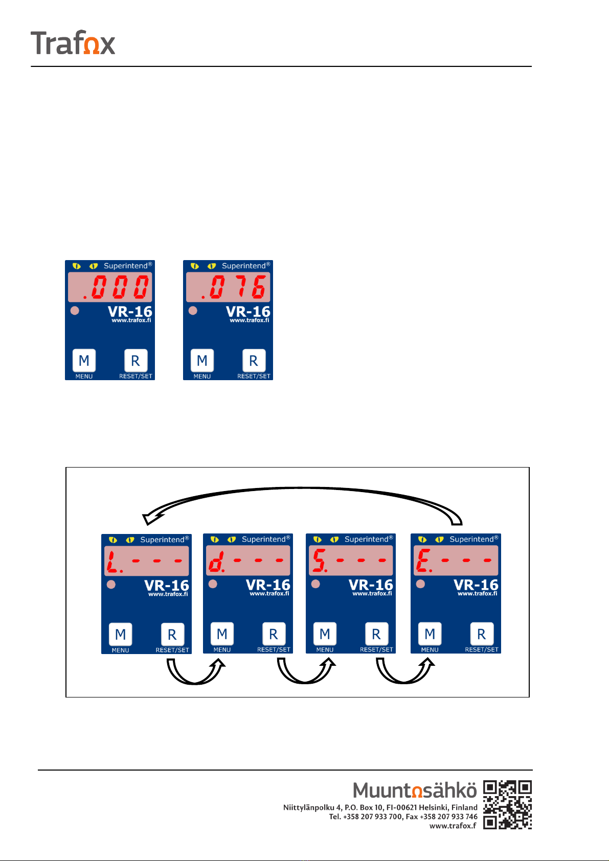
2Menu selections ........................................................................................................................ 2
2.1 Limit Menu ( L ) ................................................................................................................... 3
2.2 Delay Menu ( d ).................................................................................................................. 4
2.3 Sensor Menu ( S ) ................................................................................................................ 5
2.4 Error Memory ( E ) .............................................................................................................. 6
3Modes during operation............................................................................................................ 6
3.1 Normal operation ............................................................................................................... 6
3.2 Alarm................................................................................................................................... 7
3.3 Warning............................................................................................................................... 7
3.4 Sensor fault ......................................................................................................................... 8
4Acknowledging fault modes ...................................................................................................... 8

VR-16 –short operating manual Feb 8, 2017
2/8 Version 1.0
1Preface
This instruction describes briefly the operation and use of the user interface.
2Menu selections
The device is in its basic mode when the current sensor is connected and power is switched
on. Power is not supplied through the current sensor (Figure 1) or, when the current is
below the set fault limit, the display shows sensor current (Figure2).
Figure 1 Basic mode. Figure 2 Current below set limit in basic mode.
Go to menus from the basic mode by keeping M (Menu) button pressed down. When you
keep pressing down the M button, you browse through menus at short delay intervals.
Select a menu by releasing the M button when the desired menu is displayed.
Figure 3 When the M (Menu) button is kept down, you browse between menus at a short delay interval.
Select the menu by releasing the M (Menu) button.

VR-16 –short operating manual Feb 8, 2017
3/8 Version 1.0
2.1 Limit Menu ( L )
Once Limit Menu is selected, the display shows the current set value. Go from one
selection to another by pressing the M button briefly. Confirm your selection by pressing R
(Reset / set) button for a long time. Once a selection is confirmed, you return to the basic
mode. The limit value choices available are 30mA, 100mA, 300mA, 500mA, 1A, 3A or 10A
(Figure 4).
Figure 4 Selecting limit value with short presses of the M (Menu) button. Confirm your selection by
pressing R (Reset / set) button for a long time.

VR-16 –short operating manual Feb 8, 2017
4/8 Version 1.0
2.2 Delay Menu ( d )
Once Delay Menu is selected, the display shows the current set value. Go from one
selection to another by pressing the M button briefly. Confirm your selection by pressing R
(Reset / set) button for a long time. Once a selection is confirmed, you return to the basic
mode. The delay choices available are 100ms, 500ms, 1s, 3s, 5s or 10s (Figure 5).
Figure 4 Selecting delay time with short presses of the M (Menu) button. Confirm your selection by
pressing R (Reset / set) button for a long time.

VR-16 –short operating manual Feb 8, 2017
5/8 Version 1.0
2.3 Sensor Menu ( S )
Once Sensor Menu is selected, the display shows the current set value. Go from one
selection to another by pressing the M button briefly. Confirm your selection by pressing R
(Reset / set) button for a long time. Once a selection is confirmed, you return to the basic
mode. Sensor choices available are 25A, 35A, 60A, 95A, 130A or 200A (Figure 6).
Figure 6 Selecting sensor with short presses of the M (Menu) button. Confirm your selection by pressing
R (Reset / set) button for a long time.

VR-16 –short operating manual Feb 8, 2017
6/8 Version 1.0
2.4 Error Memory ( E )
Once Error Memory is selected, the display shows the current set value. Go from one
selection to another with short presses of the M button (Figure 7). Confirm your selection
by pressing R (Reset / set) button for a long time. Once a selection is confirmed, you return
to the basic mode. The selection allows you to choose whether the device will remember
the error mode after power returns. ON mode means that the error mode is remembered
when power returns even if it no longer is valid and OFF mode means that switching off
power resets the fault mode if the fault is removed.
Figure 7 Selecting error memory ON / OFF with short presses of the M (Menu) button. Confirm your
selection by pressing R (Reset / set) button for a long time.
3Modes during operation
3.1 Normal operation
The device is in its basic mode when the current sensor is connected and power is switched
on. Power is not supplied through the current sensor (Figure 8). When the current is below
the fault limit, the display shows sensor current (Figure9). You can go from basic mode to
Menu selection.

VR-16 –short operating manual Feb 8, 2017
7/8 Version 1.0
Figure 8 Basic mode. Figure 9 Current below set limit in basic mode.
3.2 Alarm
Alarm mode is active when the current exceeds the set limit and the overrun lasts longer
than the set delay. In alarm mode, the display is as shown in Figure 10. Alarm is indicated
by the letter A and a blinking LED light. In alarm mode the relay is released. The value of
measured current is 158mA.
Figure 10 Display in alarm mode
3.3 Warning
When the current exceeds the set current limit, the display will be as shown in Figure 11.
Warning is indicated by the letter P and blinking LED light. The warning mode is active if the
current exceeds the set limit but the overrun is shorter than the set delay. The value of
measured current is 158mA.
Figure 11 Display in warning mode

VR-16 –short operating manual Feb 8, 2017
8/8 Version 1.0
3.4 Sensor fault
If the sensor is missing or the device cannot test the sensor for other reasons, the device
will issue a fault notification. The display will be as shown in Figure 12. Fault is indicated by
the letter F and a blinking LED light. In fault mode the relay is released.
Figure 12. Display indicates a sensor fault.
4Acknowledging fault modes
Fault modes can be acknowledged by pressing the R (reset / set) button for a long time.
Acknowledging is only possible if the fault mode has been removed.
The fault mode can also be acknowledged by using off the device's voltage for sufficiently
long while the Error Memory setting is in OFF position.
Table of contents