MW TZHD30S User manual

M1.1.TZHD30S-50S.NLFREN - 15032019
HANDLEIDING - MODE D’EMPLOI - MANUAL
TZHD30S (790031754)
TZHD50S (790032182)
Tafelzaag
Scie à table
Table saw
P.02 Gelieve te lezen en voor later gebruik bewaren
P.19 Veuillez lire et conserver pour consultation ultérieure
P.36 Please read and keep for future reference
FR
EN
NL
copyrighted document - all rights reserved by FBC

2
NL
M1.1.TZHD30S-50S.NLFREN - 15032019
1 Veiligheid
De veiligheidssymbolen zijn bedoeld om uw aandacht te vestigen op mogelijke gevaarlijke omstandigheden. Deze handleiding
gebruikt een reeks symbolen en woorden om het belang van veiligheidsberichten aan te geven. Het verloop van de symbolen
wordt hieronder beschreven:
GEVAAR!
Wijst op een dreigende gevaarlijke situatie die, indien niet vermeden, de dood of ernstige letsels kan veroorzaken.
WAARSCHUWING!
Wijst op een mogelijke gevaarlijke situatie die, indien niet vermeden, de dood of ernstige letsels kan veroorzaken.
AANDACHT!
Wijst op een mogelijke gevaarlijke situatie die, indien niet vermeden, lichte of matige verwondingen kan veroorzaken.
Kan ook gebruikt worden om praktijken aan te pakken die geen verband hebben met het risico op letsels.
OPMERKING
Symbool dat gebruikt wordt om de gebruiker nuttige informatie te geven over de juiste werking van de machine.
!
Inhoud
1 Veiligheid ������������������������������������������������������������������������������������������������������������������������������������������2
1.1 Veiligheidsvoorschriften ...................................................................................................................................3
1.2 Veiligheidsvoorzieningen.................................................................................................................................4
2 Omschrijving van de machine ������������������������������������������������������������������������������������������������������������5
2.1 Technische gegevens.......................................................................................................................................5
2.2 Omschrijving van de machineelementen ............................................................................................................6
2.3 Toepasselijk gebruik........................................................................................................................................6
2.4 Vereisten voor stroomvoorziening......................................................................................................................7
2.5 Geluidsniveau ................................................................................................................................................7
3 Installatie van de machine �����������������������������������������������������������������������������������������������������������������8
3.1 Transport van machines ...................................................................................................................................8
4 Instellingen�������������������������������������������������������������������������������������������������������������������������������������� 14
5 Bediening ���������������������������������������������������������������������������������������������������������������������������������������� 16
5.1 Elektriciteit ...................................................................................................................................................16
5.2 Voorzorgmaatregelen voor gebruik .................................................................................................................16
5.3 Bediening ....................................................................................................................................................16
5.4 Dwarssnijden ...............................................................................................................................................16
5.5 Langssnijden ................................................................................................................................................16
6 Onderhoud �������������������������������������������������������������������������������������������������������������������������������������� 17
7 Storingen oplossen �������������������������������������������������������������������������������������������������������������������������� 18
8 Onderdelen �������������������������������������������������������������������������������������������������������������������������������������53
9 EG conformiteitsverklaring���������������������������������������������������������������������������������������������������������������62
copyrighted document - all rights reserved by FBC

3
NL
M1.1.TZHD30S-50S.NLFREN - 15032019
1�1 Veiligheidsvoorschriften
Algemene veiligheidsvoorschriften
• Ken uw machine. Lees en begrijp de handleiding en de op de machine aangebrachte etiketten. Leer meer over de
toepassingen en beperkingen en de specieke potentiële gevaren.
• Aard de machine. Elektrocutie, brand of materiële schade kunnen optreden als de machine niet goed elektrisch
aangesloten en geaard is.
• Houd de werkruimte schoon en goed verlicht. Rommelige of donkere plaatsen zijn een bron van ongelukken.
• Houd kinderen en andere personen uit de buurt terwijl de machine in bedrijf is. Door verstrooidheid kunt u de controle
verliezen. Alle bezoekers moeten op een veilige afstand van de werkruimte gehouden worden.
• Kinderen zijn niet toegelaten in de werkplaats. Ongeschoolde gebruikers lopen het risico op zware of dodelijke letsels.
Laat alleen geschoolde/onder toezicht staande personen de machine bedienen.
• Koppel de machine altijd los alvorens de machine in te stellen of te onderhouden, of voordat u een gereedschap wisselt. Dit
voorkomt het risico op letsels bij onbedoeld opstarten of contact met onder spanning staande onderdelen.
• U kunt geschokt, verbrand of gedood worden door het aanraken van onder spanning staande onderdelen of onjuist
geaarde machine. Om dit risico te beperken, moeten alle werkzaamheden aan de elektrische installatie door een
gekwaliceerde elektricien uitgevoerd worden. Schakel de stroomtoevoer altijd uit voordat u toegang krijgt tot elektrische
apparatuur.
• Vermijd gevaarlijke omgevingen. Gebruik geen elektrisch gereedschap in vochtige ruimtes en stel het niet bloot aan regen.
Zorg voor een geschikte en goed verlichte werkruimte.
• Draag geschikt kleding. Draag geen losse kleding, handschoenen, stropdassen of sieraden (ring, horloge), omdat deze
in bewegende delen kunnen vast komen te zitten. Draag antislipschoenen. Bind lang haar samen. Rol de lange mouwen
boven de elleboog.
• Draag een veiligheidsbril. Een gewone bril is alleen schokbestendig maar geen veiligheidsbril. Draag ook een stofmasker
als uw werk stof produceert.
• Draag een gehoorbescherming bij het bedienen van lawaaierige machines. Langdurige blootstelling aan geluid zonder
bescherming kan leiden tot permanente gehoorverlies.
• De beschermingen en afdekkingen verminderen het risico van onbedoeld contact met bewegende of rondvliegende delen.
Maak zeker dat ze goed geïnstalleerd zijn, niet beschadigd en dat ze goed werken voordat u de machine gebruikt.
• Maak er een gewoon van om te controleren dat alle sleutels van de machine zijn verwijderd voordat u de machine
inschakelt.
• Zorg altijd voor een stabiele positie en een goede balans tijdens het werk. Vermijd onhandige handposities die het moeilijk
maken om het werkstuk onder controle te houden of het risico op onopzettelijke letsel te vergroten.
• Onderhoud het gereedschap zorgvuldig. Houd de gereedschappen schoon en scherp voor veilige prestaties. Volg de
instructies om de accessoires te smeren en te vervangen.
• Vermijd onbedoeld opstarten. Maak zeker dat de schakelaar op “Uit” staat voor het aansluiten van de machine.
• Gebruik het geschikt gereedschap. Forceer het apparaat of de accessoires niet voor werkzaamheden waarvoor ze niet
ontworpen zijn.
• Gebruik aanbevolen accessoires. Raadpleeg de handleiding voor de aanbevolen accessoires en volg de instructies van de
fabrikant. Het gebruik van ongeschikte accessoires kan naar gevaren leiden.
• Klim nooit op de machine. Gevaar voor zware letsels bij kantelen van de machine.
• Controleer voor ieder gebruik van de machine de goede werking van de beschermingen en andere onderdelen. Controleer
of de bewegende delen goed uitgelijnd zijn, of er geen gebroken onderdelen zijn, of alle onderdelen goed gemonteerd
en in goede staat zijn alvorens de machine te gebruiken. Beschadigde beschermingen of andere onderdelen moeten
gerepareerd of vervangen worden.
• Laat de machine nooit onbeheerd draaien. Zet de schakelaar op “Uit”. Verlaat het werkgebied niet totdat de machine
volledig tot stilstand gekomen is.
• Gebruik altijd een bescherming, een spouwmes en een terugslagvinger voor alle “doorzagen” operaties. Doosteekzagen
zijn de handelingen waarbij het zaagblad volledig door het werkstuk snijdt, zoals bij langssneden of dwarssneden.
• Houd het werkstuk altijd stevig vast tegen de verstekgeleider of langsgeleider.
• Gebruik altijd een duwstok op smalle stukken te zagen. Raadpleeg de instructies voor langssneden.
• Gebruik altijd de langsgeleider of verstekgeleider om het werkstuk te plaatsen en te geleiden.
• Sta nooit of laat nooit een deel van uw lichaam in lijn met het pad van het zaagblad.
• Reik nooit achter of onder het snijgereedschap, om welke reden dan ook.
• Verwijder de langsgeleider voor dwarssneden.
• Bij het snijden van sierlijsten mag het werkstuk nooit tussen de langsgeleider en de snijkop geleid worden. Raadpleeg de
instructies in de handleiding van het toebehoren voor het snijden van sierlijsten.
• Voedingsrichting. Voer het werkstuk naar het zaagblad in tegen de draairichting ervan.
copyrighted document - all rights reserved by FBC

4
NL
M1.1.TZHD30S-50S.NLFREN - 15032019
1�2 Veiligheidsvoorzieningen
Gebruik een duwblok (guur 2) of een duwstok (guur 3).
5.NEVER.
Never stand or have any part of your body in line
with the path of the saw blade;
6.NEVER REACH BEHIND.
Never reach behind or over the cutting tool with
either hand for any reason;
7. MOVE THE RIP FENCE.
Move the rip fence out of the way when
crosscutting;
8. DIRECTION OF FEED.
Feed work into the blade against the direction of
rotation;
9. NEVER.
Never use the fence as a cut-off gauge when you
are cross-cutting;
10. NEVER.
Never attempt to free a stalled saw blade without
first turning the saw OFF;
11. PROVIDE ADEQUATE SUPPORT.
To the rear and sides of the table saw for wide or
long work pieces;
12. AVOID KICKBACKS.
Avoid kickbacks (work thrown back towards you)
by keeping the blade sharp, by keeping the rip
fence parallel to the saw blade, by keeping the
splitter and anti-kickback fingers and guard in place
and operating, by not releasing work before it is
pushed all the way past the saw blade, and by not
ripping work that is twisted or warped or does not
have a straight edge to guide along the fence;
13. AVOID AWKWARD OPERATIONS.
Avoid awkward operations and hand positions
where a sudden slip could cause your hand to
move into the spinning blade;
14. BLADE REQUIREMENTS.
Only correctly sharpened saw blades
manufactured in accordance with the requirements
of EN 847-1:2005 shall be used;
15. SPEED.
No saw blade shall be used where the maximum
marked speed is lower than the maximum
rotational speed of the saw spindle;
16. CHIP AND DUST.
The machine shall be connected to an external
chip and dust extraction system;
The dust extraction equipment is to be switched on
before commencing machining;
17. CHECK
Period check the brake function to make sure the
stop time of the saw blade is less than 10s;
4.3 Residual risks
1. Take precautions to reduce the hazard of
inhalation of harmful dusts (e.g. wearing a dust
mask);
2. Wear ear protection to prevent hearing loss;
3. Always wear safety glasses. also use a face or
dust mask if cutting operation is dusty;
4. Against the hazard of cutting when handling
saw blades into the machine or doing
maintenance;
5. Not to try removing chips whilst the saw
blade(s) is (are) running and the saw unit(s) is
(are) not in the rest position;
6. Not to try using the machine unless all of the
guards and other safety devices necessary for
machining are in good working order;
4.3 Safety equipment
A push block (Fig.2) and A push stick (Fig.3)
must be used
Fig.2
Fig.3
If the workpieces is less then 120mm, you must
use the push stick to prevent your hands from
getting too close to the saw blade.
Push block must be used to cut narrow
workpieces and, when necessary, to push the
workpiece against the fence, a push block can
be easily made by the operator as Fig.2.
Figuur 1 Figuur 2
WAARSCHUWING!
Als het werkstuk kleiner is dan 120 mm, moet u een duwstok gebruiken, om te voorkomen dat
uw handen te dicht bij het zaagblad komen�
Een duwblok moet gebruikt worden om smalle werkstukken te zagen en, indien nodig, om
het werkstuk tegen de langsgeleider te duwen� Een blok kan gemakkelijk door de bediender
vervaardigd worden, zoals op guur 2 getoond.
Poignée
• Gebruik de langsgeleider nooit als lengteaanslag bij het uitvoeren van dwarssneden.
• Probeer nooit een vastzittend zaagblad los te maken zonder eerst de machine uit te schakelen.
• Zorg voor een geschikte ondersteuning aan de achterkant en zijkanten van de zaag voor lange of brede werkstukken.
• Vermijd terugslagen (werkstuk naar u toe geprojecteerd) door het zaagblad scherp te houden, de langsgeleider parallel
aan het zaagblad, het spouwmes, de terugslagvinger en de beschermkap goed op hun plaats te houden, door het
werkstuk niet los te laten zolang het niet volledig achter het zaagblad gepasseerd is, en door geen langssneden te maken
van een verdraaid of vervormd werkstuk, of zonder rechte rand om tegen de langsgeleider te geleiden.
• Vermijd delicate handelingen en de handposities waarbij een plotselinge verschuiving ertoe kan leiden dat de hand naar
het roterende zaagblad toe beweegt.
• Gebruik alleen scherpe zaagbladen die vervaardigd zijn volgens de bepalingen van EN 847-1:2005.
• Gebruik geen zaagblad waarvan het aangegeven toerental lager is dan het maximale toerental van de zaagas.
• De machine moet op een extern spaan- en stofafzuigsysteem aangesloten worden. De stofzuiger moet voor het begin van
de bewerking ingeschakeld worden.
• Controleer de werking van de rem regelmatig, om er zeker van te zijn dat het zaagblad in minder dan 10 seconden stopt.
Restrisico’s
1. Neem de nodige voorzorgmaatregelen om te voorkomen dat schakelijke stoffen ingeademd worden (bijv. door het dragen
van een stofmasker).
1. Draag een gehoorbescherming om gehoorverlies te voorkomen.
2. Draag altijd een veiligheidsbril. Draag ook een stofmasker als uw werk stof produceert.
3. Neem voorzorgmaatregelen om het risico van snijwonden te voorkomen wanneer u het zaagblad hanteert.
4. Probeer geen spanen te verwijderen terwijl het zaagblad draait en als de zaageenheid niet in ruststand is.
5. Gebruik de machine niet zolang alle afdekkappen en veiligheidsvoorzieningen niet geïnstalleerd zijn en goed werken.
copyrighted document - all rights reserved by FBC

5
NL
M1.1.TZHD30S-50S.NLFREN - 15032019
2 Omschrijving van de machine
2�1 Technische gegevens
Model TZHD30S TZHD50S
Machine afmetingen
Gewicht 260 kg (ongeveer)
L x l x h 1582 x 1100 x 1016
mm 2090 x 1100 x 1016
mm
Afstand tussen de voeten 508 x 508 mm
Elektrisch systeem Schakelaar Magnetisch met thermische beveiliging tegen
overbelasting
Moteur
Type TEFC inductiestartcondensator
Vermogen / Spanning / Fasen - A 4 kW (5,5 pK) / 380 V / 3 F - 8,3 A
Snelheid 2850 tpm
Vermogenstransmissie Drievoudige V-riem
Informatie over zaagblad
Maximum diameter zaagblad 250 mm
Dikte spouwmes 2,5 mm
Benodigde dikte van het bladlichaam 1,8 - 2,4 mm
Benodigde dikte van de zaagsnede 2,6 - 3,2 mm
Maximale groefbreedte 20,3 mm
Hellingshoek Links 0° - 45°
Asdiameter 30 mm
Assnelheid 4800 tpm
Aslagers Afgedicht en permanent gesmeerd
Zaagcapaciteit
Maximale snijdiepte bij 90° 70 mm
Maximale snijdiepte bij à 45° 50 mm
Maximale langssnede rechts van het
zaagblad 750 mm 1250 mm
Maximale langssnede links van het
zaagblad 305 mm
Informatie over de tafel
Afstand vloer - tafel 860 mm
Hoodftafel l x b x dikte 512 x 685 x 48 mm
Afstand tafelrand - midden van het
zaagblad 440 mm
Afstand tafelrand - blad van maximale
snede 310 mm
Verstekgeleider Type groef in verstekgeleider T-groef
Groef in verstekgeleider - b x h 19,05 x 9,525 mm
Andere informatie Verf Poederlak
Diameter afzuigmond 100 mm
copyrighted document - all rights reserved by FBC

6
NL
M1.1.TZHD30S-50S.NLFREN - 15032019
2�2 Omschrijving van de machineelementen
3.2 Feature Identification( Fig.1)
Fig.1
1
Rear rail
2
Main Table
3
Blade Guard
4
Right Extension Wing
5
Fence
6
Extension Table
7
Front rail & Tube
8
Leg
9
Motor Cover
10
Blade Height Hand Wheel
11
On/Off Switch
12
Dust Port
13
Blade Tilt Hand Wheel
3.3 Intended Use
Table saw and the workpiece guide equipment
supplied with it are intended to be used exclusively
for the following purposes:
●Laminated and unlaminated board materials (e.g.
chipboard, coreboard, MDF board, ...)
●Solid wood •
●Gypsum plasterboard • , Cardboard, Veneer with
a suitable clamping device
●Dimensionally stable plastics (thermoset plastics,
thermoplastics).Sawing these materials does not
normally involve any risks in respect of dust, chips,
and thermal degradation products.
Tools:
●The chosen saw blade must be suitable both for
the specific work cycle and for the specific material.
●Only circular blades which are solid chrome
vanadium (CV) or tungsten carbide tipped (TCT)
and have a diameter of 250mm , arbor size
30mm,as well as a maximum width of 20mm are
allowed for the main saw
●Saw blades made of high-alloy high-speed steel
(HSS) are not allowed to be used.
●Saw blades and their fixing devices shall conform
to EN 847-1:2005。
Site of installation/use:
●The machine is not suitable for use outdoors, or in
rooms that are subject to moisture or the risk of
explosions.
●The intended use of the machine involves
connection to a suitably dimensioned extraction
system .•
●Intended use also involves compliance with our
specified operating, maintenance and repair
conditions and the safety information contained in
the operating ins9tructions.
●The table saw may only be used, set up and
maintained by persons who are familiar with the
machine and aware of the dangers.
●The pertinent accident prevention regulations as
well as any other generally recognised technical
safety and industrial medicine rules must be
observed.
●Repair work must be carried out by our own
customer service or by an organization that we have
authorized. Only original spare parts are allowed to
be used for this. we will assume no warranty for any
damage that is caused by using non-original spare
parts.
The machine is prohibited to be used in a
potentially explosive atmosphere!
1. Achterrail
2. Hoofdtafel
3. Zaagbladbescherming
4. Rechter verlengstuk
5. Langsgeleider
6. Verlengtafel
7. Voorste rail + buis
8. Voet
9. Motorkap
10. Handwiel voor zaagbladhoogteinstelling
11. ON/OFF (AAN/UIT) schakelaar
12. Afzuigaansluiting
13. Handwiel voor zaagbladhelling
Figuur 3
2�3 Toepasselijk gebruik
De tafelzaag en meegeleverde geleiders zijn uitsluitend bestemd voor de volgende toepassingen:
• Gelamineerde en ongelamineerde materialen (bijv. spaanplaten, karton, MDF, ...),
• Massief hout,
• Gipsplaten, karton, neer met passende kleminrichting,
• Dimensionaal stabiele kunststoffen (thermohardende kunststoffen, thermoplasten). Het zagen van deze materialen houdt
normaal gesproken geen risico in van stof, spanen en thermische afbraakproducten.
Gereedschappen:
• Het zaagblad moet zowel voor de specieke werkcyclus als voor het specieke materiaal geschikt zijn.
• Alleen cirkelzaagbladen met chroom vanadium (CV) of wolfraamcarbide (TCT) tanden met een diameter van 250 mm, een
asgat van 30 mm en een maximale breedte van 20 mm zijn toegestaan.
• Hogesnelheidsstaal (HSS) zaagbladen van gelegeerd hooggelegeerd staal (High Alloy High Speed Steel) kunnen niet
worden gebruikt.
• De zaagbladen en hun bevestigingsmiddelen moeten voldoen aan EN 847-1:2005.
Plaats van installatie/gebruik:
• De machine is niet geschikt voor gebruik buitenshuis of in ruimten die aan vocht of explosiegevaar blootgesteld worden.
• Het toepasselijk gebruik van de machine behelst de aansluiting op een correct gedimensioneerd afzuigsysteem.
• Het toepasselijk gebruik behelst ook het naleven van de voorwaarden voor gebruik, onderhoud en reparatie, alsmede de
veiligheidsinstructies in de handleiding.
• De tafelzaag mag enkel gebruikt, ingesteld en onderhouden worden door personen die vertrouwd zijn met de machine en
bewust zijn van de gevaren.
• De relevante voorschriften ter voorkoming van ongevallen en andere algemeen erkende technische veiligheids- en
arbeidsgezondheidsvoorschriften
• Reparatiewerkzaamheden moeten door onze eigen klantendienst uitgevoerd worden, of door een door ons geautoriseerde
organisatie. Er mogen alleen originele reserveonderdelen gebruikt worden. Wij aanvaarden geen garantie voor schade
veroorzaakt door het gebruik van niet-originele reserveonderdelen.
WAARSCHUWING!
Het is verboden de machine in een mogelijk explosieve atmosfeer te gebruiken!
copyrighted document - all rights reserved by FBC

7
NL
M1.1.TZHD30S-50S.NLFREN - 15032019
2�4 Vereisten voor stroomvoorziening
Lijst van de meest gebruikte en voorbedrade spanningen:
Motor 4 kW (5,5 pK)
Spanning 380 V
Fasen 3 Ph
Frequentie 50 Hz
Nominale stroom 8,3 A
Voorbedrading 380 V / 3 F
Draden 5
De stabiele AC voeding is 0,9 ~ 1,1 maal de nominale waarde.
Frequentie
0,99 ~ 1,01 maal de nominale frequentie (50 Hz, continue werking)
0,98 ~ 1,02 maal de nominale frequentie (50 Hz, korte termijn werking)
Harmonischen
De som van de 2de - 5de harmonischen mag niet meer dan 10 % van de RMS spanningswaarde bedragen. Een aanvulling
van 2 de RMS waarde van de lijnspanning is toegestaan voor de som van de 6de tot de 30ste harmonischen.
Asymmetrische spanning
Noch de negatieve noch de nulsequentiecomponenten mogen meer dan 2 % van de positieve sequentiecomponent bedragen.
Elektrische beveiliging
De eindgebruiker moet zorgen voor een bliksembeveiliging en een kortsluitingsbeveiliging op de stroomvoeding.
Bescherming tegen indringen aan de ingang van de inkomende stroomkabel
De ingangsmethode van de ingangskabel moet bij de voltooiing van de installatie ter plaats een beschermingsgraad IP54
garanderen.
2�5 Geluidsniveau
Referentiestandaarden
De geluidsmetingen werden uitgevoerd volgens de norm EN ISO 11202 voor de bepaling van het geluidsdrukniveau
op de werkplekken. Wanneer de gemeten geluidsdrukniveaus op de werkplekken 85 dB(A) overschrijden, werden de
geluidsvermogenniveaus gemeten volgens EN ISO 3746.
Gebruiksvoorwaarden
De gebruiksvoorwaarden voor de geluidsmetingen zijn in overeenstemming met bijlage A van de norm ISO 7960:1995.
Testresultaten
ONBELAST BELAST
Lwa 101,3 104,1
Lpa
Positie A 84,7 88,5
Positie B 86,1 89,1
Positie C 77,0 79,8
Bijbehorende onzekerheid K= 4 dB
Opmerking: Het achtergrondgeluid van de meetomgeving bedraagt 65,0 dB(A)�
copyrighted document - all rights reserved by FBC

8
NL
M1.1.TZHD30S-50S.NLFREN - 15032019
De vermelde cijfers zijn emissieniveaus en zijn niet noodzakelijkerwijze veilige bedrijfsniveaus. Hoewel er een verband
bestaat tussen emissie- en blootstellingsniveaus, kan dit niet op betrouwbare wijze gebruikt worden om te bepalen of verdere
voorzorgsmaatregelen al dan niet noodzakelijk zijn. Factoren die het werkelijke niveau van blootstelling van het personeel
invloeden zijn onder meer de kenmerken van de werkplaats, andere geluidsbronnen, waaronder het aantal machines en
andere aangrenzende processen. Het toelaatbare niveau van blootstelling kan ook van land tot land verschillen. Deze
informatie stelt de bediener van de machine echter in staat om het gevaar en het risico beter in te schatten.
3 Installatie van de machine
3�1 Transport van machines
Transport en opslag
Roest- en schokbeschermende maatregelen moeten tijdens het verpakken genomen worden. De machine kan getransporteerd
en opgeslagen worden bij omgevingstemperaturen tussen -25 en +55 °C.
Stel de machine niet bloot aan regen en zorg ervoor dat de verpakking tijdens transport en opslag niet beschadigd raakt.
WAARSCHUWING!
Wees uiterst voorzichtig bij het transport of hanteren van de machine, en laat de werkzaamheden
door gekwaliceerd en speciaal opgeleid personeel uitvoeren!
Let er bij het laden en lossen van de machine op dat er geen personen of voorwerpen door de
machine verpletterd worden!
Transport voor het uitpakken
5. Installation of the machine
5.1 Transportation of machines
5.1.1 Transportation and store
The measures of anti-rust and shockproof should
be taken during packing. The machine endures
transportation and store in -25~55°C ambient
temperature.
Be care of not making machine exposed to rain or
damaging the packing during transportation and
store.
While transporting or handling the machine, be
careful and let the activity be done by qualified
personnel especially trained for this kind of
activity!
While the machine is being loaded or unloaded,
make sure that no person or subject gets
pressed by the machine!
Select proper transportation device according
to the weight of the machine. Make sure the
lifting capacity of transportation device is
competent for the weight of the machine.
5.1.2 Transportation before unpacking
As standard, the machine is packed in a robust
wooden box. Fig.4 shows the tool can be used to
transport the packing box.
Fig.4
5.2 Unpacking
your machine was carefully packaged for safe
transportation. remove the packaging materials
from around your machine and inspect it. if you
discover the machine is damaged, please
immediately call Customer Service for advice.
Save the containers and all packing materials for
possible inspection by the carrier or its agent.
Otherwise, filing a freight claim can be difficult.
5.3 Safety measure before installation
It is important to maintain free area of 0.8 m around
the machine, which is required for the working
place. If any long material is machined, it is
necessary to have a sufficient room in front of the
machine as well behind it in the places of material
input and output.
De machine wordt in een stevige houten kist geleverd. Figuur 4 toont een apparaat dat voor
het transport van de verpakte machine gebruikt kan worden.
3�2 De machine uitpakken
Uw machine werd zorgvuldig verpakt voor een veilig transport. Verwijder de verpakking
rond de machine en controleer deze. Als u vaststelt dat de machine beschadigd is, breng
dan onmiddellijk de klantendienst op de hoogte.
Bewaar de containers en alle verpakkingsmaterialen voor eventuele inspectie door de Figuur 4
vervoerder of een van zijn agenten. Anders zal het moeilijk zijn om een klacht in te dienen.
3�3 Veiligheidsmaatregelen voor installatie
Het is belangrijk om een vrije ruimte van 0,8 m rond de machine te behouden voor de werkplek. Als lange werkstukken
gezaagd moeten worden, is het noodzakelijk om voldoende ruimte voor en achter de machine te voorzien voor het in- en
afvoer van het werkstuk.
3�4 Installatie
Alvorens met de montage van de machine te beginnen, dient u de volgende voorzorgmaatregelen en suggesties in acht te
nemen:
De machine is aan de pallet vastgeschroefd. Verwijder alle onderdelen en ijzerwerk uit de machine en draai de
bevestigingsbouten los.
Vloer: Deze machine betekent een groot gewicht op een klein oppervlak. Zorg ervoor dat de vloer sterk genoeg is om het
gewicht van de machine en van de bediener te dragen. De vloer moet ook effen en horizontaal zijn. Als de machine oscilleert
of zwenkt na installatie, gebruik dan vulplaten om de machine te stabiliseren.
Werkruimte: Houd rekening met de grootte van de werkstukken. Zorg voor voldoende ruimte om de machine vrij te kunnen
bedienen.
Plaats van het stopcontact: De stopcontacten moeten dicht genoeg bij de machine geplaatst worden, zodat niemand op
de stroomkabel of het verlengsnoer kan struikelen. Volg alle elektrische regels als u nieuwe circuits en/of stopcontacten moet
installeren.
copyrighted document - all rights reserved by FBC

9
NL
M1.1.TZHD30S-50S.NLFREN - 15032019
5.4 installation
Before beginning assembly, take note of the
following precautions and suggestions.
The machine is bolted to the pallet, before
attempting any of the assembly procedures
remove all of the loose parts and hardware from
the inside of the machine and unbolt the machine
from the pallet.
----- FLOOR: This tool distributes a large amount of
weight over a small area. Make certain that the
floor is capable of supporting both the weight of the
machine and the operator. The floor should also be
a level surface. If the unit wobbles or rocks once in
place, be sure to eliminate by using shims.
-----WORKING CLEARANCES: Take into
consideration the size of the material to be
processed. Make sure that you allow enough
space for you to operate the machine freely.
-----OUTLET PLACEMENT: Outlets should be
located close enough to the machine so that the
power cord or extension cord is not in an area
where it would cause a tripping hazard. Be sure to
observe all electrical codes if installing new circuits
and/or outlets.
DO NOT assemble the machine until you are
certain that the machine is not plugged in and
the power switch is in the OFF position.
DO NOT connect the machine to the power
source until the machine is completely
assembled and you read and understand the
entire User Manual.
5.4.1Remove the accessories
Remove all attachments fixed to pallet.
Remove all accessories or packages contained in
the cabinet.
5.4.2 Motor cover install
Install the motor cover by inserting the door pins
into the hinge sockets on the cabinet as Fig.5;
Fig.5 motor cover install
5.4.3 Hand wheel handle install
Install the handle into the Blade Tilt & Height hand
wheel as Fig.6.
Fig.6 hand wheel handle install
5.4.4 Extension wings install (Fig.7)
A. Remove the screws from the sides of the main
table;
B. Inspect the extension wings and main table
mating surfaces for burrs or foreign materials that
may inhibit assembly;
C. The mating edges of the wings and the table
must be clean, smooth, and flat, use a wire brush
or sand paper if necessary to clean up the edges,
this step will ensure that the wings mount properly
to the main table;
D. Attach the wings to the main table with the
screws removed in step A;
E. Place the straightedge across the extension
wings and main table to make sure that the table
surface is flat;
If the outside end of extension wings tilts down Or
up, use a strip of masking tape to shim the
extension wing up or down ;
Fig.7 Extension wings install
Figuur 5 Installatie van de motorkap
5.4 installation
Before beginning assembly, take note of the
following precautions and suggestions.
The machine is bolted to the pallet, before
attempting any of the assembly procedures
remove all of the loose parts and hardware from
the inside of the machine and unbolt the machine
from the pallet.
----- FLOOR: This tool distributes a large amount of
weight over a small area. Make certain that the
floor is capable of supporting both the weight of the
machine and the operator. The floor should also be
a level surface. If the unit wobbles or rocks once in
place, be sure to eliminate by using shims.
-----WORKING CLEARANCES: Take into
consideration the size of the material to be
processed. Make sure that you allow enough
space for you to operate the machine freely.
-----OUTLET PLACEMENT: Outlets should be
located close enough to the machine so that the
power cord or extension cord is not in an area
where it would cause a tripping hazard. Be sure to
observe all electrical codes if installing new circuits
and/or outlets.
DO NOT assemble the machine until you are
certain that the machine is not plugged in and
the power switch is in the OFF position.
DO NOT connect the machine to the power
source until the machine is completely
assembled and you read and understand the
entire User Manual.
5.4.1Remove the accessories
Remove all attachments fixed to pallet.
Remove all accessories or packages contained in
the cabinet.
5.4.2 Motor cover install
Install the motor cover by inserting the door pins
into the hinge sockets on the cabinet as Fig.5;
Fig.5 motor cover install
5.4.3 Hand wheel handle install
Install the handle into the Blade Tilt & Height hand
wheel as Fig.6.
Fig.6 hand wheel handle install
5.4.4 Extension wings install (Fig.7)
A. Remove the screws from the sides of the main
table;
B. Inspect the extension wings and main table
mating surfaces for burrs or foreign materials that
may inhibit assembly;
C. The mating edges of the wings and the table
must be clean, smooth, and flat, use a wire brush
or sand paper if necessary to clean up the edges,
this step will ensure that the wings mount properly
to the main table;
D. Attach the wings to the main table with the
screws removed in step A;
E. Place the straightedge across the extension
wings and main table to make sure that the table
surface is flat;
If the outside end of extension wings tilts down Or
up, use a strip of masking tape to shim the
extension wing up or down ;
Fig.7 Extension wings install
Figuur 7 Installatie van de verlengstukken
5.4 installation
Before beginning assembly, take note of the
following precautions and suggestions.
The machine is bolted to the pallet, before
attempting any of the assembly procedures
remove all of the loose parts and hardware from
the inside of the machine and unbolt the machine
from the pallet.
----- FLOOR: This tool distributes a large amount of
weight over a small area. Make certain that the
floor is capable of supporting both the weight of the
machine and the operator. The floor should also be
a level surface. If the unit wobbles or rocks once in
place, be sure to eliminate by using shims.
-----WORKING CLEARANCES: Take into
consideration the size of the material to be
processed. Make sure that you allow enough
space for you to operate the machine freely.
-----OUTLET PLACEMENT: Outlets should be
located close enough to the machine so that the
power cord or extension cord is not in an area
where it would cause a tripping hazard. Be sure to
observe all electrical codes if installing new circuits
and/or outlets.
DO NOT assemble the machine until you are
certain that the machine is not plugged in and
the power switch is in the OFF position.
DO NOT connect the machine to the power
source until the machine is completely
assembled and you read and understand the
entire User Manual.
5.4.1Remove the accessories
Remove all attachments fixed to pallet.
Remove all accessories or packages contained in
the cabinet.
5.4.2 Motor cover install
Install the motor cover by inserting the door pins
into the hinge sockets on the cabinet as Fig.5;
Fig.5 motor cover install
5.4.3 Hand wheel handle install
Install the handle into the Blade Tilt & Height hand
wheel as Fig.6.
Fig.6 hand wheel handle install
5.4.4 Extension wings install (Fig.7)
A. Remove the screws from the sides of the main
table;
B. Inspect the extension wings and main table
mating surfaces for burrs or foreign materials that
may inhibit assembly;
C. The mating edges of the wings and the table
must be clean, smooth, and flat, use a wire brush
or sand paper if necessary to clean up the edges,
this step will ensure that the wings mount properly
to the main table;
D. Attach the wings to the main table with the
screws removed in step A;
E. Place the straightedge across the extension
wings and main table to make sure that the table
surface is flat;
If the outside end of extension wings tilts down Or
up, use a strip of masking tape to shim the
extension wing up or down ;
Fig.7 Extension wings install
Figuur 6 Installatie van de handgreep op het handwiel
Handgreep
Vergrendelingsknop
WAARSCHUWING!
Monteer de machine niet zolang u niet zeker bent dat de machine niet aangesloten is en dat de
schakelaar op OFF staat�
Sluit de machine pas aan nadat deze volledig is gemonteerd en u de volledige handleiding heeft
gelezen en begrepen�
Verwijder de accessoires
Verwijder alle bevestigingen op het pallet.
Verwijder alle accessoires en verpakkingen van de machine.
Montage van de motorkap
Installeer de motorkap door de deurpennen in de scharnieren van het frame te steken, zoals getoond op guur 5.
Montage van het handwiel en de handgreep
Monteer de handgreep in het handwiel voor de instelling van de zaagbladhelling en zaagbladhoogte, zoals op guur 6.
Montage van de verlengstukken (guur 7)
1. Verwijder de schroeven aan de zijkanten van de hoofdtafel.
2. Inspecteer de verlengstukken en oppervlakken van de hoofdtafel op bramen of vreemde voorwerpen die de montege
kunnen verhinderen.
3. De randen van de verlengstukken en van de tafel moeten schoon, glad en vlak zijn. Gebruik indien nodig een staalborstel
of schuurpapier om de randen te schuren. Dit zorgt ervoor dat de verlengstukken correct op de hoofdtafel gemonteerd
worden.
4. Bevestig de verlengstukken aan de hoofdtafel met de in stap 1 verwijderde schroeven.
5. Plaats een rechte liniaal over de verlengstukken en de hoofdtafel om te controleren of het oppervlak effen is.
Als de buitenste uiteinde van de verlengstukken omlaag of omhoog kantelt, gebruik dan een plakband of bulplaat om de
positie ervan te corrigeren.
copyrighted document - all rights reserved by FBC

10
NL
M1.1.TZHD30S-50S.NLFREN - 15032019
5.4.5 Install the rail & fence
A. Install the rear rail , front rail, tube,(extension
table )as breakdown, Before tightening the
fasteners,check to make sure the top edge of rear
rail is flush with the lowest edge of both T-bolts,so
the miter gauge will slide smoothly when installed
later, as Fig.8.
B. Place the fence on the rails on the right hand
side of blade as Fig.9.
Fig.8 check the location of rear rail
Fig.9 fence installed on rails
Make sure the cam foot contacts the cam on the
fence lock handle before you place the fence
on the rail, otherwise the fence will not lock into
the rail tube, see Fig.9.
C. Checking fence parallelism ( Fig.10)
----Slide the fence along the rail , if it drags across
the table, then adjust the foot at the rear of the
fence to raise the fence off of the table just enough ,
so that the gap between the fence, and the table is
even from front to back;
----Slide the fence up, against the right hand edge
of the miter slot , and lock it in place ,examine
how the fence line up with the miter slot;
Fig.10 checking fence parallelism
It's permissible for the back of the fence to
pivot outward not more than 1/64" from being
parallel to the blade. This creates a slightly
larger opening between the fence and the blade,
at the rear of the blade, to reduce the risk of
workpiece binding or burning as it is fed
through the cut. Many woodworkers
intentionally set up their fence in this manner.
Keep this in mind before adjusting your fence.
D. Install the fence scale (see Fig.11)
Fig.11 Aligning rail tape with scale pointer.
Slide the fence up against the saw blade, and lock
it in place;
Place the front rail tape scale on the fence tube,
Figuur 10 Het parallellisme van de geleider
controleren
De geleider
is parallel
met de
versteksleuf,
die parallel
is met het
zaagblad
Versteksleuf
Zaagblad
5.4.5 Install the rail & fence
A. Install the rear rail , front rail, tube,(extension
table )as breakdown, Before tightening the
fasteners,check to make sure the top edge of rear
rail is flush with the lowest edge of both T-bolts,so
the miter gauge will slide smoothly when installed
later, as Fig.8.
B. Place the fence on the rails on the right hand
side of blade as Fig.9.
Fig.8 check the location of rear rail
Fig.9 fence installed on rails
Make sure the cam foot contacts the cam on the
fence lock handle before you place the fence
on the rail, otherwise the fence will not lock into
the rail tube, see Fig.9.
C. Checking fence parallelism ( Fig.10)
----Slide the fence along the rail , if it drags across
the table, then adjust the foot at the rear of the
fence to raise the fence off of the table just enough ,
so that the gap between the fence, and the table is
even from front to back;
----Slide the fence up, against the right hand edge
of the miter slot , and lock it in place ,examine
how the fence line up with the miter slot;
Fig.10 checking fence parallelism
It's permissible for the back of the fence to
pivot outward not more than 1/64" from being
parallel to the blade. This creates a slightly
larger opening between the fence and the blade,
at the rear of the blade, to reduce the risk of
workpiece binding or burning as it is fed
through the cut. Many woodworkers
intentionally set up their fence in this manner.
Keep this in mind before adjusting your fence.
D. Install the fence scale (see Fig.11)
Fig.11 Aligning rail tape with scale pointer.
Slide the fence up against the saw blade, and lock
it in place;
Place the front rail tape scale on the fence tube,
Achterste rail
Figuur 8 De plaats van de achterste rail controleren
5.4.5 Install the rail & fence
A. Install the rear rail , front rail, tube,(extension
table )as breakdown, Before tightening the
fasteners,check to make sure the top edge of rear
rail is flush with the lowest edge of both T-bolts,so
the miter gauge will slide smoothly when installed
later, as Fig.8.
B. Place the fence on the rails on the right hand
side of blade as Fig.9.
Fig.8 check the location of rear rail
Fig.9 fence installed on rails
Make sure the cam foot contacts the cam on the
fence lock handle before you place the fence
on the rail, otherwise the fence will not lock into
the rail tube, see Fig.9.
C. Checking fence parallelism ( Fig.10)
----Slide the fence along the rail , if it drags across
the table, then adjust the foot at the rear of the
fence to raise the fence off of the table just enough ,
so that the gap between the fence, and the table is
even from front to back;
----Slide the fence up, against the right hand edge
of the miter slot , and lock it in place ,examine
how the fence line up with the miter slot;
Fig.10 checking fence parallelism
It's permissible for the back of the fence to
pivot outward not more than 1/64" from being
parallel to the blade. This creates a slightly
larger opening between the fence and the blade,
at the rear of the blade, to reduce the risk of
workpiece binding or burning as it is fed
through the cut. Many woodworkers
intentionally set up their fence in this manner.
Keep this in mind before adjusting your fence.
D. Install the fence scale (see Fig.11)
Fig.11 Aligning rail tape with scale pointer.
Slide the fence up against the saw blade, and lock
it in place;
Place the front rail tape scale on the fence tube,
Nokvoet
Nok
Figuur 9 Langsgeleider op rails
5.4.5 Install the rail & fence
A. Install the rear rail , front rail, tube,(extension
table )as breakdown, Before tightening the
fasteners,check to make sure the top edge of rear
rail is flush with the lowest edge of both T-bolts,so
the miter gauge will slide smoothly when installed
later, as Fig.8.
B. Place the fence on the rails on the right hand
side of blade as Fig.9.
Fig.8 check the location of rear rail
Fig.9 fence installed on rails
Make sure the cam foot contacts the cam on the
fence lock handle before you place the fence
on the rail, otherwise the fence will not lock into
the rail tube, see Fig.9.
C. Checking fence parallelism ( Fig.10)
----Slide the fence along the rail , if it drags across
the table, then adjust the foot at the rear of the
fence to raise the fence off of the table just enough ,
so that the gap between the fence, and the table is
even from front to back;
----Slide the fence up, against the right hand edge
of the miter slot , and lock it in place ,examine
how the fence line up with the miter slot;
Fig.10 checking fence parallelism
It's permissible for the back of the fence to
pivot outward not more than 1/64" from being
parallel to the blade. This creates a slightly
larger opening between the fence and the blade,
at the rear of the blade, to reduce the risk of
workpiece binding or burning as it is fed
through the cut. Many woodworkers
intentionally set up their fence in this manner.
Keep this in mind before adjusting your fence.
D. Install the fence scale (see Fig.11)
Fig.11 Aligning rail tape with scale pointer.
Slide the fence up against the saw blade, and lock
it in place;
Place the front rail tape scale on the fence tube,
Schroef
Schaal
Pijl-
venster Rode lijn
Figuur 11 De kleefband uitlijnen met de pijl op de meetschaal
Montage van de rail en langsgeleider
1. Monteer de achterste rail, voorste rail, buis en verlengtafel (zie opengewerkte tekening op pagina 53). Voordat u de
bevestigingen aandraait, zorg ervoor dat de bovenrand van de achterste rail op één lijn ligt met de onderrand van de twee
T-bouten, zodat de verstekgeleider tijdens de installatie soepel kan glijden, zoals getoond op guur 8.
2. Plaats de langsgeleider op de rails rechts van het zaagblad, zoals getoond op guur 9.
OPMERKING
Voordat u de langsgeleider op de rail plaatst, zorg ervoor dat de nokvoet in contact staat met
de nok op de vergrendelingshendel van de geleider, anders zal de geleider niet in de railbuis
vastklikken. Zie guur 9.
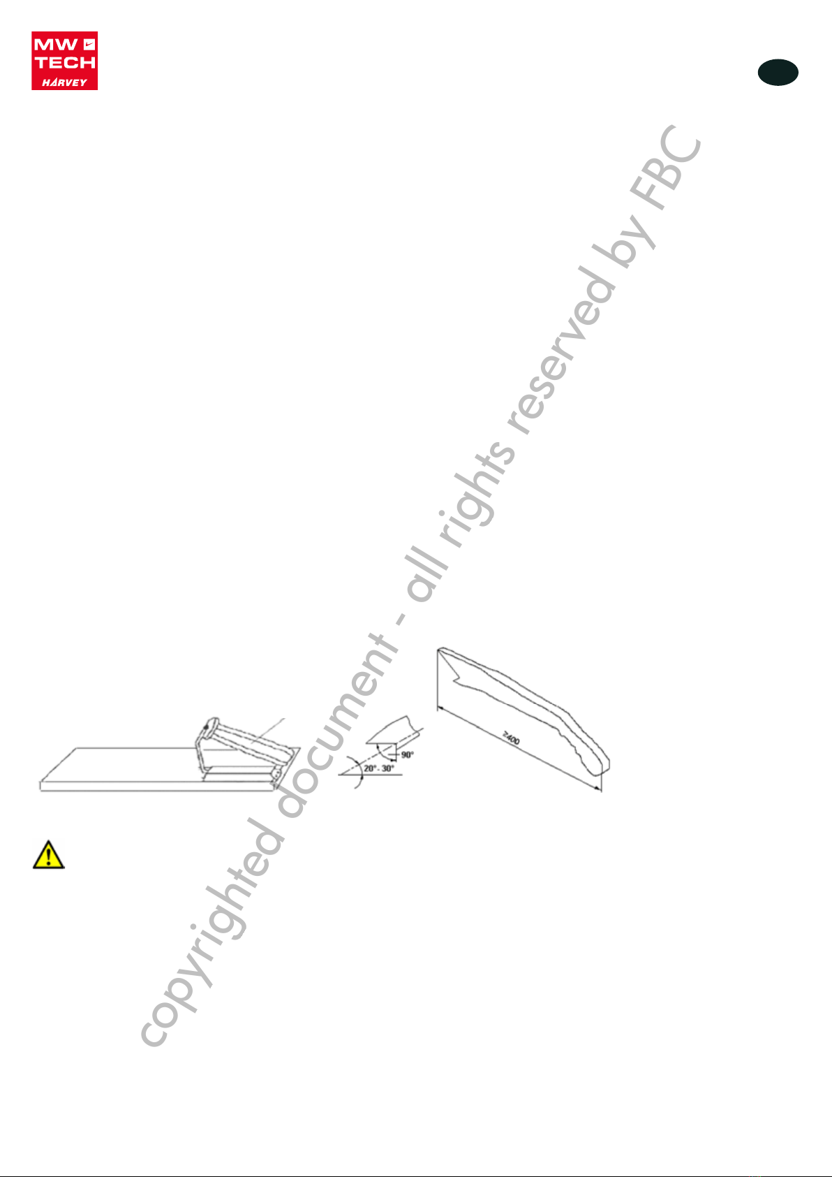
3. Het parallellisme van de langsgeleider controleren (guur 10)
• Schuif de langsgeleider langs de rail. Als hij op de tafel sleept, stel de voet aan de achterkant van de geleider in, om
deze net genoeg van de tafel op te tillen, zodat de ruimte tussen de geleider en de tafel van voren naar achteren gelijk is.
• Schuif de geleider naar boven tegen de rechterrand van de versteksleuf, en vergrendel deze op zijn plaats. Kijk hoe de
geleider met de versteksleuf uitgelijnd is.
OPMERKING
De achterkant van de langsgeleider kan maximum 1/64’’ gedraaid worden vanuit zijn positie
parallel aan het zaagblad� Hierdoor ontstaat er een iets grotere opening tussen de geleider en het
zaagblad aan de achterkant van het zaagblad, om het risico van vastlopen of verbranden van het
werkstuk te verminderen wanneer het ingevoerd wordt� Veel timmerlieden installeren bewust de
langsgeleider op die manier� Houd hier rekening mee bij het aanpassen van uw langsgeleider�
Montage van de schaal van de langsgeleider (guur 11)
• Schuif de langsgeleider tegen het zaagblad en vergrendel deze op zijn plaats.
• Bevestig het zelfklevende meetlint van de voorste rail boven de buis van de geleider door ervoor te zorgen dat deze
parallel is aan de buis en dat de 0 net onder de rode lijn op het pijlvenster is. Markeer de plaats van de 0 licht met een
pen op de buis van de geleider en verwijder vervolgens de langsgeleider. Verwijder het vel papier van het zelfklevende
meetlint en lijn de 0 op de schaal zorgvuldig met de penmarkering op de buis.
• Als u een fout maakt, draai dan de schroeven op het pijlvenster los, schuif de geleider tegen het zaagblad en pas het
venster met de pijl aan zodat de rode lijn onder de 0 komt op het meetlint. Draai de schroeven weer vast.
!
!
Langsgeleider
copyrighted document - all rights reserved by FBC

11
NL
M1.1.TZHD30S-50S.NLFREN - 15032019
make sure it is parallel with the tube, and the“0”
end is directly under the red line on the pointer
window as shown; lightly mark the “0”location on
the tube with a pencil, then remove the fence; peel
the tape and carefully align the “0”mark on the
scale with the pencil mark you made;
If you make a mistake, loosen the screws on the
point window, slide the fence against the blade,
adjust the pointer window, so the red line on the
window is over the “0”mark on the tape, then
secure the screws;
5.4.6 Install the switch
Install the magnetic switch onto the bottom left
hand side of the front rail. (Fig.12)
Fig.12 switch install
5.4.7 Install the blade
A. Remove table insert;
B. Rise the arbor all the way up and set the blade
angle at 0º;
C. Remove the arbor nut and arbor flange from the
arbor, slide on the included 10" saw blade, making
sure the teeth face the front of the saw, then install
the arbor flange and arbor nut onto the blade;
D. Put on a pair of heavy leather gloves and use
the included arbor wrenches to tighten the arbor
nut (turn clockwise to tighten), as shown in Fig.13
Fig.13 Install the blade
5.4.8 Install the blade guard
A. Reinstall the insert, slide the knurled knob out
(see Fig.14) and rotate it forward so it engages the
upper bracket.
Fig.14 Knurled knob used
B. slide the blade guard spreader all the way down
into the block, then rotate the knurled knob so it
disengages the bracket and the locking pin
engages the hole in the center of the spreader.
C. give the spreader an upward tug to verify that it
is locked the blade guard, when properly installed,
look like Fig, 15
Fig.15 Blade guard installed.
Check that saw blade clamping system is tight
before operating the machine.
Inzetstuk
Borgpen
Instelblok
Kartelknop
Houder
Figuur 14 Gebruik van de kartelknop
make sure it is parallel with the tube, and the“0”
end is directly under the red line on the pointer
window as shown; lightly mark the “0”location on
the tube with a pencil, then remove the fence; peel
the tape and carefully align the “0”mark on the
scale with the pencil mark you made;
If you make a mistake, loosen the screws on the
point window, slide the fence against the blade,
adjust the pointer window, so the red line on the
window is over the “0”mark on the tape, then
secure the screws;
5.4.6 Install the switch
Install the magnetic switch onto the bottom left
hand side of the front rail. (Fig.12)
Fig.12 switch install
5.4.7 Install the blade
A. Remove table insert;
B. Rise the arbor all the way up and set the blade
angle at 0º;
C. Remove the arbor nut and arbor flange from the
arbor, slide on the included 10" saw blade, making
sure the teeth face the front of the saw, then install
the arbor flange and arbor nut onto the blade;
D. Put on a pair of heavy leather gloves and use
the included arbor wrenches to tighten the arbor
nut (turn clockwise to tighten), as shown in Fig.13
Fig.13 Install the blade
5.4.8 Install the blade guard
A. Reinstall the insert, slide the knurled knob out
(see Fig.14) and rotate it forward so it engages the
upper bracket.
Fig.14 Knurled knob used
B. slide the blade guard spreader all the way down
into the block, then rotate the knurled knob so it
disengages the bracket and the locking pin
engages the hole in the center of the spreader.
C. give the spreader an upward tug to verify that it
is locked the blade guard, when properly installed,
look like Fig, 15
Fig.15 Blade guard installed.
Check that saw blade clamping system is tight
before operating the machine.
Figuur 13 Installatie van het zaagblad
make sure it is parallel with the tube, and the“0”
end is directly under the red line on the pointer
window as shown; lightly mark the “0”location on
the tube with a pencil, then remove the fence; peel
the tape and carefully align the “0”mark on the
scale with the pencil mark you made;
If you make a mistake, loosen the screws on the
point window, slide the fence against the blade,
adjust the pointer window, so the red line on the
window is over the “0”mark on the tape, then
secure the screws;
5.4.6 Install the switch
Install the magnetic switch onto the bottom left
hand side of the front rail. (Fig.12)
Fig.12 switch install
5.4.7 Install the blade
A. Remove table insert;
B. Rise the arbor all the way up and set the blade
angle at 0º;
C. Remove the arbor nut and arbor flange from the
arbor, slide on the included 10" saw blade, making
sure the teeth face the front of the saw, then install
the arbor flange and arbor nut onto the blade;
D. Put on a pair of heavy leather gloves and use
the included arbor wrenches to tighten the arbor
nut (turn clockwise to tighten), as shown in Fig.13
Fig.13 Install the blade
5.4.8 Install the blade guard
A. Reinstall the insert, slide the knurled knob out
(see Fig.14) and rotate it forward so it engages the
upper bracket.
Fig.14 Knurled knob used
B. slide the blade guard spreader all the way down
into the block, then rotate the knurled knob so it
disengages the bracket and the locking pin
engages the hole in the center of the spreader.
C. give the spreader an upward tug to verify that it
is locked the blade guard, when properly installed,
look like Fig, 15
Fig.15 Blade guard installed.
Check that saw blade clamping system is tight
before operating the machine.
Figuur 12 Installatie van de schakelaar
make sure it is parallel with the tube, and the“0”
end is directly under the red line on the pointer
window as shown; lightly mark the “0”location on
the tube with a pencil, then remove the fence; peel
the tape and carefully align the “0”mark on the
scale with the pencil mark you made;
If you make a mistake, loosen the screws on the
point window, slide the fence against the blade,
adjust the pointer window, so the red line on the
window is over the “0”mark on the tape, then
secure the screws;
5.4.6 Install the switch
Install the magnetic switch onto the bottom left
hand side of the front rail. (Fig.12)
Fig.12 switch install
5.4.7 Install the blade
A. Remove table insert;
B. Rise the arbor all the way up and set the blade
angle at 0º;
C. Remove the arbor nut and arbor flange from the
arbor, slide on the included 10" saw blade, making
sure the teeth face the front of the saw, then install
the arbor flange and arbor nut onto the blade;
D. Put on a pair of heavy leather gloves and use
the included arbor wrenches to tighten the arbor
nut (turn clockwise to tighten), as shown in Fig.13
Fig.13 Install the blade
5.4.8 Install the blade guard
A. Reinstall the insert, slide the knurled knob out
(see Fig.14) and rotate it forward so it engages the
upper bracket.
Fig.14 Knurled knob used
B. slide the blade guard spreader all the way down
into the block, then rotate the knurled knob so it
disengages the bracket and the locking pin
engages the hole in the center of the spreader.
C. give the spreader an upward tug to verify that it
is locked the blade guard, when properly installed,
look like Fig, 15
Fig.15 Blade guard installed.
Check that saw blade clamping system is tight
before operating the machine.
Figuur 15 Geïnstalleerde zaagbladbescherming
Installatie van de schakelaar
Monteer de magneetschakelaar links onder de voorste rail (guur 12).
Montage van het zaagblad
1. Verwijder het tafelinzetstuk.
2. Til de as volledig en stel de zaagbladhoek op 0°.
3. Verwijder de moer en de ens van de as en schuif deze op het meegeleverde 10’’ zaagblad, door ervoor te zorgen dat de
tanden naar de voorkant van de zaag gericht zijn. Plaats vervolgens de ens en de asmoer op het zaagblad.
4. Trek een paar dikke leren handschoenen aan et gebruik de meegeleverde sleutels om de asmoer aan te draaien (draai met
de klok mee om vast te draaien), zoals getoond op guur 13.
Montage van de zaagbladbescherming
1. Plaats het tafelinzetstuk terug, trek op de kartelknop (zie guur 14) en draai naar voren, zodat de knop in de bovenste
houder vastklikt.
2. Duw het spouwmes helemaal in het blok, draai vervolgens de kartelknop om de houder los te maken en de borgpen in het
middengat van het spouwmes vast te klikken.
3. Trek het spouwmes naar boven, om te controleren dat het goed in de zaagbladbescherming vergrendeld is. Als de
installatie juist is, moet het zoals op guur 15 verschijnen.
WAARSCHUWING!
Controleer voordat u de machine gebruikt, dat de zaagblad bevestiging goed vastzit�
copyrighted document - all rights reserved by FBC

12
NL
M1.1.TZHD30S-50S.NLFREN - 15032019
D. Place a straightedge against the blade and the
spreader. When properly aligned, the
spreader/riving knife will be in the "alignment
zone," shown in Fig.16, and will be parallel with the
blade.
Fig.16 alignment zone
After changing a saw blade, always check that the
Riving knife or Blade Guard is correctly set!
A. Riving knives shall be manufactured from steel
with an ultimate tensile strength of 580 N mm-2 or
of a comparable material, have flat sides (within
0,1 mm per 100 mm) and shall have a thickness
less than the width of cut (kerf) and at least 0,2mm
greater than the saw blade plate. As Fig.17
Fig.17
Key:
e riving knife thickness
b saw blade blade
B kerf(width of saw blade cut)
B. The distance of the riving knife from the gear rim
must be between 3mm and 8mm. measured
radially through the centre of the saw spindle. As
Fig.18
Fig.18
C. The highest point of the riving knife must be set
beneath the topmost teeth.
5.4.9 Extraction system
Dust collector device should be prepared by
customer.
The dust extraction equipment is to be
switched on before commencing machining.
The outlet diameter is 100mm. Fig.19
Air current speed is 20m/s for vacuum suction dust
emission index, when air current speed of dust
collector device (in accordance with EN
12779:2004) is not lower than 20m/s, ensure
machine can be normal exhausted.
1. Required air flow: 800 m3/h;
2. Ensure pressure drop of each dust collector
outlet carrying air current speed: 1100Pa
3. Dry chips: 20m/s.
4. Wet chips: 28m/s. (water content is equal
to18%)
Fig.19
Figuur 17
D. Place a straightedge against the blade and the
spreader. When properly aligned, the
spreader/riving knife will be in the "alignment
zone," shown in Fig.16, and will be parallel with the
blade.
Fig.16 alignment zone
After changing a saw blade, always check that the
Riving knife or Blade Guard is correctly set!
A. Riving knives shall be manufactured from steel
with an ultimate tensile strength of 580 N mm-2 or
of a comparable material, have flat sides (within
0,1 mm per 100 mm) and shall have a thickness
less than the width of cut (kerf) and at least 0,2mm
greater than the saw blade plate. As Fig.17
Fig.17
Key:
e riving knife thickness
b saw blade blade
B kerf(width of saw blade cut)
B. The distance of the riving knife from the gear rim
must be between 3mm and 8mm. measured
radially through the centre of the saw spindle. As
Fig.18
Fig.18
C. The highest point of the riving knife must be set
beneath the topmost teeth.
5.4.9 Extraction system
Dust collector device should be prepared by
customer.
The dust extraction equipment is to be
switched on before commencing machining.
The outlet diameter is 100mm. Fig.19
Air current speed is 20m/s for vacuum suction dust
emission index, when air current speed of dust
collector device (in accordance with EN
12779:2004) is not lower than 20m/s, ensure
machine can be normal exhausted.
1. Required air flow: 800 m3/h;
2. Ensure pressure drop of each dust collector
outlet carrying air current speed: 1100Pa
3. Dry chips: 20m/s.
4. Wet chips: 28m/s. (water content is equal
to18%)
Fig.19
Figuur 18
!
!
D. Place a straightedge against the blade and the
spreader. When properly aligned, the
spreader/riving knife will be in the "alignment
zone," shown in Fig.16, and will be parallel with the
blade.
Fig.16 alignment zone
After changing a saw blade, always check that the
Riving knife or Blade Guard is correctly set!
A. Riving knives shall be manufactured from steel
with an ultimate tensile strength of 580 N mm-2 or
of a comparable material, have flat sides (within
0,1 mm per 100 mm) and shall have a thickness
less than the width of cut (kerf) and at least 0,2mm
greater than the saw blade plate. As Fig.17
Fig.17
Key:
e riving knife thickness
b saw blade blade
B kerf(width of saw blade cut)
B. The distance of the riving knife from the gear rim
must be between 3mm and 8mm. measured
radially through the centre of the saw spindle. As
Fig.18
Fig.18
C. The highest point of the riving knife must be set
beneath the topmost teeth.
5.4.9 Extraction system
Dust collector device should be prepared by
customer.
The dust extraction equipment is to be
switched on before commencing machining.
The outlet diameter is 100mm. Fig.19
Air current speed is 20m/s for vacuum suction dust
emission index, when air current speed of dust
collector device (in accordance with EN
12779:2004) is not lower than 20m/s, ensure
machine can be normal exhausted.
1. Required air flow: 800 m3/h;
2. Ensure pressure drop of each dust collector
outlet carrying air current speed: 1100Pa
3. Dry chips: 20m/s.
4. Wet chips: 28m/s. (water content is equal
to18%)
Fig.19
Figuur 16 Uitlijningszone
Zaagblad
Spouwmes
Uitlijnings-
zone
D. Place a straightedge against the blade and the
spreader. When properly aligned, the
spreader/riving knife will be in the "alignment
zone," shown in Fig.16, and will be parallel with the
blade.
Fig.16 alignment zone
After changing a saw blade, always check that the
Riving knife or Blade Guard is correctly set!
A. Riving knives shall be manufactured from steel
with an ultimate tensile strength of 580 N mm-2 or
of a comparable material, have flat sides (within
0,1 mm per 100 mm) and shall have a thickness
less than the width of cut (kerf) and at least 0,2mm
greater than the saw blade plate. As Fig.17
Fig.17
Key:
e riving knife thickness
b saw blade blade
B kerf(width of saw blade cut)
B. The distance of the riving knife from the gear rim
must be between 3mm and 8mm. measured
radially through the centre of the saw spindle. As
Fig.18
Fig.18
C. The highest point of the riving knife must be set
beneath the topmost teeth.
5.4.9 Extraction system
Dust collector device should be prepared by
customer.
The dust extraction equipment is to be
switched on before commencing machining.
The outlet diameter is 100mm. Fig.19
Air current speed is 20m/s for vacuum suction dust
emission index, when air current speed of dust
collector device (in accordance with EN
12779:2004) is not lower than 20m/s, ensure
machine can be normal exhausted.
1. Required air flow: 800 m3/h;
2. Ensure pressure drop of each dust collector
outlet carrying air current speed: 1100Pa
3. Dry chips: 20m/s.
4. Wet chips: 28m/s. (water content is equal
to18%)
Fig.19
Figuur 19
Stofzuig-
mond
(100 mm)
4. Plaats een liniaal tegen het zaagblad en het spouwmes. Als de uitlijning juist is, zal het spouwmes zich in de
uitlijningszone bevinden, zoals getoond op guur 16, en parallel met het zaagblad zijn.
OPMERKING
Controleer altijd na het vervangen van het zaagblad, dat het spouwmes of de
zaagbladbescherming correct ingesteld is�
1. Spouwmessen moeten gemaakt zijn van staal met een maximale treksterkte van 580 N/mm² of gelijkaardig materiaal,
vlakke kanten hebben (binnen de grens van 0,1 mm per 100 mm) en een dikte die kleiner is dan de snijbreedte
(insnijding) en groter van minstens 0,2 mm dan deze van het zaagblad (guur 17).
2. De afstand tussen het spouwmes en het tandwiel moet tussen 3 en 8 mm liggen, gemeten door het midden van de zaagas
(guur 18).
3. Het hoogste punt van het spouwmes moet onder de boventanden ingesteld worden.
Afzuigsysteem
OPMERKING
De gebruiker moet een stofafzuigsysteem installeren�
De stofzuiger moet voor het begin van de bewerking ingeschakeld worden�
De uitlaatdiameter is 100 mm (guur 19).
De luchtstroomsnelheid is 20 m/s voor de zuigstofemissie. Wanneer de luchtstroomsnelheid van de stofzuiger(conform
EN 12779:2004) niet lager is dan 20 m/s, zorg ervoor dat de machine normaal afgezogen kan worden.
1. Vereist luchtdebiet: 800 m³/h.
2. Zorg voor het drukverlies van elke stofzuiger die de luchtstroomsnelheid draagt: 1100 Pa.
3. Droge spanen: 20 m/s
4. Vochtige spanen: 28 m/s (watergehalte gelijk aan 18%)
copyrighted document - all rights reserved by FBC

13
NL
M1.1.TZHD30S-50S.NLFREN - 15032019
5.4.10 Electrical installation
Wiring should only be done by professional
electricians. Always make sure the machine is
properly earthed.
All wirings in the cabinets should be protected
against direct contact to at least IP2X when
finishing electrical installation.
All exposed conductive parts should be
connected to the protective bonding circuit.
Close and lock the door of cabinets。
Enough space around the machine and the
cabinets should be kept in order to maintain
conveniently.
The machine should be installed in a workshop
with good illumination and ventilation.
Over-voltage protection device should be
provided by end user on spot.
Check that the voltage and frequency required by
the machine, shown on the machine’s name plate,
correspond to the electric power supply voltage
and frequency.
The circuit breaker shall be installed for supplying
electric power to this machine, in order to protect
people against electrical shock due to indirect
shock
Wiring:
Finish electrical connection according to the
electrical drawings.
The wirings on the spot should refer to the
requirements of Clause 13 (Wring practices) of EN
60204-1:2006.
Checking:
After finishing wiring on the spot, check the
following items at least:
Check the wirings of machine.
Check the direction of motors and change wiring if
necessary.
Check the components for defects, such as
loosening or damage.
Check the functions of safety d
ELECTRICAL CONNECTIONS
Elektrische installatie
WAARSCHUWING!
• De bekabeling moet door professionele elektriciens uitgevoerd worden� Zorg er altijd voor dat
de machine correct geaard is�
• De bekabeling in de machine moeten na het einde van de elektrische installatie tegen een
direct contact beschermd worden met een beschermingsgraad van minstens IP2X�
• Alle blootgestelde geleidenden delen moeten op het aardingscircuit aangesloten worden�
• Sluit en vergrendel de deur van de kasten�
OPMERKING
• Een voldoende ruimte moet rond de machine en de kasten vrij gehouden worden, om het
onderhoud ervan te vergemakkelijken�
• De machine moet in een goed verlichte en geventileerde werkplaats geïnstalleerd worden�
• De overbelastingsbeveiliging moet door de gebruiker ter plaatse aangebracht worden�
Controleer dat de door de machine vereiste spanning en frequentie, die op de naamplaat vermeld zijn, met de spanning en
frequentie van de stroomvoeding overeenstemmen.
Een stroomonderbreker moet op de stroomvoeding geïnstalleerd worden, om mensen te beschermen tegen elektrische schokken
als gevolg van indirecte schokken.
Bekabeling:
Voer de elektrische aansluitingen uit volgens de schakelschema’s.
De bekabeling ter plaatse moet voldoen aan de eisen van punt 13 (bedradingspraktijken) van de norm EN 60204-1:2006).
Controle:
Controleer na voltooiing van de bekabeling ter plaatse ten minste de volgende punten:
• Controleer de bekabeling van de machine.
• Controleer de draairichting van de motor en wijzig de bekabeling indien nodig.
• Controleer of componenten defect, los of beschadigd zijn.
• Controleer de werking van de veiligheidsvoorzieningen.
!
copyrighted document - all rights reserved by FBC

14
NL
M1.1.TZHD30S-50S.NLFREN - 15032019
6. Adjustment
Before operation, the machine should be
carefully adjusted for best performance. Please
make adjustment as following:
6.1 Blade Raising and Tilting Machine
To raise or lower the blade, loosen lock knob (C)
As Fig.20 and turn the raising hand wheel (D).
When desired height is obtained, retighten lock
knob. The blade should be raised 1/8” to 1/4”
above the top surface of the material being cut.
With hollow ground blades the blade should be
raised to the maximum to provide chip clearance.
To tilt the saw blade, loosen lock knob (B) and turn
tilting hand wheel (A). When desired angle is
obtained, retighten lock knob. See Fig.20.
Fig.20
6.2 Adjusting Rip fence
1. The rip fence must be perfectly aligned with the
table T-slot, to verify this, align the edge of the rip
fence with the table T-slot and lower the locking
lever (A) Fig.21 to lock in into place. Check to see
if the edge of the rip fence and the table T-slot are
parallel. If they are not parallel, unlock the rip fence
and turn it upside down. Adjust the set screws (H)
as Fig.22in or out, verify your adjustment, repeat if
necessary.
2. The lock lever pressure can be adjusted by
loosening the front lock nuts (B) as Fig.21 and
adjusting the set screws (C) the same amount,
make sure the fence remains parallel with the table
T-slot. Retighten lock nuts.
3. To set the fence perpendicular to the table, place
a square on the table and against the side of the
fence, loosen the top lock nuts (D) and adjust the
setscrews (E) until the fence is perpendicular.
Retighten lock nuts.
4. The pointer window (F) as Fig.21 position can
be adjusted if needed, loosen pan head screws (G),
reposition the pointer window and retighten pan
head screws.
Fig.21
Fig.22
6.3 Aligning Table T-slot Parallel with Blade
1, The table T-slot must be aligned parallel with the
blade. Using a combination square measure the
distance from the back edge of the blade to the
table T-slot. Pivot blade forward 180º and
re-measure the distance using the exact same
point on the blade. The difference between both
measurements must be less than 0.2mm. (Fig.23)
Figuur 21
6. Adjustment
Before operation, the machine should be
carefully adjusted for best performance. Please
make adjustment as following:
6.1 Blade Raising and Tilting Machine
To raise or lower the blade, loosen lock knob (C)
As Fig.20 and turn the raising hand wheel (D).
When desired height is obtained, retighten lock
knob. The blade should be raised 1/8” to 1/4”
above the top surface of the material being cut.
With hollow ground blades the blade should be
raised to the maximum to provide chip clearance.
To tilt the saw blade, loosen lock knob (B) and turn
tilting hand wheel (A). When desired angle is
obtained, retighten lock knob. See Fig.20.
Fig.20
6.2 Adjusting Rip fence
1. The rip fence must be perfectly aligned with the
table T-slot, to verify this, align the edge of the rip
fence with the table T-slot and lower the locking
lever (A) Fig.21 to lock in into place. Check to see
if the edge of the rip fence and the table T-slot are
parallel. If they are not parallel, unlock the rip fence
and turn it upside down. Adjust the set screws (H)
as Fig.22in or out, verify your adjustment, repeat if
necessary.
2. The lock lever pressure can be adjusted by
loosening the front lock nuts (B) as Fig.21 and
adjusting the set screws (C) the same amount,
make sure the fence remains parallel with the table
T-slot. Retighten lock nuts.
3. To set the fence perpendicular to the table, place
a square on the table and against the side of the
fence, loosen the top lock nuts (D) and adjust the
setscrews (E) until the fence is perpendicular.
Retighten lock nuts.
4. The pointer window (F) as Fig.21 position can
be adjusted if needed, loosen pan head screws (G),
reposition the pointer window and retighten pan
head screws.
Fig.21
Fig.22
6.3 Aligning Table T-slot Parallel with Blade
1, The table T-slot must be aligned parallel with the
blade. Using a combination square measure the
distance from the back edge of the blade to the
table T-slot. Pivot blade forward 180º and
re-measure the distance using the exact same
point on the blade. The difference between both
measurements must be less than 0.2mm. (Fig.23)
Figuur 22
6. Adjustment
Before operation, the machine should be
carefully adjusted for best performance. Please
make adjustment as following:
6.1 Blade Raising and Tilting Machine
To raise or lower the blade, loosen lock knob (C)
As Fig.20 and turn the raising hand wheel (D).
When desired height is obtained, retighten lock
knob. The blade should be raised 1/8” to 1/4”
above the top surface of the material being cut.
With hollow ground blades the blade should be
raised to the maximum to provide chip clearance.
To tilt the saw blade, loosen lock knob (B) and turn
tilting hand wheel (A). When desired angle is
obtained, retighten lock knob. See Fig.20.
Fig.20
6.2 Adjusting Rip fence
1. The rip fence must be perfectly aligned with the
table T-slot, to verify this, align the edge of the rip
fence with the table T-slot and lower the locking
lever (A) Fig.21 to lock in into place. Check to see
if the edge of the rip fence and the table T-slot are
parallel. If they are not parallel, unlock the rip fence
and turn it upside down. Adjust the set screws (H)
as Fig.22in or out, verify your adjustment, repeat if
necessary.
2. The lock lever pressure can be adjusted by
loosening the front lock nuts (B) as Fig.21 and
adjusting the set screws (C) the same amount,
make sure the fence remains parallel with the table
T-slot. Retighten lock nuts.
3. To set the fence perpendicular to the table, place
a square on the table and against the side of the
fence, loosen the top lock nuts (D) and adjust the
setscrews (E) until the fence is perpendicular.
Retighten lock nuts.
4. The pointer window (F) as Fig.21 position can
be adjusted if needed, loosen pan head screws (G),
reposition the pointer window and retighten pan
head screws.
Fig.21
Fig.22
6.3 Aligning Table T-slot Parallel with Blade
1, The table T-slot must be aligned parallel with the
blade. Using a combination square measure the
distance from the back edge of the blade to the
table T-slot. Pivot blade forward 180º and
re-measure the distance using the exact same
point on the blade. The difference between both
measurements must be less than 0.2mm. (Fig.23)
Figuur 20
4 Instellingen
OPMERKING
De machine moet voor gebruik zorgvuldig ingesteld worden, om de beste prestaties te leveren�
Maak de volgende instellingen:
De hoogte en de helling van het zaagblad instellen
Om het zaagblad omhoog of omlaag te brengen, draai de vergrendelingsknop (C) los zoals op guur 20 en draai het
handwiel (D). Draai de vergrendelingsknop weer aan wanneer de gewenste hoogte bereikt wordt. Het zaagblad moet zich
tussen 1/8” en 1/4” boven het bovenvlak van het te snijden werkstuk bevinden. Bij geslepen holle zaagbladen, moet het
zaagblad tot het maximum geheven worden, om de afvoer van de spanen te waarborgen. Om het zaagblad te kantelen, draai
de vergrendelingsknop (B) los en draai het handwiel (A). Draai de vergrendelingsknop weer aan wanneer de gewenste helling
bereikt wordt. Zie guur 20.
Instelling van de langsgeleider
1. De langsgeleider moet perfect uitgelijnd zijn met de T-sleuf van de tafel. Om te controleren, lijn de rand van de geleider
met de V-sleuf uit en breng de klemhendel (A) omlaag (zie guur 2) om deze op zijn plaats te houden. Controleer of de
rand van de geleider en de sleuf parallel zijn. Als ze niet parallel zijn, ontgrendel de geleider en draai deze om. Pas de
stelschroeven (H) (zie guur 22) naar binnen of naar buiten aan, controleer de instelling en herhaal indien nodig.
2. De druk van de klemhendel kan aangepast worden door de voorste borgmoer (B) los te draaien, zoals op guur 21
getoond en door de stelschroeven (C) gelijk aan te passen. Maak zeker dat de langsgeleider parallel blijft met de T-sleuf
van de tafel. Draai de borgmoer weer aan.
3. Om de langsgeleider loodrecht op de tafel af te stellen, plaats een winkelheek op de tafel tegen de zijkant van de geleider,
draai de bovenste borgmoer (D) en stel de stelschroeven (E) af totdat de langsgeleider loodrecht is. Draai de borgmoer
weer aan.
4. De positie van het venster van de pijl (F) (zie guur 21) kan indien nodig afgesteld worden. Draai de schroeven (G) los,
positioneer het venster van de pijl en draai de schroeven weer aan.
!
copyrighted document - all rights reserved by FBC

15
NL
M1.1.TZHD30S-50S.NLFREN - 15032019
Parallellisme van de T-sleuf van de tafel met het zaagblad
1. De T-sleuf van de tafel moet parallel zijn met het zaagblad. Gebruik een combinatiewinkelhaak om de afstand tussen de
achterste rand van het zaagblad en de T-sleuf. Draai het zaagblad 180° naar voren en meet opnieuw de afstand vanaf
hetzelfde punt op het zaagblad. Het verschil tussen beide metingen moet kleiner zijn dan 0,2 mm (guur 23).
2. Als een afstelling noodzakelijk is, draai de schroeven los, die als pijlpunten dienen en die op de tafel bevestigd worden,
voer de nodige afstelling uit totdat beide metingen gelijk zijn aan of kleiner dan 0,2 mm en draai de schroeven weer aan
(guur 24).
Instelling van de positieve 45° en 90° aanslagen
Het kantelmechanisme heeft aanslagen voor de verticale (90°) en 45° positie. De machine is in de fabriek ingesteld, maar als
een afstelling noodzakelijk is, draai de borgmoer los, stel de aanslagschroef af en draai de borgmoer weer aan. Zie guur 25.
Uitlijning van het spouwmes met het zaagblad
Het spouwmes moet met het zaagblad uitgelijnd zijn. Als het niet correct uitgelijnd is, zal het spouwmes tijdens het snijden
zijdelings op het werkstuk duwen, waardoor de kans op terugslag toeneemt. Plaats een liniaal tegen het zaagblad en het
spouwmes en controleer het parallellisme. Als een afstelling noodzakelijk is, kunt u de positie verbeteren door middel van de
stelschroeven (A) (guur 26).
1. Koppel de machine los van de stroomtoevoer.
2. Verwijder het tafelinzetstuk.
3. Draai de bovenste en onderste schroeven (B), pas de 4 stelschroeven naar binnen of naar buiten aan, totdat de uitlijning
perfect parallel is.
4. Zet het tafelinzetstuk weer op zijn plaats.
2. If an adjustment is necessary, loosen the screws
as arrow point which fix to the table, make the
needed adjustment until both measurements are
equal or less than 0.2mm. and retighten the screws.
(Fig.24)
Fig.23
Fig.24
6.4 Adjusting 45°and 90°Positive Stops
The tilt mechanism has adjustable stops for vertical
and 45 degrees. the machine comes factory-set but
should adjustment be required, loose the lock nut,
adjust the stop screw and retighten the lock nut.
See Fig.25
Fig.25 Adjust 90&45 degrees
6.5 Aligning Blade Guard Splitter or Riving
Knife with Blade
The blade guard splitter and/or riving knife must be
aligned with the blade. If not properly aligned, the
splitter/riving knife will force the workpiece
sideways
during the cut, increasing risk of kickback. Place a
straightedge against the blade and the splitter or
riving knife and check for parallelism. If an
adjustment is needed, the mounting position can
be adjusted into alignment with the blade using the
adjustment set screws (A) (see Fig.26)
1. Disconect saw from power source.
2. Remove the table insert.
3. Loosen the upper and lower cap screws (B),
then adjust the 4 set screws in or out until the
alignement is perfectly parallel.
4. Reinstall the table insert.
Fig.26
Figuur 25 90° en 45° instelling
Aanslagen
2. If an adjustment is necessary, loosen the screws
as arrow point which fix to the table, make the
needed adjustment until both measurements are
equal or less than 0.2mm. and retighten the screws.
(Fig.24)
Fig.23
Fig.24
6.4 Adjusting 45°and 90°Positive Stops
The tilt mechanism has adjustable stops for vertical
and 45 degrees. the machine comes factory-set but
should adjustment be required, loose the lock nut,
adjust the stop screw and retighten the lock nut.
See Fig.25
Fig.25 Adjust 90&45 degrees
6.5 Aligning Blade Guard Splitter or Riving
Knife with Blade
The blade guard splitter and/or riving knife must be
aligned with the blade. If not properly aligned, the
splitter/riving knife will force the workpiece
sideways
during the cut, increasing risk of kickback. Place a
straightedge against the blade and the splitter or
riving knife and check for parallelism. If an
adjustment is needed, the mounting position can
be adjusted into alignment with the blade using the
adjustment set screws (A) (see Fig.26)
1. Disconect saw from power source.
2. Remove the table insert.
3. Loosen the upper and lower cap screws (B),
then adjust the 4 set screws in or out until the
alignement is perfectly parallel.
4. Reinstall the table insert.
Fig.26
Figuur 24
2. If an adjustment is necessary, loosen the screws
as arrow point which fix to the table, make the
needed adjustment until both measurements are
equal or less than 0.2mm. and retighten the screws.
(Fig.24)
Fig.23
Fig.24
6.4 Adjusting 45°and 90°Positive Stops
The tilt mechanism has adjustable stops for vertical
and 45 degrees. the machine comes factory-set but
should adjustment be required, loose the lock nut,
adjust the stop screw and retighten the lock nut.
See Fig.25
Fig.25 Adjust 90&45 degrees
6.5 Aligning Blade Guard Splitter or Riving
Knife with Blade
The blade guard splitter and/or riving knife must be
aligned with the blade. If not properly aligned, the
splitter/riving knife will force the workpiece
sideways
during the cut, increasing risk of kickback. Place a
straightedge against the blade and the splitter or
riving knife and check for parallelism. If an
adjustment is needed, the mounting position can
be adjusted into alignment with the blade using the
adjustment set screws (A) (see Fig.26)
1. Disconect saw from power source.
2. Remove the table insert.
3. Loosen the upper and lower cap screws (B),
then adjust the 4 set screws in or out until the
alignement is perfectly parallel.
4. Reinstall the table insert.
Fig.26
Figuur 26
2. If an adjustment is necessary, loosen the screws
as arrow point which fix to the table, make the
needed adjustment until both measurements are
equal or less than 0.2mm. and retighten the screws.
(Fig.24)
Fig.23
Fig.24
6.4 Adjusting 45°and 90°Positive Stops
The tilt mechanism has adjustable stops for vertical
and 45 degrees. the machine comes factory-set but
should adjustment be required, loose the lock nut,
adjust the stop screw and retighten the lock nut.
See Fig.25
Fig.25 Adjust 90&45 degrees
6.5 Aligning Blade Guard Splitter or Riving
Knife with Blade
The blade guard splitter and/or riving knife must be
aligned with the blade. If not properly aligned, the
splitter/riving knife will force the workpiece
sideways
during the cut, increasing risk of kickback. Place a
straightedge against the blade and the splitter or
riving knife and check for parallelism. If an
adjustment is needed, the mounting position can
be adjusted into alignment with the blade using the
adjustment set screws (A) (see Fig.26)
1. Disconect saw from power source.
2. Remove the table insert.
3. Loosen the upper and lower cap screws (B),
then adjust the 4 set screws in or out until the
alignement is perfectly parallel.
4. Reinstall the table insert.
Fig.26
Figuur 23
T-sleuf
copyrighted document - all rights reserved by FBC

16
NL
M1.1.TZHD30S-50S.NLFREN - 15032019
7. Operations
7.1 Electrical Operation (Fig.27)
ON Button: Starts the motor.
Hole for safety pin: When installed pin, disables
the ON Button to prevent accidental startup.
STOP Button: Turns machine.
Fig.27
7.2 Safety Precautions before Operations
The operation of power tools involves a certain
amount of hazard for the operator. Before
attempting regular work we recommend you get
the feel of operations using scrap lumber to check
settings. Read entire instructions before you start
to cut workpiece. Always pay attention to safety
precautions to avoid personal injury.
7.3 Operation
Plain sawing includes ripping and crosscutting,
plus a few other standard operations of a
fundamental nature. The following methods feature
safety. As with all power tools there is a certain
amount of hazard involved with the operation and
use of the tool. Using the tool with the respect and
caution demanded as far as safety precautions are
concerned will considerably lessen the possibility
of personal injury. However, if normal safety
precautions are overlooked or completely ignored,
personal injury to the operator can develop. It is
good practice to make trial cuts using scrap
material when setting up you saw for operation.
7.4 Crosscutting
Crosscutting requires the use of the miter gauge to
position and guide the work. Place the work
against the miter gauge and advance both the
miter gauge and work toward the saw blade.The
miter gauge may be used in either table slot,
however, most operators prefer the left groove for
average work. When bevel cutting (blade tilted),
use the table groove that does not cause
interference of your hand or miter gauge with the
saw blade guard.
Start the cut slowly and hold the work firmly against
the miter gauge and the table. One of the rules in
running a saw is that you never hang onto or touch
a free piece of work. Hold the supported piece, not
the free piece that is cut off. The feed in
crosscutting continues until the work is cut in two,
then the miter gauge and work are pulled back to
the starting point. Before pulling the work back it is
good practice to give the work a little sideways shift
to move the work slightly away from the saw blade.
Never pick up any short length of free work from
the table while the saw is running. A smart operator
never touches a cut-off piece unless it is at least a
foot long. Never use the fence as a cut-off gauge
when crosscutting. Never use the miter gauge in
combination with the rip fence.
7.5 Ripping
Ripping is the operation of making a lengthwise cut
through a board, and the rip fence is used to
position and guide the work. One edge of the work
rides against the rip fence while the flat side of the
board rest on the table. Since the work is pushed
along the fence, it must have a straight edge and
make solid contact with the table. The saw guard
must be used. The guard has anti-kickback fingers
and a splitter to prevent the saw kerf from closing.
Start the motor and advance the work holding it
down and against the fence. Never, stand in the
line of the saw cut when ripping. Hold the work with
both hands and push it along the fence and into the
saw blade as shown in Fig. The work can then be
fed through the saw blade with one or two hands.
When this is done the work will either stay on the
table, tilt up slightly and be caught by the rear end
of the guard or slide off the table to the floor.
Alternately, the feed can continue to the end of the
table, after which the work is lifted and brought
back along the outside edge of the fence. The
waste stock remains on the table and is not
touched with the hands until the saw is stopped
unless it is a large piece allowing safe removal.
ON knop
STOP
knop
Gat voor
veiligheids-
pen
Figuur 27
5 Bediening
5�1 Elektriciteit
Zie guur 27:
Startknop (ON): Om de motor te starten.
Gat voor de veiligheidspen: Wanneer de pen geïnstalleerd is,
deactiveert de startknop (ON) om een onbevoegd opstarten te voorkomen.
STOP knop : Om de machine uit te schakelen.
5�2 Voorzorgmaatregelen voor gebruik
Het gebruik van elektrische gereedschappen brengt een aantal risico’s met zich mee voor de bediener. Voordat u regelmatig
probeert te werken, raden wij u aan de machine te leren kennen door de instellingen te controleren met behulp van sloophout.
Lees de instructies volledig door voordat u begint te werken. Neem altijd de veiligheidsvoorschriften in acht om letsels te
voorkomen.
5�3 Bediening
Eenvoudige zaagwerkzaamheden omvatten langs- en dwarssnijden en enkele standaard bewerkingen. De volgende
methoden zijn veilig. Zoals met alle elektrische gereedschappen zijn er een aantal risico’s verbonden aan het gebruik van
uw machine. Als u de instructies en veiligheidsvoorschriften navolgt, wordt het letselsgevaar aanzienlijk verminderd. Als
de veiligheidsvoorschriften genegeerd worden, kan de gebruiker ernstig verwond raken. Het is een goede gewoonte om
proefzagen te maken met sloophout wanneer u de machine voor gebruik voorbereidt.
5�4 Dwarssnijden
Voor dwarssnijden is het gebruik van de verstekgeleider nodig om het werkstuk te plaatsen en te geleiden. Plaats het werkstuk
tegen het verstekgeleider en beweeg de geleider en het werkstuk naar het zaagblad toe. De verstekgeleider kan in de ene of
andere versteksleuf gebruikt worden. De meeste bedieners geven echter de voorkeur aan de linker sleuf voor gewoon werk.
Gebruik bij schuin snijden (hellend zaagblad) de versteksleuf die uw hand niet zal hinderen of de verstekgeleider met de
zaagbladbescherming.
Begin langzaam te zagen en houd het werkstuk stevig vast tegen de verstekgeleider en de tafel. Een van de regels bij het
gebruik van een zaagmachine is om het te zagen werkstuk nooit aan te raken. Houd het deel van het werkstuk dat ondersteund
wordt vast, niet het deel dat gesneden moet worden. De toevoer van het werkstuk gaat door totdat het in tweeën gesneden
wordt. Daarna worden de verstekgeleider en het werkstuk tot hun startpunt gebracht. Voordat u het werkstuk terugtrekt, is het
raadzaam het licht zijwaarts te verplaatsen, om het van het zaagblad af te bewegen.
Neem nooit een kort stuk van de tafel weg terwijl de zaag draait. Een slimme bediener raakt een afgesneden werkstuik
nooit aan als het minder dan een voet lang is. Gebruik de geleider nooit als langsaanslag voor dwarssnijden. Gebruik de
verstekgeleider nooit in combinatie met de langsgeleider.
5�5 Langssnijden
Langssnijden bestaat uit het zagen van een werkstuk over de gehele lengte, en de langsgeleider wordt gebruikt om het werkstuk
te plaatsen en te geleiden. Een rand van de plank beweegt tegen de langsgeleider, terwijl de platte kant van de plank tegen
de tafel ligt. Omdat het werkstuk langs de geleider geduwd wordt, moet het een rechte rand hebben en stevig in contact met de
tafel staan. De zaagbladbescherming moet gebruikt worden. Deze bescherming heeft anti-terugslagpennen en een spouwmes,
om te voorkomen dat de zaagsnede zich sluit.
Start de motor en voer het werkstuk toe door het tegen de tafel en de langsgeleider vast te houden. Blijf nooit in de snijlijn
staan. Houd het werkstuk met beide handen vast en duw het langs de geleider en naar het zaagblad toe. Het werkstuk kan
dan naar het zaagblad met een van beide handen geleid worden.
copyrighted document - all rights reserved by FBC

17
NL
M1.1.TZHD30S-50S.NLFREN - 15032019
8. Maintenance
This table saw requires very little maintenance
other than minor lubrication and cleaning. The
following sections detail what will need to be done
in order to assure continued operation of your saw.
LUBRICATION
The table saw has sealed lubricated bearings in
the motor housing and the arbor assembly, they
will not require any additional lubrication. Use a
wire brush to clean off the worm gears and
trunnions and apply a white lithium grease to keep
them lubricated
CLEANING
Cleaning the Model is relatively easy. Vacuum
excess wood chips and sawdust, and wipe off the
remaining dust with a dry cloth. If any resin has
built up, use a resin dissolving cleaner to remove it.
After cleaning, treat all unpainted cast iron and
steel with a non-staining lubricant.
Occasionally it will become necessary to clean the
internal parts with more than a vacuum. To do this,
remove the table top and clean the internal parts
with resin/pitch dissolver or mineral spirits and a
stiff wire brush or steel wool.
Make sure the internal workings are dry before
using the saw again, so that wood dust will not
accumulate. If any essential lubrication is removed
during cleaning, re-lubricate those areas.
CHANGING BELTS
WARNING: MAKE SURE THE POWER CORD IS
DISCONNECTED FROM THE POWER SOURCE!
1. Lower the blade completely, then open the
motor cover (right side), remove the window cover
(left side), see Fig.28.
2. Loosen the hex nuts A that secure the motor and
raise the motor fully to remove tension on the
V-belts. Roll the V-belts off of the arbor and motor
pulleys.
3. While continuing to raise the motor, install a new
matching set of V-belts onto the pulleys, lower the
motor to tension the V-belts, then tighten the hex
nuts.
4. Close the motor cover and window cover.
Fig.28
Zeskant-
moeren
Figuur 28
6 Onderhoud
Deze tafelcirkelzaag vereist heel weinig onderhoud, met uitzondering
van een minimale smering en reiniging. Le volgende paragrafen
beschrijven wat u moet doen om een continue werking van uw machine
te garanderen.
Smering
De tafelzaag heeft afgedichte gesmeerde lagers in de motorkap en
despindel, die geen extra smering nodig hebben.
Gebruik een staalborstel om de wormwielen en astap te reinigen, en
breng wit lithiumvet aan om deze gesmeerd te houden.
Reiniging
De reiniging van de machine is vrij gemakkelijk. Stofzuig houtspanen en
zaagstof, en verwijder het resterende stof met een droge doek af. Als de
hars vast blijft zitten, verwijder deze dan met een reiniger die de hars oplost.
Behandel de ongeverfde gietijzeren onderdelen na de reiniging met een niet-vlekkend smeermiddel.
Soms zal het nodig zijn om de binnenkant van de machine beter te reinigen dan met een stofzuiger. Verwijder hiervoor het
bovenblad van de tafel en reinig de binnenste onderdelen met een harssolvent of minerale alcohol en een staalborstel of
staalwol.
Zorg ervoor dat de binnenste onderdelen droog zijn voordat u de machine weer in bedrijf stelt, om de ophoping van houtstof
te voorkomen. Als er tijdens de reiniging smeermiddel verwijderd werd, smeer dan waar nodig opnieuw.
De riemen vervangen
WAARSCHUWING!
Maak zeker dat de machine losgekoppeld is van de stroomtoevoer!
1. Breng het zaagblad volledig omlaag en open vervolgens de motorkap (rechterkant). Verwijder het transparante deksel (zie
guur 28).
2. Draai de zeskantmoeren A los, die de motor bevestigen en til de motor volledig op, om de V-riemen te ontspannen.
Verwijder de riemen van de as en katrollen.
3. Terwijl u de motor blijft optillen, installeer de nieuwe set V-riemen. Laat vervolgens de motor zakken om de riemen te
spannen, en draai de zeskantmoeren weer aan.
4. Sluit de motor kap en het transparante deksel.
Als het voltooid is, blijft het werkstuk op de tafel liggen, kantelt het licht en wordt door het achterste uiteinde van de
zaagbladbescherming vastgepakt, of glijdt van de tafel af en valt op de grond. Het kan ook gebeuren dat de toevoer tot het
einde van de tafel doorgaat, waarna het werkstuk opgetild wordt en langs de buitenste rand van de geleider teruggevoerd. De
afval blijft op de tafel liggen en mag niet met de handen aangeraakt worden zolang de zaag in beweging is, tenzij het een
groot stuk is dat veilig verwijderd kan worden.
copyrighted document - all rights reserved by FBC

18
NL
M1.1.TZHD30S-50S.NLFREN - 15032019
7 Storingen oplossen
Storingen Mogelijke oorzaken Oplossingen
De machine start niet
Machine niet aangesloten Sluit de machine aan
Zekering doorgebrandt of stroomonderbreker
geactiveerd Vervang de zekering of reset de
stroomonderbreker
Aansluitkabel beschadigd Laat de kabel door een elektricien vervangen
De machine lijkt overbelast te zijn
Verlengsnoer te licht of te lang Vervang het verlengsnoer door een geschikt
verlengsnoer
Te snelle aanvoer van het werkstuk Vertraag de aanvoer van het werkstuk
Zaagblad in slechte staat (stomp, vervormd,
vuil) Reinig of vervang het zaagblad
Het zaagblad zit vast door een onjuiste
uitlijning van de langsgeleider Controleer en pas de geleider aan. Zie de
instructies voor de langsgeleider
Het zaagblad zit vast door een vervorming van
het hout Neem een ander stuk hout
Stroomsterkte te laag Neem contact op met uw elektriciteitsleverancier
Onnauwkeurigheid van 45° en 90°
langssneden
Positief(ve) aanslag(en) onjuist ingesteld Controleer het zaagblad met een winkelhaak en
stel de aanslag(en) in
De pijl van de hellingshoek is onjuist ingesteld Controleer het zaagblad met een winkelhaak en
stel de pijl op nul in
Het materiaal knijpt het zaagblad
tijdens de langssnede
De langsgeleider is niet uitgelijnd met het
zaagblad Controleer en stel de geleider in
Hout vervormd Neem een ander stuk hout
Het materiaal zit vast op het
scheidingsmes Het scheidingsmes is niet goed uitgelijnd met
de zaagblad insnijding
Controleer en lijn het scheidingsmes uit met de
zaagblad insnijding
Onbevredigend snijresultaat
Zaagblad stomp Vervang het zaagblad
Het zaagblad is ondersteboven gemonteerd Draai het zaagblad om
Gum of pek op het zaagblad Demonteer het zaagblad en maak het schoon
met terpentijn en staalwol
Het zaagblad past niet voor het uit te voeren
werk Vervang het zaagblad
Onregelmatige materiaalaanvoer door gum of
pek op de tafel Maak de tafel schoon met terpentijn en staalwol
Het zaagblad kan de juiste snelheid
niet bereiken
Verlengsnoer te licht of te lang Vervang het verlengsnoer door een verlengsnoer
met de geschikte grootte
Stroomsterkte te laag Neem contact op met uw elektriciteitsleverancier
De motor is niet voor de juiste spanning
bekabeld Raadpleeg de naamplaat of het etiket op de
motor
De machine trilt te veel
De tafel is niet stevig op het frame bevestigd Draai alle bevestigingen aan
De vloer is oneffen Plaats de machine op een effen ondergrond
Zaagblad beschadigd Vervang het zaagblad
Onjuiste V-riem(en) Vervang de riem(en)
Onjuiste spanning van de V-riem Stel de spanning van de riem in
Riemschijf gebogen Vervang het riemschijf
Motor verkeerd gemonteerd Controleer en verbeter de montage van de motor
Losse bevestigingen Draai alle moeren, schroeven en bouten aan
Het zaagblad kan niet vrij opgetild of
gekanteld worden Zaagstof of vuil in het hef- of kantelmechanisme Borstel of blaas het stof of de vuil
copyrighted document - all rights reserved by FBC

19
FR
M1.1.TZHD30S-50S.NLFREN - 15032019
1 Sécurité
Les symboles de sécurité ont pour but d’attirer votre attention sur d’éventuelles conditions dangereuses.
Ce manuel utilise une série de symboles et de mots destinés à donner le niveau d’importance des messages de sécurité. La
progression des symboles est décrite ci-dessous :
DANGER !
Indique une situation dangereuse imminente qui, si elle n’est pas évitée, entraînera la mort ou de graves blessures.
AVERTISSEMENT !
Indique une situation dangereuse potentielle qui, si elle n’est pas évitée, pourrait entraîner la mort ou de graves
blessures.
ATTENTION !
Indique une situation dangereuse potentielle qui, si elle n’est pas évitée, peut entraîner des blessures légères ou
modérées. Peut également être utilisé pour aborder des pratiques qui ne sont pas liées à un risque de blessures.
REMARQUE
Symbole utilisé pour donner à l’utilisateur des informations utiles concernant le bon fonctionnement de la machine.
!
Table des matières
1 Sécurité�������������������������������������������������������������������������������������������������������������������������������������������� 19
1.1 Consignes de sécurité ................................................................................................................................... 20
1.2 Dispositifs de sécurité ....................................................................................................................................21
2 Description de la machine ���������������������������������������������������������������������������������������������������������������� 22
2.1 Données techniques ...................................................................................................................................... 22
2.2 Description des éléments de la machine........................................................................................................... 23
2.3 Utilisation conventionnelle .............................................................................................................................. 23
2.4 Exigences en matière d’alimentation électrique ................................................................................................. 24
2.5 Niveau sonore.............................................................................................................................................. 24
3 Installation de la machine����������������������������������������������������������������������������������������������������������������25
3.1 Transport des machines ................................................................................................................................. 25
3.2 Déballer la machine...................................................................................................................................... 25
3.3 Mesures de sécurité avant l’installation ............................................................................................................ 25
3.4 Installation ................................................................................................................................................... 25
4 Réglages������������������������������������������������������������������������������������������������������������������������������������������ 31
5 Utilisation ����������������������������������������������������������������������������������������������������������������������������������������33
5.1 Électricité ..................................................................................................................................................... 33
5.2 Mesure de précaution avant utilisation............................................................................................................. 33
5.3 Utilisation .................................................................................................................................................... 33
5.4 Coupe transversale ....................................................................................................................................... 33
5.5 Coupe longitudinale...................................................................................................................................... 33
6 Entretien ������������������������������������������������������������������������������������������������������������������������������������������34
7 Résolution des pannes ���������������������������������������������������������������������������������������������������������������������35
8 Pièces détachées ������������������������������������������������������������������������������������������������������������������������������53
9 Déclaration de conformité CE������������������������������������������������������������������������������������������������������������ 62
copyrighted document - all rights reserved by FBC

20
FR
M1.1.TZHD30S-50S.NLFREN - 15032019
1�1 Consignes de sécurité
Consignes de sécurité générales
• Connaissez votre machine. Lisez et comprenez le manuel d’utilisation et les étiquettes xées sur la machine. Apprenez ses
applications et ses limites ainsi que les dangers potentiels spéciques.
• Mettez la machine à la terre. Une électrocution, un incendie ou des dommages matériels peuvent survenir si la machine
n’est pas correctement mise à la terre et connectée à l’alimentation électrique.
• Gardez la zone de travail propre et bien éclairée. Les endroits encombrés ou sombres sont une source d’accidents.
• Tenez les enfants et les autres personnes à l’écart pendant le fonctionnement de la machine. La distraction peut vous faire
perdre le contrôle. Tous les visiteurs doivent être tenus à une distance de sécurité de la zone de travail.
• Les enfants sont interdits dans l’atelier. Les utilisateurs non formés risquent d’être gravement blessés ou tués. N’autorisez que
des personnes formées/supervisées à utiliser la machine.
• Débranchez toujours la machine avant d’effectuer des réglages, de changer un outil ou d’entretenir la machine. Cela
permet d’éviter tout risque de blessure en cas de démarrage involontaire ou de contact avec des pièces sous tension.
• Vous pouvez être choqué, brûlé ou tué en touchant des pièces sous tension ou des machines mal mises à la terre. Pour
réduire ce risque, les travaux d’installation électrique ou de réparation doivent être effectués par du personnel qualié.
Coupez toujours l’alimentation électrique avant d’accéder à l’équipement électrique.
• Évitez les environnements dangereux. N’utilisez pas d’outils électriques dans la vapeur ou dans des endroits humide, et ne
les exposez pas à la pluie. Éclairez bien la zone de travail et prévoyez un espace de travail adapté.
• Portez des vêtements appropriés. Ne portez pas de vêtements amples, de gants, de cravates ou de bijoux (bague, montre),
car il peuvent se coincer dans les pièces mobiles. Portez des chaussures antidérapantes. Contenez ou attachez les cheveux
longs. Remontez les manches au-dessus du coude.
• Portez des lunettes de sécurité. Les lunettes de tous les jours résistent seulement aux chocs mais ne sont pas des lunettes de
sécurité. Portez également un masque anti-poussière si votre travail produit de la poussière.
• Portez des protections auditives quand vous utilisez des machines bruyantes. Une exposition prolongée au bruit sans
protection peut entraîner une perte auditive permanente.
• Les protections et couvercles réduisent le risque de contact accidentel avec des pièces en mouvement ou les débris volants.
Assurez-vous qu’ils sont bien installés, non endommagés et qu’ils fonctionnent correctement avant l’utiliser la machine.
• Prenez l’habitude de vérier que les clés de réglage sont retirées de la machine avant de l’allumer.
• Gardez toujours une position stable et un bon équilibre pendant le travail. Évitez les positions maladroites des mains qui
rendent le contrôle de la pièce difcile ou qui augmentent le risque de blessures accidentelles.
• Entretenez l’outil avec soin. Gardez les outils propres et tranchants pour des performances sûres. Suivez les instructions
pour lubrier et changer les accessoires.
• Évitez tout démarrage accidentel. Assurez-vous que l’interrupteur est sur «Arrêt» avant de brancher la machine.
• Utilisez l’outil adapté. Ne forcez pas l’outil ou les accessoires à faire un travail pour lequel ils ne sont pas conçus.
• Utilisez les accessoires recommandé. Consultez le manuel pour les accessoires recommandés et suivez les instructions
d’utilisation du fabricant. L’utilisation d’accessoires non conformes peut entraîner des dangers.
• Ne montez jamais sur la machine. Risque de blessures graves en cas de basculement de la machine.
• Avant toute utilisation de la machine, vériez le bon fonctionnement des protections et autres pièces. Vériez si les pièces
mobiles sont bien alignées, si des pièces ne sont pas cassées, si toutes les pièces sont bien installées et en bon état avant
d’utiliser la machine. Toute protection ou autre pièce endommagée doit être réparée ou remplacée.
• Ne laissez jamais la machine tourner sans surveillance. Mettez l’interrupteur sur «Arrêt». Ne quittez pas la zone de travail
avant l’arrêt complet de la machine.
Consignes de sécurité spéciques pour les scies à table
• Utilisez toujours une protection, un couteau diviseur et un dispositif anti-rebond pour toutes les opérations de tronçonnage,
celles où la lame coupe complètement à travers la pièce, comme dans la refente et les coupes transversales.
• Maintenez toujours la pièce fermement contre le guide d’onglet ou le guide longitudinal.
• Utilisez toujours un poussoir pour couper des pièces étroites. Référez-vous aux explications pour la refente.
• Utilisez toujours le guide longitudinal ou le guide d’onglet pour placer et guider la pièce à usiner.
• Ne vous tenez jamais et ne laissez jamais une partie de votre corps en ligne avec la trajectoire de la lame de scie.
• Ne tendez jamais la main derrière ou en-dessous de l’outil de coupe, quelle qu’en soit la raison.
• Dégagez le guide longitudinal lors de coupes transversales.
• Lorsque vous coupez des moulures, ne faites jamais passer la pièce entre le guide longitudinal et la tête de coupe de la
moulure. Référez-vous aux explications dans le manuel des accessoires pour la coupe de moulure.
• Sens de l’avance. Avancez la pièce vers la lame de scie contre le sens de rotation de celle-ci.
• N’utilisez jamais le guide longitudinal comme butée de longueur quand vous effectuez des coupes transversales.
copyrighted document - all rights reserved by FBC
This manual suits for next models
3
Table of contents
Languages: