MyFlyDream Crosshair User manual

MFD Crosshair automatic landing
www.MyFlyDream.com
V1.2
Performing an automatic landing requires a perfectly tuned plane.
Please make sure your plane follows routes perfectly before you try to
land it automatically. "Cross-track error" is very important during the
landing procedure. About "Cross-track error" please refer to appendix A
of this document.
The above photo is the sonar used for auto landing. The "Trig/TX" pin
connects toD11 pin of the AP. The "Echo/RX" pin connects to D10 pin of
the flight controller. You also need to provide+5V power to the sonar.
We recommend to use the CAN-BUS connector of the harness included

it AP kit to connect with the sonar. In this case you need to temporary
discard the CAN-BUS function.
Take the yellow and white wires out from the 24pin connector (Port
D).Insert the yellow wire of the black CAN-BUS connector into D10,
insert the white one into D11.
Once the sonar is connected successfully, point the sonar at the wall
within 2 meters. Another green altitude reading will display below the
original white altitude reading.
The sonar alt reading only displays below 3 meters.

The sonar altitude here is used to detect when to turn off the motor and
adjust the attitude to touch down. Please test it several times to ensure
it works perfectly.
The above picture shows a Laser Range Finder connected to a MFD
Crosshair AP. To activate the Laser Range Finder please set menu [SENSORS
SETTINGS->2ND ALTIMETER] = "LASER" instead of "SONAR".

This Laser Ranger Finder which is capable to measure 20meters is highly
recommended for a more precise and reliable accuracy of auto-landing.
You may find it particularly useful if you need to land somewhere remote.
In this case you will probably want to utilize the Laser with our "Runway
Scan" function(more on it later).
The[AUTO LANDING] menu allows you to define three runways, but only
one of them can be activated at a time. Enter Menu [AUTO LANDING
->Runway1] for editing.
To define a runway you need to specify two points.
Throughout the landing procedure we will use4 points:L1, L2, L3, L4.
Please note: some of them are on the ground level, others are in 3D
space, and have altitude in addition to coordinates.
Please refer to the below diagram and the following explanation.

L1 is the location for final touchdown. Place the plane at this point and
make sure that 12 or more satellites are locked by AP. Select the
menu [L1 - SET] to let the AP record theL1 position. (Alternatively, you

may enter L1 coordinates via your ground station software in case you
are planning a flight to a remote location; more about that later).
TheL1 coordinates(longitude/latitude)will be displayed at the bottom of
the screen.
L2 is the runway entry point. Following the above steps, record the L2
position.L2 altitude can be defined by the menu [L2 - ALT] in cm.
L3is the approach point from which the plane is supposed to head for
the runway, and start to descend to L2.This L3 point is automatically
generated by the AP, and it lies on the extension of the line
connectingL1andL2 . The distance between L3 andL2is defined by the
user. [Runway menu: L2-L3 distance]. L3 altitude is also defined by the
user[Runway menu: L3 - ALT].
L4 is the center of a circle on which L3 lies. L4 is also automatically
generated by the AP.LineL3-L4is perpendicular to the direction of the
runway.L4 and L4 altitude must be the same.
You can define the radius of this circle by [AUTOPILOT SETTINGS->CIRCLE
RADIUS].

Auto Landing Procedure
The above figure is a flight path of an automatic landing. In this example
we selected[AUTO LANDING->RUNWAY1/2/3 ->TURN LEFT/RIGHT=LEFT],
so the plane will circle on the right side of the runway before
approaching. If you set [AUTO LANDING->RUNWAY1/2/3 TURN
LEFT/RIGHT =RIGHT], the plane will use the left side of the runway. Each
runway has its individual circling direction setting.
To activate the automatic landing:
In RTH mode, with throttle in low position, move the elevator to any
corner, and draw a square. For example: upper left->upper
right->bottom right ->bottom left.

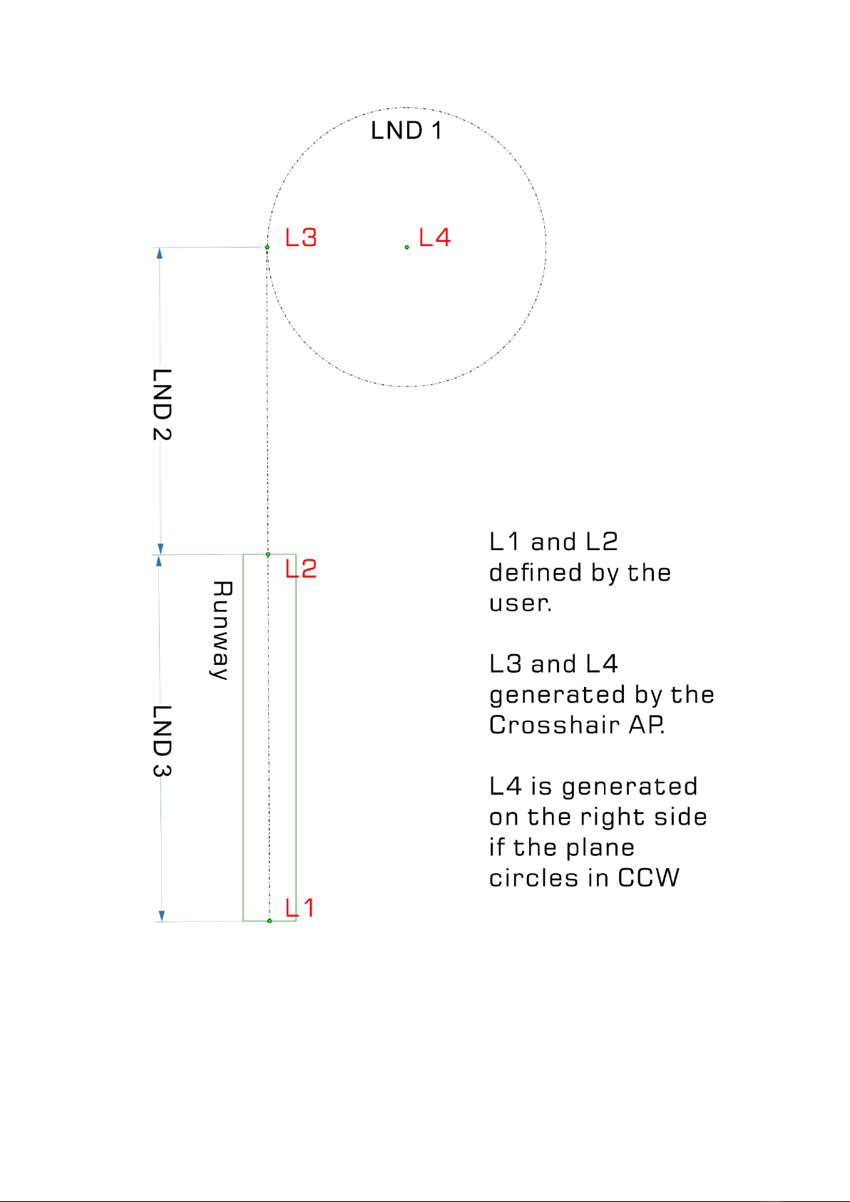
If there is an active runway set and available, the flight mode on the
upper left of the OSD screen will change to "LND 1"and the first stage of
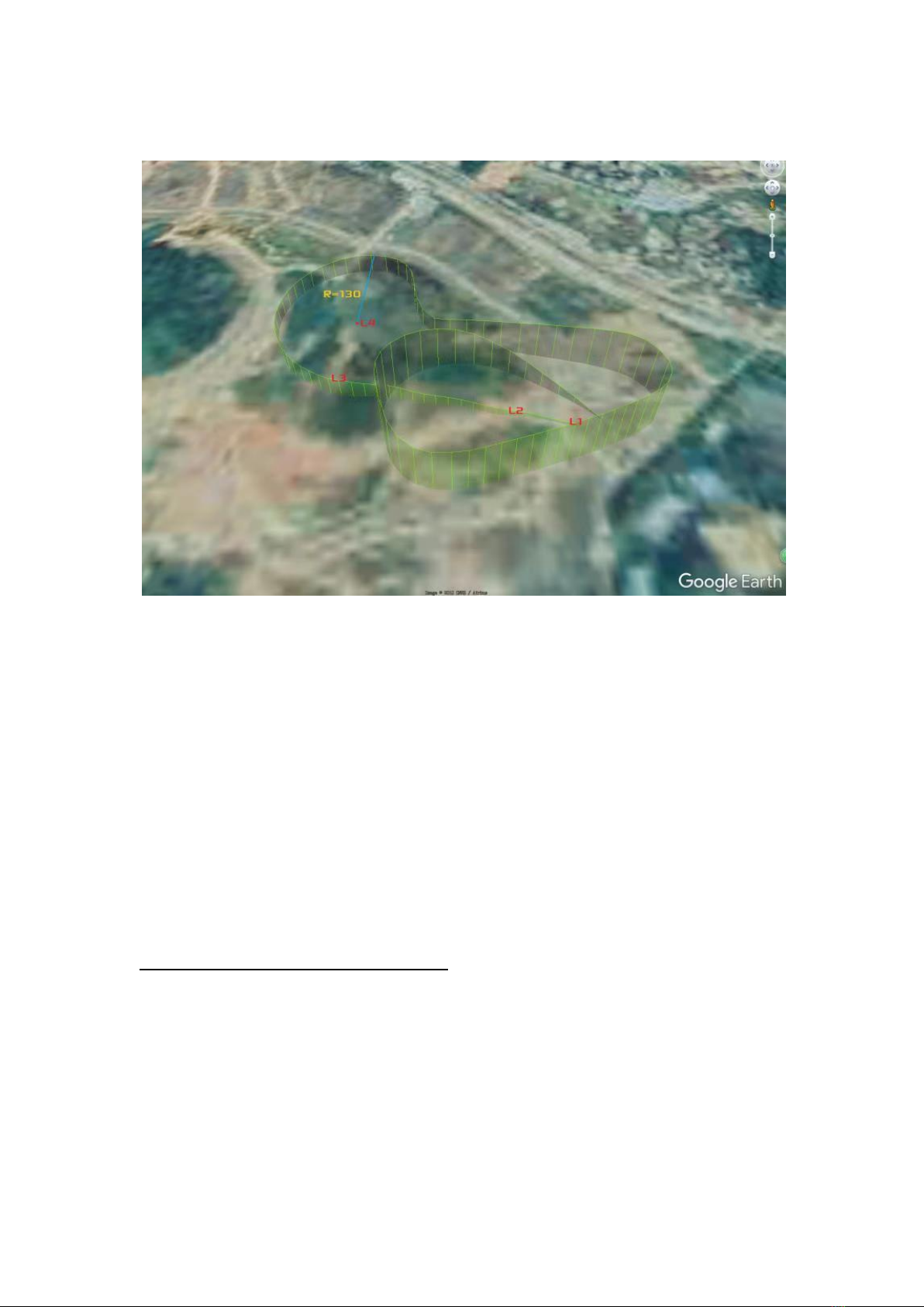
the landing procedure will be executed. The plane will fly towardL4 .
When the distance from theL4 is close to the standard circle
radius(defined by [AUTOPILOT SETTINGS->CIRCLE RADIUS]), the plane
will turn right, flying into the tangent of the circle and begin to circle
aroundL4 .The plane will climb/descend to L3 altitude at the highest
rate.
AsL3lays on the circle, the plane will fly closer to L3 with every circle.
Ideally the plane should align to the runway when it reaches L3.
If the altitude and distance are close enough to L3(<10m), the plane will
enter the second stage of landing, LND 2.
Here, the plane gradually descends along the L3-L2line, and flies
towardL2at the speed defined by [AUTO LANDING->LANDING
SPEED] . Once it reachesL2, the plane enters LND 3 stage.
It begins to monitor the altitude using the sonar, and flies toL1 to touch
down. Once the sonar altitude is less than the throttle cut altitude (can
be defined by [AUTO LANDING-> THR CUT ALT]), the AP enters LND
4 stage to turn off the motors and prepare for touchdown.
LND 5 stage is only used if the brake function of the AP is set active by
[AUTO LANDING- BRAK ALT]. The plane will enter LND 5 stage to brake

or reverse the thrust if the sonar altitude is less than the [BRAK
ALT].During the brake period, the E9 port of AP outputs a 1800us PWM
signal. After the plane stops or braking time (4 seconds)is up it restores
to 1000us.
The menu item[AUTO LANDING-> Landing Angle] is used to define the
attack angle for touchdown in LND 3/4 stage. In LND 3/4 stage when the
airspeed of the aircraft is greater than[AUTO LANDING-> LANDING
SPEED], the AP flies with a 0 degree attack angle. As the speed of the
plane decreases, the attack angle will automatically increase
progressively. At a speed of 35km/h the attack angle reaches the value
defined by the user.
WARNING: In LND 1/2/3 stages of the landing, once the THR stick on the
transmitter is moved to a position greater than 50%, the plane
temporarily enters STB mode. The mode switches of the transmitter are
still in positions of RTH combination. The mode switch doesn't match the
flying mode until you re-switch it.
The RUNWAY-SCAN Function:
The aforementioned automatic landing process is highly dependent on
the barometer. Circling around L4, approaching L3, and descending to L2
and ready to turn-off the engine. These actions rely on the barometer. If
the barometric altimeter reading is higher than the actual altitude, the

plane will mistakenly think that there is still enough altitude below, and
continue to land and hit the ground unexpectedly.
The barometric altimeter relies on the recorded air-pressure of the
takeoff point. After a long flight ( > 30 minutes, or even several hours),
the air pressure at takeoff will likely change. At this time, the barometric
altimeter will not be able to accurately estimate its altitude relative to
the takeoff point. It can be worse if we fly from point A to point B and
land automatically. The barometric altimeter readings will hardly make
any sense at the remote runway.
In order to solve the above problems and reliably perform automatic
landing, we need to use a non-barometric tool. Theoretically, sonar can
also be used for runway scanning but practically it should be avoided.
We take runway-1 as an example to explain how it works.
First, activate the runway scan in the menu and change the setting of
[AUTO LANDING-> RUNWAY 1-> SCAN RUNWAY]from "Disable" to "2
Times".
Second, set[AUTO LANDING-> SCAN RUNWAYALT = 25](25 is taken as an
example only). These settings will allow the plane to start scanning from
the altitude of 25 meters and fly over the runway no more than 2 times.
The APwill use the laser altimeter to measure the altitude above the

runway, and will calibrate the barometer for automatic landing. In this
example, we define the maximum times of scans to be 2, but it can be
up to 9 if you need.
The following is a detailed description of runway scanning:
1. The plane has entered the automatic landing mode LND (it can be
triggered by either moving the ELE stick to 4 corners in RTH mode, or by
presetting plane's behavior after the last waypoint is executed in WPT
mode).
2. The altitude of the plane is adjusted to the proper circle altitude and
circled around L4. The "proper circling altitude" is calculated from:
AltitudeTrim
=
The current ASL(from GPS) - L1 ASL - The current barometric
altitude
*ASL stands for Above Sea Level
CircleAltitude
= L4 Altitude -
AltitudeTrim
In this example, when the ground pressure changes little, the calculation
result of the
AltitudeTrim
is almost zero. When landing in a different
place, the error of altitude may be 100 meters or even more. We used
GPS altitude to calibrate the barometer, however doing so we also

brought in the GPS error. Nevertheless, as the GPS altitude error is
usually less than 10 meters, it is safe to apply it on a 30m or a higher
altitude of L4 / L3.
3. The plane maintains an (initial) SCAN RUNWAY ALT (25 meters in this
example) and flies over the runway. This SCAN RUNWAY ALT parameter
is added to the ASL of point L1. For example when you record L1 (or
upload from the GroundStation), the ASL of L1 is 90m.In this example
the plane will try to scan the runway at 90+25=115m ASL altitude.
The Flight controller will fly to 115 meters altitude according to the GPS
data. Due to possible GPS altitude error, scanning runway altitude
should not be set too low to prevent from crashing on the first attempt.
It is generally recommended to set an initial scanning runway altitude at
about 25 meters. In the worst case even if the GPS altitude error is 10
meters, it is still quite safe. If you expect the battery to retain enough
juice by the time of landing, you can define a higher SCAN RUNWAY ALT
and allow more scan times.
3. When the plane flies over L1, and if the laser altimeter gets a valid
reading, this altitude reading is immediately used to calibrate the
barometer, and GPS no longer plays a role in altitude estimation. The
plane engages a standard landing procedure. After having been
calibrated by the laser altimeter, barometric measurements are

considered valid for a short time, and accurate enough to perform the
automatic landing safely.
4. If the plane flies too high above the point L1 and cannot get a laser
altitude reading (usually it should be less than 25 meters to obtain an
valid laser altitude, the scanning distance will increase in a dark
environment), the plane will circle around L4 again, and then perform
the next runway scanning at a 5 meters lower then previous altitude. If
the very first scan is a success, no more scans will be performed, and the
plane will proceed with the normal landing procedure.
5 meters altitude reduction between 2 consecutive scans is a constant
value, and cannot be edited by user. If your runway scan altitude is set

high (for example, 40 meters), we usually recommend to increase the
maximum number of scans simultaneously (for example, to 6 –to ensure
that the plane can detect the runway before all scan takes are used up).
If the plane fails to detect the runway after the set number of scans, it
will use the GPS-calibrated altitude value to perform the landing
procedure.
The above illustration shows the runway scanning process set to a
maximum of 4 times. The plane scans the runway from SCAN RUNWAY
ALT, and descend 5 meters for the next pass. With any successful scan
the plane proceeds to landing.
The Youtube link below is a video of a 200 KM long range flight ending
with auto landing. At about 5'22, the plane enters the scan runway
procedure. The first attempt of scan was already successful, so the plane
landed automatically wasting no more time. You can see the entire
landing procedure:
https://www.youtube.com/watch?v=G8jQCiyTZHQ&t=250s

In the screenshot, LND1SCN1@23m indicates that the plane is trying the
first scan, Stage 1 (circling around L4), and the attempted altitude is 23
meters (relative to the runway)
It can be seen in this screenshot that after 200 KM of flight, we need to
use the scan result of the laser altimeter to correct the barometric

altimeter, and the
AltitudeTrim
=-39.9 meters. The objective
barometric altitude of the plane in the screenshot is -6 meters. In fact,
after landing we can see the ground barometric altitude reading was -38
meters, so this circling altitude is actually about 32 meters from the
ground, which is safe. From the animation on the upper-left corner of
this video you can figure out how it works.
Appendix A:
What is "Cross-track error" and how to tune the plane to get
minimum Cross-track error:
The above diagram describes the concept of "Cross-track error". Usually
in WayPoint (WPT) mode your plane would head for the target and fly to

it, which is good enough. But during Landing we also need to control the
distance between the plane and the line that we should follow. This
distance between the plane and the route line we call the "Cross-track
error".
Before tuning Cross-track-relative settings please make sure your plane
flies quite straight in STB mode and accurately flies toward the target in
WPT mode.
To get assistance in tuning the Cross-track error, please enter the
[OSD SETTINGS-> BR Area (Bottom-Right Area)] menu and select
[CROSSTRACK]. In waypoint mode the chart displayed in the lower right
corner indicates the current Cross-track error and altitud eerror.
Cross-track error and altitude error will be displayed as curves
indifferent colors (GREEN and WHITE). In the OSD below, the white
number in the red circle indicates the yaw distance (in centimeters,
positive value indicates that the aircraft is on the left side of the route)

Set 2 or more waypoints with 1km spacing and fly the plane in WPT
mode. Observe the behavior of the plane.
Green=Perfect, Red=P is too High, Brown=P is too Low
We use P/I/D parameters to control the cross-track performance.
Use [AUTOPILOT SETTINGS->CROSS-TRACK-P/I/D]to tune up the plane
till you get the best Cross-track performance. Ideally the plane should fly
dead on the route or very slightly oscillate to left and right in long-term
period. (Cross-track error reading varies between -100~100 or a
narrower range)

You can also adjust the parameters when the plane is in the air by a pair
of data-radios and mission planner software.
About PID tuning:
P(Proportion) is the most important parameter out of the three.
A too high P value will cause short-term period oscillation. The plane will
frisk from left to right frequently. A too low P value will cause flying
alongside rather than by the route, or long term period large amplitude
oscillation.
First please set I=0 and D=0. Try different P values until the plane flies
almost on the route or only with a little oscillating.
Use a little bit D value to reduce the oscillating.
If the plane flies alongside the route but still not by the route with a very
small Cross-track error, try to use I value to get it back onto the route.
For example, a reasonable settings combination of mini Crosswind plane
is:P=9, I=5, D=10 (these parameters are in the pre-set models).
Appendix B:
How to upload/download a runway by Mission Planner:
We explained in the above portion of the manual how to set L1/L2 to
define a runway(by placing the plane at L1/L2 and recording the
longitude/latitude/Altitude via the menu).Doing it this way demands
your physical presence on location.

However, you can also use Mission Planner to define a runway even if
you have never been there. Mission Planner software can be used to get
this job done (we hope to modify MFD GCS to do that soon, too).Please
note that we are using mission planner in a particular way to upload /
download the runways here, you have to pay attention to read the
following information.
The next screenshot shows how we defined a runway 200km away on
the launch site. To upload a runway you have to click on the map to
define 2 points. The first point you click in mission planner (on the "Flight
Plan" page) will be considered as L1 of the runway (the point for
touchdown). The second point you click will be considered as L2. To
upload a runway to AP you have to obey the following protocol:
Other MyFlyDream Autopilot System manuals