MyFlyDream MFD User manual

www.MyFlyDream.com
1.Features and hardware
MFD has build-in 3-axis gyro, 3-axis Acceleration sensor ,3 axis digital compass and
barometer. AP has two CPUs, one for the MFD attitude calculation, the other in charge for
the OSD and fly logic control. Base on this advance hardware, AP can be used for plane
stabilized, way point with altitude fly, and achieve autopilot and auto fly.
MFD AP’s advantage feature included:
1) Full attitude AHRS, max roll angular is 2000deg/s
2) Pixel-level black and white OSD, re-flash rate >30fps, no lag OSD flash
3) Intergraded MFD Auto Antenna Tracker (AAT) support, can use with MFD ATT directly
4) Through the OSD manual can setup and edit all parameters, and waypoint
5) Support MAVLink protocol, and can connect with third party open source ground station,
such as APM planner,

2.Specification
Power supply
7~20V (recommanded12V)。
can using for 5V supply with special connection
Current
<200ma@12V(included GPS,without other electronics)
PWM input channels
6
PWM input channels
4(RX in PPM mod,can have 4 more PWM output)
Maximum rolling angular
2000 degree/S
Flight mods
Manual, stabilized, Circle, Waypoint, Return to launch
3.OSD
4.Connection
MFD AP’s connections from A~J connection as the picture show above
编号
名称

A) Power
12Vpower supply
B) CH1~CH6 Input
CH1~CH6 PWM inputs,connect to receiver
C) CH1~CH4 Output
CH1~CH4 PWM outputs to the servos
D) GPS
To GPS
E) Data
Digital telemetry (option)
F) Camera
To camera
G) AV-TX
To video transmitter
H) AUX
Auxiliary port for sonar ..ETC (option)
I) Sensors
To current sensor board (for current sensing and battery
voltage sensing )
J) EXT
Extended port for air speed sensor (option)
Connect to the device as the picture show below: put the MFD AP
connection pins facing to you
A) Power

This port will supply the power to the MFD AP. The AP has it own
voltage regulator, can be power from 7-20V, but the camera and the
video transmitter will also share the power directly from this port.
Most of the camera and video TX are 12V, so we recommend you to
power the MFD AP with 3S lipo, and will make the connection more
pretty and easy.
If you want to power up the MFD AP with 5V, leave the A1 (12
positive empty, no connection) and connect the ground (negative) to
the A2 pin. And the 5V positive connect to the servo output or the
receiver 5V input. Will show up in the picture below.
12V power supply connection:
pins
Use for
A1
12V positive
A2
Ground or negative
5v Power Supply connection:
pins
Use for
A1
NC (No connection)
A2
Ground or negative
E3(From data port)
5V positive
The servo output and the receiver power are not connected with

MFD AP. They are separated power from the MFD AP; you have to
supply power to the servo and the receiver.
B) CH1~CH6 Input
Connect to the RC receiver, as the picture show the top is signal and
the middle is power supply to the servo and the receiver, they are
internal connected. The bottoms are grounds they are internal
connected also. Power to this port will not power up MFD AP, if the
main power port is not connect to the power.
CH1~CH6:
channel
connection
CH1
AIL
CH2
ELE
CH3
THR
CH4
RUD
CH5
Mode switch A (2 postions)
CH6
Mode switch B(3postions )
MFD AP will need one two positions and one three positions switch to
switch the flight modes, The three position switch connect to the AP
CH6.
Use PPM receiver

MFD AP support PPM sum signal input, if you r receiver can output
PPM, then the connection is piece of cake, and using one servo wire will
provide all the signals to the MFD AP.
A) For Futaba serial receiver, PPM channel orders for channel 1-4 are AIL,
ELE, THR, and RUD. Use the jumper comes with the MFD AP,
connected to CH6, and then PPM signal to CH5.
B) For JR serial receiver, PPM channel orders for channel 1-4 are AIL, ELE,
THR, and RUD. Use the jumper comes with the MFD AP, connected to
CH5, and then PPM signal to CH6.
3 MFD AP will auto select the PPM order base on the jumper position。
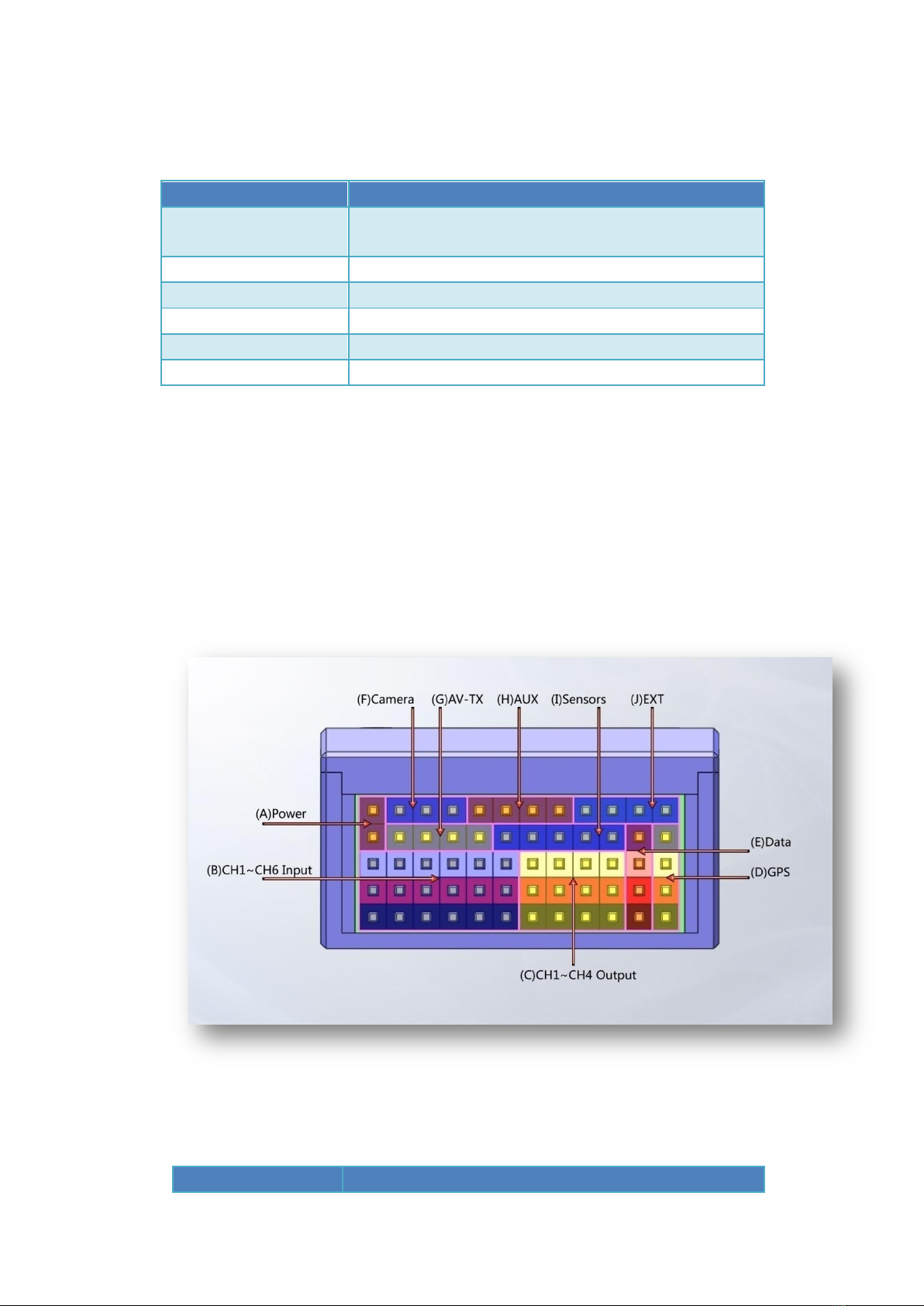
C) CH1~CH4 Output
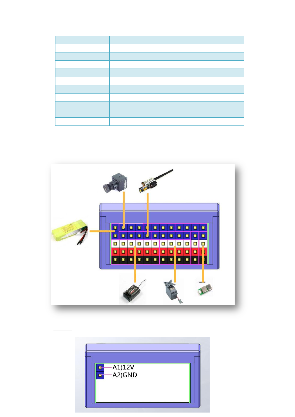
D) This port used for servo connections, use for control your airplane.
White color pin is signal pin, red is power positive, and black is the
ground. The red pins are internal connected to the receiver input
CH1-CH6.
CH1~CH4 output functions
通道
用途
CH1
AIL servo output

CH2
ELE servo output
CH3
THR ESC output
CH4
RUD servo output
E) GPS
Connect the GPS to this port.
插针
用途
D1
TX (default is no connection, the LS20033GPS come with the AP don
need it)
D2
RX(To the GPS TX) Default GPS baud rate is 38400
D3
3.3V power to the GPS
D4
Ground
F) Data
This port use for the telemetry data radio
插针
用途
E1
TX (to the telemetry radio RX)
E2
RX (to the telemetry radio TX)
E3
5V power (can be short the jumper inside the AP to change to 3.3V)
E4
Ground

G) Camera
Camera connecter (If you power AP with 12V, and camera is 12 V can
connect to it directly, make sure your camera are in the same power
range of the input power of the AP, they are internal connected)
Pin
USE
F1
GND Ground
F2
PWR Power (voltage is same as the AP Power input A1 pin)
F3
VID (Camera video signal)
If your camera voltage is difference, you have to power the camera
separately.
H) AV-TX
Connect your video transmitter here
插针
用途
G1
GND Ground
G2
PWR power (voltage is the same as A1 pin of the AP)

G3
VID video output with the OSD information to the video TX.
G4
AUD Audio output for the ATT tracker. Connect to the Video TX
audio channel
If you video transmitter is difference from the AP power, you have to
power the video TX separately.
I) AUX
This port is use for connect AUX (optional) can connect to ultrasonic
sensor and other AUX. default is not connected.
插针
用途
H1
NC
H2
NC
H3
5V
H4
GND
J) Sensors
Those pins are for current sensor, battery voltage sensor and RSSI
input. Connect the sensor comes with the AP directly with the order

below.
插针
用途
I1
RSSI (0~5V)
I2
VOLT power pack (0~27V)
I3
CURR power current (0~100A)
I4
PWR 5V
I5
GND Ground
K) EXT
This is I2C extension port for using airspeed and other device.
插针
用途
J1
SCL
J2
SDA
J3
PWR 3.3 v
J4
GND
5.installation
for better performance, please mount the AP around the CG point of the
airplane. For small electrical airplane don’t need to use the dumping
material to mount the AP, use the double size tape or Velcro to mount
the AP directly to the surface. Always make sure the arrow on the AP is
facing forward of your airplane. And do your best to make sure the AP is

parallel to your airplane centerline,as the picture shows below.
:
because most of the setting can be done via the OSD menu, so if you
don’t have you video transmitter hook up, you can connect a monitor to

the G port of the AP to monitor the OSD display to set up the parameters
Turn on your controller and make sure the CH5 and CH6 is on the low
position. Around 1000us, if the connection is right, when power up you
can see the G and R led on the AP flash two times. (if regular receiver is
connected the flashing will faster, if PPM receiver is connected, will flash
slower),wait a second you will see the OSD on your monitor.
How to enter the OSD setting menu
Throttle on the low position, CH5 and CH6 on low position and turn
the right stick of your radio controller to the right low corner (Aileron to
the right and ELE goes down), wait at lease 2 second, the OSD will show
up ask you “enter menu?” when you see the display, turn the CH5 switch
to the high, Now you should see the setting menu.
How to exit the OSD menu
Throttle on the low position, CH5 turn to the low position
Navigating the menu
When you enter the menu, you can use the Elevator to go up and down
on the men,Turn the Aileron enter the selection or take the change.
When you done setting the selection, using the Aileron to the left back
to the preview meunu.。

First time power up
Please follow the below procedures to setup the AP:
1) radio CH5 and CH6 on the low position, on the OSD display you
should see the MAN(manual mode) on the left up corner of the
screen. Move the elevator rudder and the aileron you should see the
moving correspond to the stick. If you see the movement is reverse to
your input, please adjust the reverse servo setting on your radio。
When the AP is in MAN mode, AP the input signal will pass through
the AP and go to the servo. If your airplane is control right before you
install the AP, the servo reverse will not change when you hook up
the AP。
2) CH5 on low, CH6 on middle position is the STB(stabilized mode), the
OSD display will change the display on the left top corner from MAN
to STB. Manually bank your airplane left, point the airplane to the
front, the left aileron will go down and the right aileron will go up.
When you bank the airplane to the right, the left aileron will go up,
the right aileron will go down, to maintain the airplane back to level.
When you manually move the airplane nose up, the elevator will go
down, and when you move the airplane nose down, the elevator will
go up to maintain the airplane back to level. you can get a clear look
by looking at the picture below.

(airplane bank right ,aileron left is up, right is down)
(nose up, elevator down)

(when the airplane spin left, rudder to the right. When spin right,
rudder to the left.)
if the servo movement is not expected, enter the OSD menu, go to
PLANE SETTINGS, set the wrong movement channel to REV. for
instance, when nose up, elevator also goes up. You have to change
the ELE in the menu to the REV.
3) Common calibration, this is telling the AP how it installed in the
airplane. Put the airplane in still, make sure the right wing and left
wing are leveled, and the pitch are on the normal level fly position.
Go to the OSD menu setting, navigate to the COMMON CALIBRATION
Then select common calibration by using the aileron stick to the right.
Follow the display on the bottom of the OSD display, turn CH6 to the
middle position, then the AP will start common calibration. Wait until
the summery data show up and the time counting finished, you will

see the”QUIT” show on the OS, by using the aileron stick to the left to
finish the calibration.
In the COMMON CALIBRATIONthe parameters that are calibrated
show as below:
1. Aileron elevator and rudder center point of your radio
2. AP installation error, show as degree off the roll and pitch
3. AP internal gyro and ACC
When you exit the menu, you will see the horizon line will show up on
the level position。
6.OSD Layout

OSD display will slightly change base on the fly modes
A. Fly time
B. Fly modes。Has 6 modes including MAN/STB/WPT/CIR/RTH,
about 6 fly mode detail please refer to (8. Test fly)
C. heading。Heading to the north is 0 degree. East south and
west are 90,180,270.When the airplane’s speed are
greater than 20km/h. the heading data comes from the GPS.
When the speed is less than 20KM/H, the heading data comes
from internal compass and GPS combination.
D. GPS satellites。
E. RSSI,receiver signal strength.

F. Ground speed,unit: km/h。
G. altitude,unit: meter。Data comes from barometer.
H. Home direction indicator (when in waypoint navigation
mode, indicator will point to the current waypoint
direction. When in CIR circle mode, indicator point to
the circle point) when the indicator point to the 12 clock
direction, it means the home position or way point
position or circle point is in front of the airplane.
I. Airplane icon. Always on the center of the display.
Simulate the airplane when you looking at the back of the
airplane. Using this icon combine with the Artificial
horizon calculates by the AP, will give you a clear view
of the airplane attitude. If the mark is on top of
artificial horizon means the airplane is climbing,
otherwise is dissenting.
J. Artificial horizon, AP calculates the current attitude
and simulates a horizon line on the display.
K. Target direction. Only apply for CIR, WPT and RTL.
Indicate where is the target (home, waypoint, circle
point) base on the airplane heading, if this number is
0, it means the target is on the north direction of the
airplane.

L. altitude 。This number only shows when the AP is in
CIR,WPT,RTL modes. Indicate that the AP is trying to reach
the setting altitude. When this number change the number
type will become larger than regular to cause your tension
on this number. After 3 seconds, it will show as normal
number type.
M. Battery voltage, this data from the voltage sensor
building inside the current sensor module. The gauge
shows the percentage of the battery voltage left.to get
more accuracy showing on the gauge, you have to setup the
battery cells count inside the OSD menu. The AP will
assume that fully charged cells voltage is 4.2V.and the
3.7v is empty. If you don’t want to show the gauge, set
the battery counting to 0 S in the OSD menu.
N. Current。
O. Battery consuming. Unit: mah。
P. Home distance。In meter.
Q. Roll angle。Can be set to GPS coordinate display in the
OSD menu setting.
R. Pitch angle。Can be set to GPS coordinate display in the
OSD menu setting
S. Current throttle percentage. Fully length is 100%,
Table of contents
Other MyFlyDream Autopilot System manuals