Nac HotShot User manual

HOTSHOT
Version 1.0
User Manual
NAC Image Technology Inc
Pixoft Diagnostic Imaging Ltd
Feb 2005

2
Contents
Introduction....................................................................................................................3
Installation......................................................................................................................3
Software Installation ..................................................................................................3
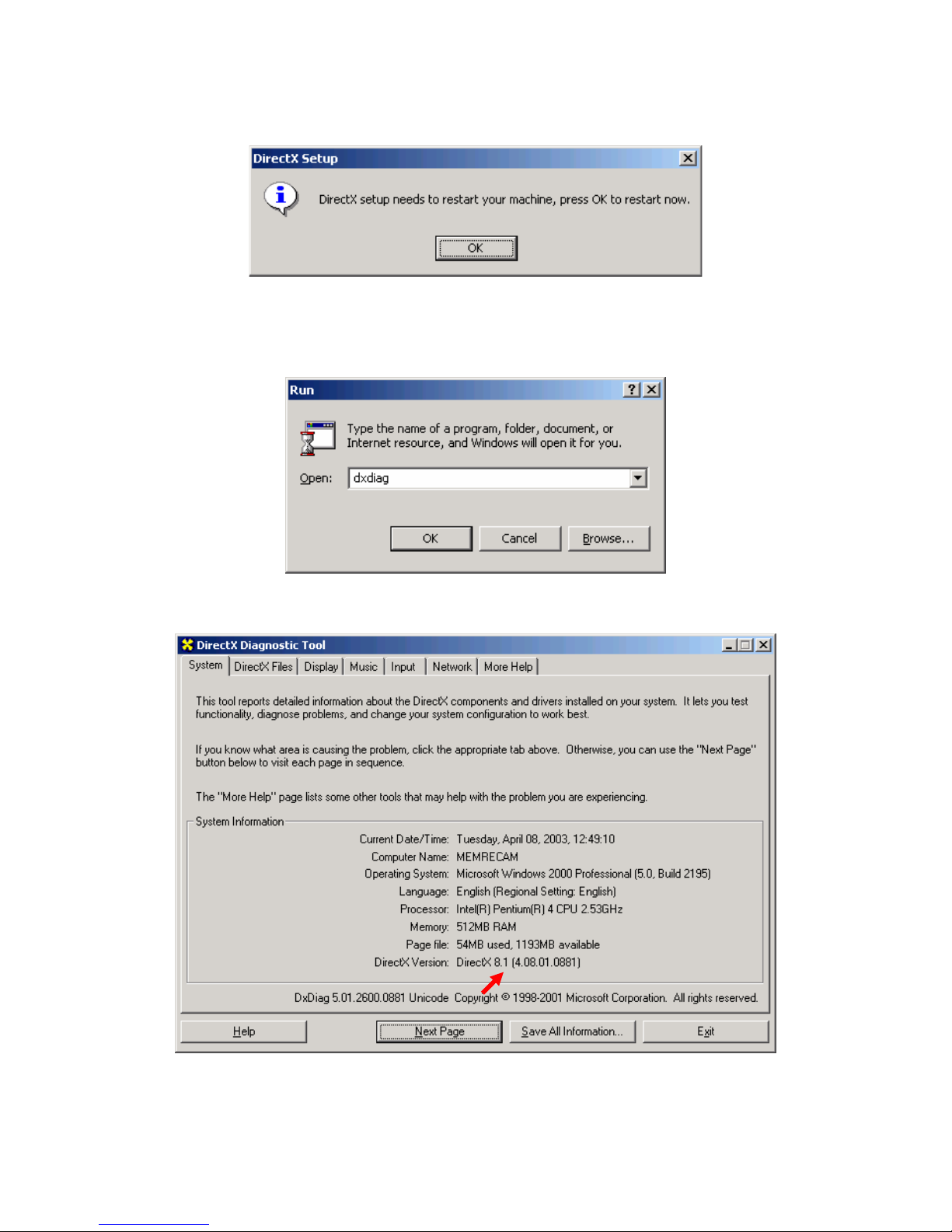
Microsoft™ DirectX..............................................................................................3
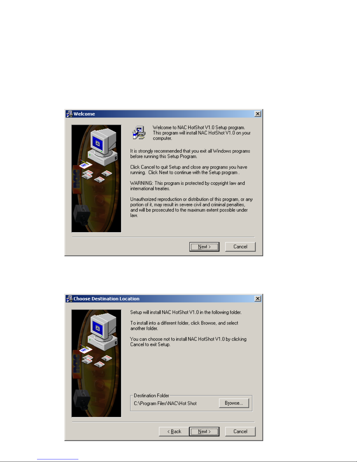
HotShot Link Software Installation .......................................................................7
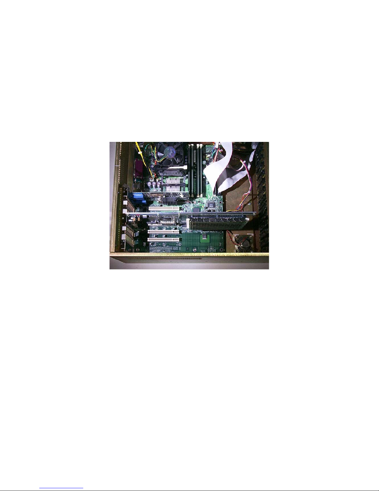
Hardware Installation...............................................................................................10
HotShot PCI controller configuration..................................................................13
Connections..............................................................................................................17
The software.................................................................................................................18
The Main Window ...................................................................................................18
Connecting a Camera...........................................................................................19
Recovering Data from the Buffer ........................................................................21
Making a Recording.............................................................................................21
Record Controls ...................................................................................................22
The Trigger ..........................................................................................................22
Play Controls........................................................................................................23
View / Measure / Reticle Functions.....................................................................24
Image Quality Settings.........................................................................................25
Recorded Information ..........................................................................................25
Record Information..............................................................................................26
Saving Out ...........................................................................................................27
Tools ........................................................................................................................30
Calibration............................................................................................................30
Reticle ..................................................................................................................30
Grid ......................................................................................................................31
Pixel Analysis ..........................................................................................................32
Pixel Peak.............................................................................................................32
Pixel Views ..........................................................................................................36
Miscellaneous ..............................................................................................................40
Preferences...............................................................................................................40
Start End Trigger Offset.......................................................................................41
Memory Segmentation.........................................................................................42
Advance Options..................................................................................................43
About........................................................................................................................44

3
Introduction
This manual describes the operational procedures for NAC HotShot high-speed
cameras.
Installation
Software Installation
For a trouble free installation you should first install the HotShot Link software and
then the HotShot PCI Board.
Microsoft™ DirectX
NOTE: Microsoft™ DirectX® version 8.1 is required. The following steps will guide
you through the inspection and update process of DirectX®.
1. From the Start Menu run the DirectX® diagnostic utility with the command
dxdiag. Click the [OK] button.
2. Inspect which version of DirectX® is installed in your computer. If the current
version is older than DirectX® 8.1 continue the update process. If DirectX® 8.1 or
newer is shown move onto the HotShot Link software installation. Click the
[Exit] button.

4
3. From the Start Menu run the DirectX® 8.1 installation file at X:\dx81NTeng.exe
where X represents the CD-ROM drive letter for your particular computer. Click the
[OK] button.
4. In the “Microsoft DirectX 8.1 Setup” window click the [Yes] button to begin
installation.
5. In the “Microsoft DirectX 8.1 Setup” window read the License Agreement. Click
the [Yes] button to accept the agreement.

5
6. Please wait while the DirectX® components and drivers are extracted and installed.

6
7. In the “DirectX Setup” window click the [OK] button to reboot.
8. Once Windows® restarts verify that DirectX® was updated by running the
diagnostic utility again. From the Start menu run the command dxdiag. Click the
[OK] button.
9. Verify that DirectX® 8.1 is now shown. Click the [Exit] button.

7
HotShot Link Software Installation
Follow these steps before installing the PCI boards:
1. From Windows Explorer or My Computer look inside the CD-Rom and find the
install program called HotShotInstall.exe.
2. In the “Welcome” window click the [Next] button.
3. In the “Choose Destination Location” window click the [Next] button to accept the
default target directory.

8
4. In the “Backup Replaced Files” window click the [Next] button to backup all
replaced files. If you do not wish to backup these files, click the No radio button and
then click the [Next] button.
5. In the “Select Program Manager Group” window click the [Next] button to accept
the default program folder.

9
6. In the “Start Installation” window click the [Next] button to begin the installation.
7. Please wait for the software components to be installed.
8. In the “Installation Complete” window click the [Finish] button to exit.

10
9. Finally shut down the computer from the Start menu.
Hardware Installation
CAUTION: Power down your system before opening the computer case. Handle
electronic devices with care.
1. Remove the computer case cover. Install the HotShot PCI Controller in any empty
PCI slot on your system board.

11
2. Connect the trigger ribbon cable to connector P4 on the HotShot PCI Controller.
3. Connect the power cable to the power supply.

12
4. Connect the HotShot PCI Controller to the Camera Head using the supplied Data
and Power cables.
Connect P1 on the PCI Controller to P1 on the Camera Head
Connect P2 on the PCI Controller to P2 on the Camera Head
Connect Power on the Power / Trigger Panel to Power on the Camera Head
Restore the computer case cover. Connect Power and turn computer system on.
External Signal Input/Output
These two connectors, on the camera head, are used to synchronise two or more
cameras together.

13
HotShot PCI controller configuration
NOTE: These steps assume that all software and hardware have been installed. Please
wait while the PCI card is recognized and the “Found New Hardware Wizard”
window appears.
1. In the “Found New Hardware Wizard” window click the [Next] button.
2. In the “Found New Hardware Wizard” window verify that the “Search for suitable
driver for my device” radio button is selected. Click the [Next] button.

14
3. In the “Found New Hardware Wizard” window check the “Specify a location” box.
Click the [Next] button.
4. In the “Found New Hardware Wizard” window click the [Browse] button.

15
5. In the “the “Found New Hardware Wizard” window click the [Browse] button.
Search for the driver located here:
C:\Program Files\NAC\HotShot\Drivers\Win2K\Epixxcw2.inf
Select the “Epixxcw2.inf” file and click to [Open] button.
You may however have specified somewhere different when you installed the
software. In the drivers folder there are also different folders for different operating
systems.
6. In the “Found New Hardware Wizard” window click the [OK] button.
7. In the “Found New Hardware Wizard” window click the [Next] button.

16
8. In the “Digital Signature Not Found” window click the [Yes] button.

17
9. In the “Found New Hardware Wizard” window click the [Finish] button.
10. Restart the computer from the Start menu.
Connections
If the installation above was followed correctly the computer is now setup to operate
in single camera mode. The trigger input on the power / trigger back plate needs to be
connected to a BNC trigger cable to provide an external triggering to stop/start
recordings.

18
The software
You can open the software from the following location:
START MENU|Programs|NAC HotShot|ShotShot
If you like you can copy this short cut to your desktop. See your Windows TM Guide
for how to do this.
The Main Window
When the software starts it will look like the screen shot below:
This window is divided into three areas. The first is the video window, which is the
black area in the top left. The area at the bottom is the play and record controls. The
area on the right is the Main controls and tools. The area on the right is split up into 3
tabbed pages, called Selection, Measure Tools and Pixel Analysis.

19
Connecting a Camera
On the selection tab there is a box at the top called ‘Camera / video list controls’, here
is a grid, and some control buttons.
To add a camera:
1. Click the Camera button on the top row in the middle.
2. Another window will appear called ‘Camera Inventory’; this will load up any
previously used cameras into the grid.
3. If the camera that is required for use is already in the list and the settings are
correct tick the box next to the camera’s name and click the ‘Connect Selected
Cameras’ button. This will then connect the camera and make it ready for use.
4. If however there is no camera in the list or another camera is needed, enter the
new camera information in the camera information boxes and click the ‘Add’
button. This will add the new camera to the list, and then tick the box next to
the camera’s name click the ‘Connect Selected Cameras’ button. This will
connect the camera and make it ready for use.
5. If the camera is already information is incorrect, select the camera in the list
and a blue bar will change position and highlight the newly selected camera.
Then click the ‘Edit’ Button this will then display the window below, here any
of the information can be changed and the changes saved by clicking the

20
‘Connect Selected Cameras’ button or disregarded by clicking the ‘Cancel’
button. Note the ‘Position’ field can not be changed.
6. After any changes have been made the camera can be connected by ticking the
camera’s name and clicking the ‘Connect Selected Cameras’ button, this will
also save all the cameras in the list even if not checked to memory for future
use. Clicking the ‘Cancel’ button will not connect any camera and disregard
any changed made.
The camera setup options are, Master and Slave, Master cameras will generate its own
timings and export them. Slave cameras will require timings from another camera.
The ‘Slave’ mode is used to frame synchronizes two or more camera. Colour Setup
applies a Bayer RGB pattern if it’s a colour camera or uses a single monochrome
channel if monochrome is chosen. Depending on the colour setup of the camera in
position 1 will determine which colour setup gets applied to all subsequent cameras.
7. The ‘Camera / video list controls’ box will now look like this. The status
column in the grid will show what tasks the camera is performing while the
software attempts to connect it. If more than one camera was checked in the
camera inventory window the software will attempt connection which each
camera in the position order starting with the camera connected to the PCI
board closest to the CPU on the motherboard, Position 1.
There are two other buttons above the grid:
1. The Folder icon on the button on the top left can open up AVI’s, streams of
BMPs, TIFs and JPEGs, and BIN’s (Raw Binary data from the PCI control
board’s buffers for review.
2. The ‘Default Settings’ button opens up the ‘Preferences’ window, see below.
Table of contents