Nady Systems WA-125U User manual

NADY SYSTEMS, INC.
6701 Shellmound Street • Emeryville, CA 94608
Tel: 510.652.2411 • Fax: 510.652.5075 • www.nady.com
SERVICE INFORMATION
(U.S.) If you are experiencing operation problem with your system, check out the support
page on the Nady website: www.nady.com for help and for contacting the Nady Service
Department. Should your wireless System require service, you must contact the Nady Service
Department at (510) 652-2411 for a Return Authorization (R/A) Number and a service quote
(if out of warranty). Make sure the R/A Number is clearly marked on the outside of the pack-
age. Cashier’s check or money is enclosed (If not prepaid with credit card), and ship the unit
prepaid to: Nady System Inc., Service Department, 6701 Shellmound Street, Emeryville, CA
94608. Include a brief description of the problem you are experiencing, for service of a unit
under warranty follow the instruction of your Warranty Card regarding Warranty Service.
(International) For service, please contact the NADY distributors in your country through the
dealer from whom you purchase this product.
DO NOT ATTEMPT TO SERVICE THIS UNIT YOURSELF, AS THAT WILL VOID YOUR
WARRANTY.
OWNER’S MANUAL
WA-125U
Single Channel UHF Wireless
Portable PA System

15
SPECIFICATIONS
AMPLIFIER SPECIFICATIONS
Audio Output Power ......................................................................................................... 20W (MAX)
Speaker Load ........................................................................................4 Ohms (6-1/2 inch Speaker)
Supply Voltage .................................................................. External AC adaptor or DC (12-15V)/1.2A
Internal Power 8xD alkaline or 12V/1.2A rechargeable battery
Power Consumption .................................................................................................................40VAC
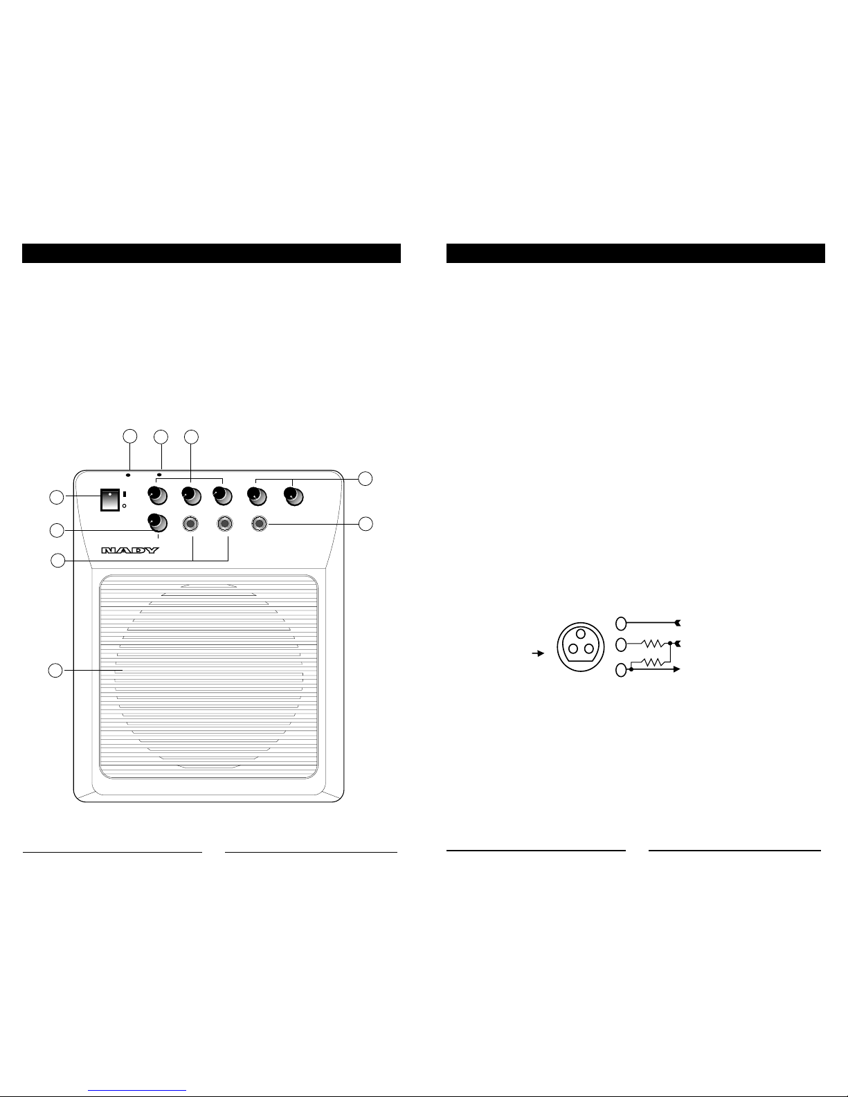
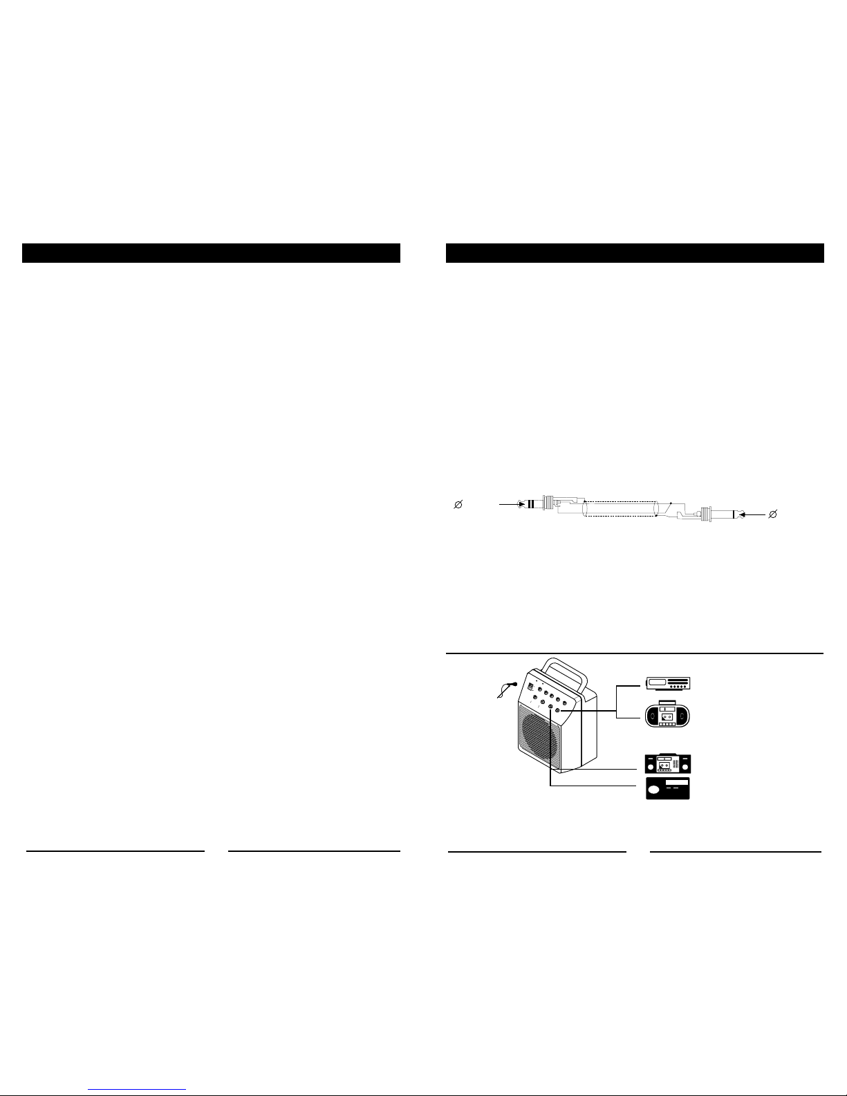
Connectors .............................................. AC/DC in, 1/4” (6.3 mm) unbalanced MIC/AUX/REC jacks
Input Sensitivity MIC, AUX .......................................................................................... 18mV, 132mV
REC output level ......................................................................................................................360mV
Frequency Response .......................................................................................50Hz to 20kHz +/-3dB
Total Harmonic Distortion ....................................................................................... <1% THD, normal
Signal-to-Noise Ratio (at rated output) ...................................................................................... -75dB
Tone Control Range ...............................................................+/-5dB (BASS 100Hz/TREBLE 10kHz)
Volume/Level Controls ...............................................................MICS, AUX, ECHO, BASS/TREBLE
9V battery Charger Current .............................................................................................. 5-70mA DC
Dimension ............................................................................ 8.3” x 10.6” x 5.4” (211 x 270 x 137mm)
Weight ........................................................................................................................... 5.3lbs (2.4kg)
WIRELESS RECEIVER SPECIFICATIONS
Frequency Response ...........................................................................................100Hz-16kHz, -3dB
Harmonic Distortion ............................................................................................. <0.6% THD, normal
Signal-to-Noise Ratio (REC out) ............................................................................................... -80dB
RF Carrier Frequency........................................... ........ Single UHF Frequency (797-805MHz range)
Frequency stability ..............................................................................+/- 0.005% Crystal Controlled
Modulation ............................................................................................... FM (F3E), +/-20kHz normal
Unwanted Signal Rejection ....................................................................... 60dB image and spurious
Squelch Controls ..................................................... External adjustable (-65dBm/Min, -95dBm/Max)
LED Indicators ..................................................................................................RF ON (GREEN LED)
Antennas ............................................................................................4.0” (10.2 cm) Internal antenna
Operating Range ................................................. Up to 200 ft. typical (depending on site conditions)
Up to 300+ feet (optimum line-of-sight)
TRANSMITTER SPECIFICATIONS
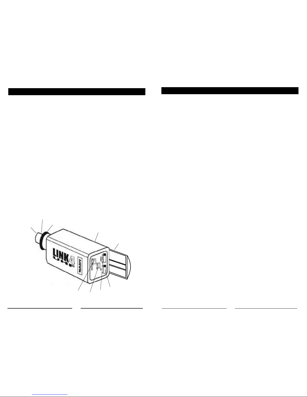
Models Available ..................... UH-4 Handheld, UB-4 Bodypack, and LINK 4 SNAP-ON transmitters
RF Output Power ................. +14dBm (25mW normal), +17dBm (50mW maximum allowed by FCC)
Harmonic/spurious .......................................................................................................-50dBc normal
Antenna Type .....................................................UH-4: Integral. UB-4: External permanent attached
LINK 4: Integral into hardwire Mic
Controls ................................................. Transmitter ON/Mute/OFF switch, Audio Input level control,
Phantom Power On/Off (LINK 4)
Audio Input Levels ....UH-4: 24mV. LINK 4: 24mV, UB-4: 225mV (Instr.), 310mV (HM), 75mV (Lav.)
Impedance ...................................UH-4: 3.3kΩ. LINK 4: 360Ω, UB-4: 500kΩ (Instr.), 2kΩ (HM/Lav.)
Connector .................................... UB-4: 3.5mm locking jack, LINK 4: XLR with 9V Phantom power
Indicator ................................................................................................Power and Low Battery LEDs
Battery Type ................................................................................ 9V alkaline or rechargeable battery
Battery Life ............................................................................................................ 8-10 Hours normal
Dimensions .............................................................. UH-4: 9.5” x 2.0” [L / Dia.] (24.13 cm x 5.08 cm)
UB-4: 2.5” x 4.25” x 1.0 [W / D / H] (6.35 cm x 10.80 cm x 2.45 cm)
LINK-4: 1.5” x 4.5” x 1.5” [W / D / H] (3.81 cm x 11.43 cm x 3.81 cm)
Weight (w/o batteries) .....................UH-4: 6.6 oz (187 g), UB-4: 3.1 oz (88 g), LINK 4: 2.6 oz (80 g)
TABLE OF CONTENTS
INTRODUCTION ........................................................................................................... 2
USING THIS MANUAL .................................................................................................. 2
SYSTEM FEATURES .................................................................................................... 3
WA-125U CONTROL AND CONNECTIONS ................................................................. 4
WA-125U OPERATING INSTRUCTIONS ..................................................................... 6
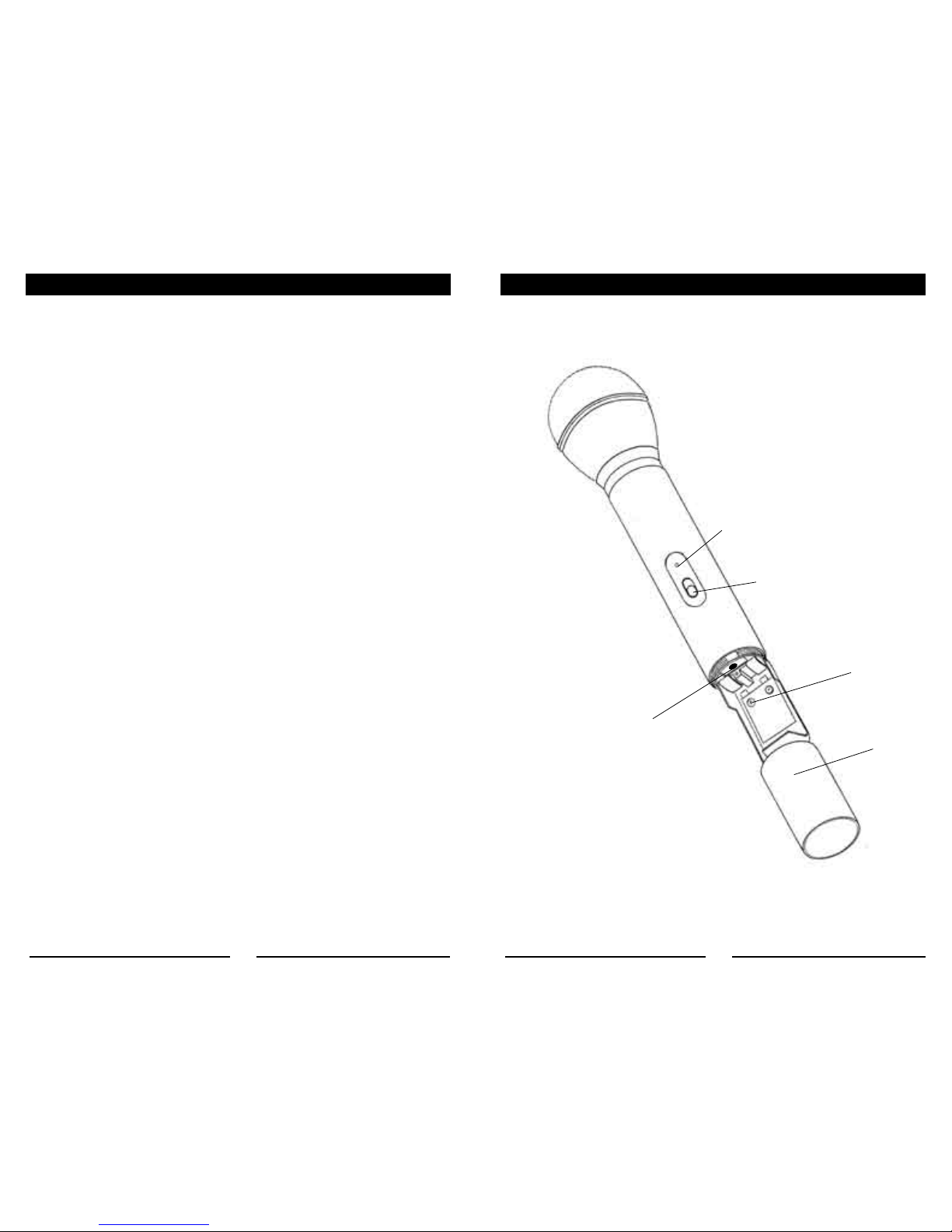
UH-4 HANDHELD MICROPHONE TRANSMITTER ..................................................... 8
UB-4 LAVALIER/HEADMIC BADYPACK TRANSMITTER .......................................... 10
LINK-4 PLUG-IN TRANSMITTER ............................................................................... 13
SPECIFICATIONS ....................................................................................................... 15
SERVICE INFORMATION ....................................................................... BACK COVER
2
INTRODUCTION
Thank you for purchasing a Nady WA-125U Wireless UHF Portable P.A. — and congratulations on
your choice. The WA-125U is the most compact of the popular line of Nady wireless P.A.’s. Ideal for
many applications, including use in classrooms, conference/meeting rooms, churches, health clubs
and small auditoriums, it is powerful, yet lightweight and easily portable. We are sure you will find
this versatile system a powerful and useful tool for your presentations.
USING THIS MANUAL
This booklet gives instructions for the operation of the WA-125U wireless portable P.A., including
handheld, lavalier, and Headmic™ systems. Please read the instructions for your system com-
pletely before operating this unit. This manual will first list the features of the WA-125U and then
will take you step by step to show you how to operate your new system. After reading the receiver
instructions, turn to the section of the booklet that covers the type of transmitter used with your new
system. Each section will give you detailed operating instructions. Also included in this manual are
system specifications and servicing information.
Specifications and design subject to change for improvement purposes without prior notice.

14 3
SYSTEM FEATURES
WA-125U Receiver/Amplifier
• Powerful 20W audio output
• Operation in the wide-open, uncluttered upper UHF band (available on single frequencies in
range 797-805MHz) for optimum operating range and freedom from interference
• Built-in echo/reverb
• 1/4” unbalanced input jacks: 1 MIC, 1 AUX; one 1/4” unbalanced RECORD OUT; treble and bass
controls
• Wireless system features noise reduction companding circuitry for quietest operation with a wide
dynamic range.
• Available with choice of UH-4 or Link-4 handheld mic, UB-4 lavalier/headset mic transmitters
• External AC, DC (12-15V) or internal battery powered (8 X “D” alkaline or rechargeable batteries)
• Optional RB-120 (12-15V) internal rechargeable battery available
• Mountable with optional MST-4B aluminum tripod stand
• Internal charging ports for transmitter 9V (Ni-Cad or Ni-MH) rechargeable batteries
• Small and lightweight—only 8.3” x 10.6” x 5.4” (211 x 270 x 137mm) and 5.3 lbs. (2.4 Kg)
UH-4 Handheld Microphone Transmitter
• Nady DM-10D neodymium cartridge delivers transparent vocals, maximum feedback rejection and
minimal handling noise
• OFF/MUTE/ON switch for ease of use
• Unique screw-on battery compartment for quick pop-in battery replacement—uses standard 9V
alkaline battery
• Single LED indicator flashes once for unit on; lights steady for low battery alert
• Input level control for optimum sound adjustment
• Rugged ABS housing with integral antenna
UB-4 Bodypack Transmitter
• Compact bodypack with screw on jack for instrument or lavalier microphone input
• OFF/MUTE/ON switch for ease of use
• Unique sliding battery compartment for quick pop-in battery replacement–uses standard 9V
alkaline battery
• Single LED indicator flashes once for unit on; lights steady for low battery alert
• Input level control for optimum sound adjustment (LT/HM)
• Rugged ABS housing with external antenna
LINK 4™ Plug-In Transmitter
• Compact microphone transmitter that converts any dynamic XLR hardwired microphone to wire-
less operation
• OFF/MUTE/ON switch for ease of use
• Unique sliding battery compartment for quick pop-in battery replacement–uses standard 9V alka-
line battery
• Single LED indicator flashes once for unit on; lights steady for low battery alert
• Audio LO/MED/HI gain selection for optimum sound
• Selectable 9V DC phantom powering for lavalier condenser microphone operation
• Standard locking 3-pin connector with adjustable threaded ring to provide secure connection to
any XLR handheld direct or to lavalier microphone cable
• Lightweight, ABS housing with integral antenna
Level Trim Adjust
For optimum performance, an INPUT SELECT SWITCH (44) is provided. You could select the
switch to LO/MED or HI gain setting defending to your microphone use. Depending on the average
distance between vocalist’s mouth and microphone, you can adjust the level for your application.
Factory setting is MED for hardwire dynamic microphone. This is a setting to be used in most typi-
cal close microphone applications. Set for maximum possible gain and headroom without notice-
able distortion of the high level peaks. Experiment and set for maximum possible gain without
audible distortion on the high level peaks.
Receiver Volume Controls Adjust
The PA sound output level is control by the volume control MIC/TS knob. If feedback (howling
sound) occurs, try first turning own the TREBLE CONTROL (7). If feedback still is present, try turn-
ing down the VOLUME (6) or repositioning the WA-125U with respect to the wired or wireless mic
being used.
The bodypack transmitter is now ready to use. The RF ON indicator on the receiver should now
be on, indicating a received signal from the transmitter. When ready to speak, slide the OFF/
STANDBY/ON SWITCH (42) to the ON position. Adjust the volume of the receiver as outlined in the
Receiver Operating Instructions section: Operating the WA-125U.
Notes:
• Selecting LOW gain setting can compromise the signal-to-noise and it is not recommended.
• The microphone ball on your hardwire microphone functions as an integral antenna. For proper
operation, it should not be cover or touch during operation.
• Observe care in selecting P.A. volume, transmitter location and speaker placement so that acous-
tic feedback (howling or screeching) will be avoided.
LINK 4™ PLUG-IN TRANSMITTER
37
38
39
40
41 43 42
44
45

ON RF ON
MIC/TX
ECHO
POWER
MIC
MIC
AUX
AUX
TREBLE
REC. OUT
BASS
WA-125U
UHF
WIRELESS AMPLIFIER
4
WA-125U CONTROLS & CONNECTIONS
1. Power ON/OFF switch
2. MIC and AUX signal input jacks
3. 6.5” round speaker
4. Power ON LED indicator
5. RF ON transmitter signal reception LED indicator
6. MIC/TX, MIC, AUX Volume controls
7. BASS-TREBLE Tone controls
8. RECORD output jack for recording or additional amplification
9. ECHO level control of echo/reverb in the channel signal
13
1
2
3
45 6
7
8
9
LINK 4™ PLUG-IN TRANSMITTER
Transmitters Set Up
The LINK-4 transmitter requires a single 9V battery to operate. To open the battery compartment,
slide BATTERY DOOR (37) downward to open the cover, exposing the BATTERY HOLDER (38).
Insert a fresh 9V battery according to the correct polarity as indicated on the transmitter body. Slide
back the door onto the original position. Make sure the cover is secured completely. Fresh Alkaline
batteries can last up to 10 hour of operation, but in order to ensure optimum performance, it is
recommended that the batteries should be replaced after 6-8 hours of use.
Handheld Microphone Installation
Step 1 Rotate the transmitter’s threaded LOCKING RING (39) counter-clockwise inward the
transmitter body until it stops.
Step 2 Hold your mic in one hand and the LINK 4 in other.
Step 3 Place your mic into the XLR CONNECTOR (40) and push your mic all the way down
untill a click sound.
Step 4 Lock the mic into place with the adjustable threaded LOCKING RING (39) by rotating the
ring clockwise, to the top of the transmitter
Step 5 To release the XLR CONNECTOR (40), turn the treaded LOCKING RING (39) counter-
clockwise and press the RELEASE BUTTON (45).
Lavalier Microphone Installation
You will need a male XLR to mini male XLR adaptor (Switch-Craft TA-4 or equivalent) to use a
lavalier microphone per the installation instructions. Then plug the lavalier microphone’s mini male
XLR into the adapter. The PHANTOM POWER SWITCH (41) should be turned ON for use with a
condenser lavalier mic which requires external phantom powering.
Note: The lavalier microphone you are using must terminate with a mini XLR or full XLR connector
and confirm to the pin assignments shown below. If they do not, the lavalier mic may not work with
the LINK 4. If you have any questions, please contact your Nady dealer or Nady Systems Service
Department.
The pin assignments on the LINK 4 XLR connector are as shown:
Microphone Operation
To turn it on, slide the OFF/STANDBY/ON SWITCH (42) to the STANDBY position first (transmit-
ter on, audio muted) or the ON position (transmitter and audio both on). You could also use your
hardwire microphone audio mute switch afterward. The BATT LOW INDICATOR LED (43) will give
a single flash in red, indicating usable battery strength. In case of dead or low battery, both LEDs
will either not go on at all or will stay on continuously, indicating that the battery should be replaced
with a fresh one. To preserve battery life, turn the transmitter off when not in use. To turn off, slide
the OFF/STANDBY/ON SWITCH (42) to OFF position. No LEDs will light up. The unit is now off.
XLR
Connector
Top View
3
1 2
Ground
Phantom Volt. (full 9V battery
voltage) switchable
Mic
Input
680
680
9V
9V
2
3
1

12 5
WA-125U CONTROLS & CONNECTIONS
10. Charging LED indicator for transmitter 9V rechargeable battery
11. Battery charger connector for one 9V transmitter battery
12. AC power adaptor input socket
13. AC adaptor input fuse
14. Mounting hole for use with optional MST-4B aluminum tripod stand
15. Battery compartment for 8 X “D” for batteries operation
16. External DC input jack
17. Electrical specifications label
18. RF mute threshold (squelch) adjust
19. Battery charging LED indicators for internal optional rechargeable RB-120 (12-15V)
DC charging mode
DC 12-15V
Recharge
Squelch
6F22
Recharge
6F22
AC
FUSE
AC IN :100-120V /60Hz
AC FUSE :1TA /250V
OUTPUT POWER (MAX):20W
CAUTION
RISK OF ELECTRIC SHOCK
DO NOT OPEN
¡
11
14
18
16
15
13
12
10
17 19
UB-4 BODYPACK MICROPHONE TRANSMITTER
33
30
32 29
31
36
Opening Battery Compartment
27
26
35
34
INPUT SELECTOR
SWITCHES
Instrument
HL
G G H L
Headworn
HL
G G H L
Lavalier
HL
G G H L
28

6
WA-125U OPERATING INSTRUCTIONS
11
Powering the WA-125U
AC POWER (12): Plug the AC adaptor to a wall outlet then insert the plug into the AC power adap-
tor input socket
(Note: Before connecting to AC power, make sure the working voltage of your WA-125U, either
115V AC or 230 V AC, as supplied and indicated on your unit (20) correctly matches your local AC
power.)
INTERNAL OR EXTERNAL DC POWER (16): The WA-125U may also be DC powered internally
with a 12V/1.2A rechargeable Gel-cell or using the optional external RB-120 (12-15V) DC power
supply plugged into the DC INPUT JACK (16)
(Note: To avoid damaging your unit’s power supply electronics, make sure that the DC input has the
correct polarity: positive center conductor and negative sleeve)
Attention: The DC INPUT JACK (16) will automatically switch between external DC or the
internal battery pack (8 X “D” cells). Inserting the external DC plug will automatically discon-
nect the internal DC power. This prevents damage to the internal batteries.
INTERNAL POWER (15): The WA-125U can also be powered by the internal (8 X “D” cells)
batteries.
(Note: Insert the batteries with correct polarity as marked. For longest operation, use only alkaline
batteries.) Replace the batteries when the output audio sounds muddy or distorted and has lower
volume or the range of the wireless shortens.
Operation
Before switching on the unit, make sure that the VOLUME CONTROLS (6) are off or at minimum
levels and that both of the TONE CONTROLS (7) are in the center and the ECHO (9) at minimum
position. This will prevent possible loud noises or damage to the speaker when the unit is turned on.
Switch the POWER ON/OFF (1) on the unit to ON. The POWER ON INDICATOR (4) will light red
to show that the system is on. The RF ON will light green to show the RF signal is received. After
the signal and/or the wireless mic are turned on, adjust the VOLUME (6), TONE (7) and ECHO (9)
levels as desired
The MIC INPUT (2) can be connected to a wired microphone or other such sound source. The au-
dio level in controlled by the MIC VOLUME (6). The AUX INPUT (2) can be connected to a cassette
or CD player or other such sound source. The audio level in controlled by
the AUX VOLUME (6). The REC OUT (8) can be connected to a recording
device input or to the input jack of a power amplifier to further amplify and
enlarge the audio power. The output is varied by the VOLUME CON-
TROLS (6).
The BASS and TREBLE CONTROLS (7) are used to decrease (turn left)
or increase (turn right) the frequency response for the final PA output.
They also help to reduce high or low frequency audio feedback during
operation.
The ECHO VOLUME (9) is used to adjust the sound effect to the PA system. The ECHO function is
only available when the MIC (wire mic) or MIC/TX (wireless mic) are used.
The RF MUTE (Squelch) TRIMPOT (18) can be used to eliminate RF interferences during wire-
less operation. This is most useful for making sure that when the PA is on the mic transmitter is
turned off there are no noises or radio interferences heard from the live PA, i.e. the audio is fully
muted. (Note: This control will not eliminate interference from other radio sources operating on the
DC+12V
MID
MIN
BUTTON TURNING DIRECTION
MAX
UB-4 BODYPACK MICROPHONE TRANSMITTER
Receiver Volume Controls Adjust
The PA sound output level is control by the volume control MIC/TX knob. If feedback (howling
sound) occurs, try first turning own the TREBLE CONTROL (7). If feedback still is present, try turn-
ing down the VOLUME (6) or repositioning the WA-125U with respect to the wired or wireless mic
being used.
The bodypack transmitter is now ready to use. The RF ON indicator on the receiver should now
be on, indicating a received signal from the transmitter. When ready to speak, slide the OFF/
STANDBY/ON SWITCH (33) to the ON position. Adjust the volume of the receiver as outlined in the
Receiver Operating Instructions section: Operating the WA-125U.
Notes:
• Turning down the gain too much can compromise the signal-to-noise and it is not recommended.
• The microphone has an external flexible wire antenna. For proper operation, it should not be
cover or touch during operation.
• Observe care in selecting P.A. volume, transmitter location and speaker placement so that acous-
tic feedback (howling or screeching) will be avoided.

same frequencies that can possibly affect the sound even while the mic transitter is on and being
used). In normal operation, the RF MUTE (Squelch) TRIMPOT (18) should be set clockwise fully
to the factory setting (Max. range). However, in areas of high RF activity, the RF MUTE (Squelch)
TRIMPOT (18) may need to be readjusted to compensate for the adverse conditions in a particular
location. Turning the RF MUTE (Squelch) TRIMPOT (18) too far counterclockwise will reduce the
range, but yield a quieter squelch audio mute function. Note that when the RF LED (5) extinguishes
during operation, the transmitter is out of range for that given location, and the user should move
closer to the receiver to re-establish the radio link.
Attention:
1. If feedback (howling sound) occurs, try first turning down the TREBLE CONTROL (6). If
feedback still is present, try turning down the VOLUME (5) or repositioning the WA-125U
with respect to the wired or wireless mic being used.
2. Keep line of sight between WA-125U receiver and wireless transmitter whenever possible
to ensure optimum performance and maximum range.
Stereo/Mono Wiring Illustration (for use with AUX input and
RECORD output)
For stereo to mono conversion of the signals to the AUX input and mono to stereo connections from
the RECORD output, wire the connecting cord as per the following illustration:
WA-125U Battery Charging Operation
The WA-125U has two ports in the rear compartment for charging a single 9V BATTERY (11) and
the optional RB-120 (12-15V) DC rechargeable battery. This battery charger can be used when-
ever the WA-125U is operated from AC power. If you are using rechargeable batteries in your
transmitter, you can replace them as necessary with freshly charged ones, even during use. The
discharged battery can immediately be put on charge. The charging LED INDICATORS (10) for
9V and (19) for 12V will light RED whenever a battery is taking a charge. When the battery is fully
charged, the indicator will turn GREEN.
Attention: This BATTERY CHARGER (11) can only be used for one 9V Ni-Cad or Ni-MH and
(16) for one 12V rechargeable at the same time. Never use them for any other type of battery
under any circumstance as this can result in damage to your unit and even danger from
exploding batteries.
POWER
RF ON
MIC/TXMIC
ECHOMIC
AUX
AUXRECOUT
TREBLEBASS
ON
WIRELESS AMPLIFIER
POWER
RF ON
MIC/TS MIC
ECHO MIC
AUX
AUX RECOUT
TREBLEBASS
ON
WIRELESS AMPLIFIER
POWER AMPLIFIER
PORTABLE RECORDER
PORTABLE CASSETTE
RECORDER
PORTABLE CD PLAYER
7
WA-125U OPERATING INSTRUCTIONS
10
To cassette recorder
3.5 mm
6.3 mm
To Rec out (8) or Aux (2)
Stand Mounting the WA-125U
The WA-125U can be mounted on the optional MST-4B aluminum tripod stand for convenient
placement in a higher position. Contact your dealer or the Nady service department. (See Page12)
Transmitters set up
The UB-4 transmitter requires a single 9V battery to operate. To open the battery compartment,
snap open the BATTERY DOOR COVER (26), exposing the BATTERY HOLDER (27). Insert a
fresh 9V battery according to the correct polarity as indicated on the transmitter body. Snap the
cover back onto the bodypack. Make sure the cover is secured completely. Fresh alkaline batteries
can last up to 10 hour of operation, but in order to ensure optimum performance, it is recommended
that the batteries should be replaced after 6-8 hours of use.
Input Connection and Input Selector Switches
The UB-4 is provided with a 3.5MM LOCKING JACK (29) for connecting the audio input selected.
Connect either the INSTRUMENT CORD (34), or the HEADWORN MIC (35), or LAVALIER MIC
(36) as desired, according to the input selected.
(Note: Use only the input audio source as per the input selected with the input audio Input Selector
Switch or the audio will not be optimal — a muddy or distorted sound may result.)
To secure the connection, turn the slip ring on the plug clockwise ti thread it on the jack. To unplug,
reverse the process. Slip the transmitter into a pocket or clip it onto you cloth or instrument strap (if
using the UB-4 as an instrument transmitter.)
The UB-4 is equipped with two INPUT SELECTOR SWITCHES (28) located under the
cover on the circuit board for selecting the type of audio input you will be supplying
to the transmitter. Select from the choice of three positions: INSTRUMENT (for guitar,
bass, etc.)/ HEADWORN MIC/ LAVALIER MIC. (G/H/L).
There are two switches, one with selectable position G, H, L and the other with G, HL.
To select inputs: (see chart on page 12)
A. Instrument — both switches to “G”
B. Headworn Mic — set one switch to “H” and the other to “H”
C. Lavalier Mic — set one switch to “L” and the other to “L”
Microphone Operation
To turn it on, slide the OFF/STANDBY/ON SWITCH (33) to the STANDBY position first (transmitter
on, audio muted) or the ON position (transmitter and audio both on). The POWER LED (30) will
stay on green and the LOW BAT indicator LED (bottom) will give a single flash in red, indicating
usable battery strength. In case of dead or low battery, both LEDs will either not go on at all or will
stay on continuously. During use, the LOW BAT will give a red flashing warning until it stays on
continuously, indicating that the battery should be replaced with a fresh one. To preserve battery
life, turn the transmitter off when not in use. To turn off, slide the OFF/STANDBY/ON SWITCH (33)
to OFF position. No LEDs will light up. The unit is now off.
Level Trim Adjust
For optimum performance, an INPUT LEVEL CONTROL (32) for LT/HM is provided. Adjust the
microphone gain by inserting a small slot-headed screwdriver to the adjustment knob, located on
the topside of the transmitter unit, next to the mic input jack. Factory setting is 1⁄2 full. This is a set-
ting to be used in most typical close microphone applications. Depending on the average distance
between vocalist’s mouth and microphone, you can adjust the level for your application. Set for
maximum possible gain and headroom without noticeable distortion of the high level peaks. It is
recommended that the level be set at about 1⁄2 maximum. Experiment and set for maximum pos-
sible gain without audible distortion on the high level peaks. on, indicating a received signal from
the transmitter. When ready to speak, slide the switch to the ON position. Adjust the volume of the
receiver as per in the receiver operating instruction section.
UB-4 BODYPACK MICROPHONE TRANSMITTER

98
UH-4 HANDHELD MICROPHONE TRANSMITTER UH-4 HANDHELD MICROPHONE TRANSMITTER
Transmitters set up
The UH-4 transmitter requires a single 9V battery to operate. To open the battery compartment,
unscrew the BATTERY COVER (22) with a counter-clockwise turn and remove the cover, exposing
the BATTERY HOLDER (23). Insert a fresh 9V battery according to the correct polarity as indicated
on the transmitter body. Screw cover back onto the microphone. Make sure the cover is screwed on
completely. Fresh alkaline batteries can last for up to 10 hours of operation, but in order to ensure
optimum performance, it is recommended that the batteries should be replaced after 6-8 hours of
use.
Microphone Operation
To turn transmitter on, slide the OFF/STANDBY/ON SWITCH (24) to the STANDBY position first
(transmitter on, audio muted) or the ON position (transmitter and audio both on). The LOW BAT
LED (25) will give a single flash, indicating usable battery strength. In case of dead or low battery,
the LED will either not go on at all or will stay on continuously. During use, if the LOW BAT stays on
continuously, it is indicating that the battery should be replaced with a fresh one. To preserve bat-
tery life, turn the transmitter off when not in use. Keep line of sight between WA-125U receiver and
wireless transmitter whenever possible to ensure optimum performance and maximum range.
Level Trim Adjust
For optimum performance, an INPUT LEVEL CONTROL (21) is provided for the transmitter. Adjust
the microphone gain by inserting a small slot-headed screwdriver through the adjustment hole,
located on the topside of the battery compartment, under the compartment cover. Factory setting
is 1⁄2 full. This is a setting to be used in most typical close microphone applications. Depending on
the average distance between vocalist’s mouth and microphone, you can adjust the level for your
application. Set for maximum possible gain and headroom without noticeable distortion of the high
level peaks. It is recommended that the level be set at about 1⁄2 maximum. Experiment and set for
maximum possible gain without audible distortion on the high level peaks.
Receiver Volume Controls Adjust
The PA sound output level is control by the volume control MIC/TX knob. If feedback (howling
sound) occurs, try first turning down the TREBLE CONTROL (7). If feedback still is present, try
turning down the VOLUME (6) or repositioning the WA-125U with respect to the wired or wireless
mic being used.
The handheld microphone is now ready to use. The RF ON indicator on the receiver should now
be on, indicating a received signal from the transmitter. When ready to speak, slide the OFF/
STANDBY/ON SWITCH (24) to the ON position. Adjust the volume of the receiver as outlined in the
Receiver Operating Instructions section: Operating the WA-125U.
Notes:
• Turning down the gain too much can compromise the signal-to-noise and it is not recommended
• The battery compartment on the UH-4 functions as a built-in antenna. For proper operation, it
should not be covered by the hand or touched during operation.
• Observe care in selecting P.A. volume, transmitter location and speaker placement so that acous-
tic feedback (howling or screeching) will be avoided.
24
25
23
22
21
Table of contents
Other Nady Systems Speakers manuals

Nady Systems
Nady Systems WA-120 User manual

Nady Systems
Nady Systems PSS-300 User manual

Nady Systems
Nady Systems MPA-400 User manual

Nady Systems
Nady Systems ProPower Plus Series PS110+ Instruction manual

Nady Systems
Nady Systems WA-120BT User manual

Nady Systems
Nady Systems MPA-30 Instruction manual

Nady Systems
Nady Systems ProPower Plus Series PS115+ Instruction manual

Nady Systems
Nady Systems P-Cab Speakers PCS-15X Instruction manual

Nady Systems
Nady Systems WA-120 User manual

Nady Systems
Nady Systems P-Cab Speakers PCS-8X User manual