Nailor UNI2-VAV User manual

Nailor reserves the right to change any information concerning product or specification without notice or obligation.
IOM-UNIVAVETINST
Date: 8-2021 Supersedes: NEW
nailor.com
UNI2-VAV Electronic Thermostat

Installation and Operation Manual ●UNI2-VAV Electronic Thermostat
Nailor reserves the right to change any information concerning product or specification without notice or obligation.Nailor reserves the right to change any information concerning product or specification without notice or obligation.
IOM-UNIVAVETINST
Date: 8-2021 Supersedes: NEW 2 of 12
CONTENTS
The UNI2-VAV electronic thermostat . . . . . . . . . . . . . . . . . . . . . . . . . . . . . . . . . . . . . . . . . 3
How it works . . . . . . . . . . . . . . . . . . . . . . . . . . . . . . . . . . . . . . . . . . . . . . . . . . . . . . . . . . . . . . . . . . . . 3
Features . . . . . . . . . . . . . . . . . . . . . . . . . . . . . . . . . . . . . . . . . . . . . . . . . . . . . . . . . . . . . . . . . . . . . . . . 3
. . . . . . . . . . . . . . . . . . . . . . . . . . . . . . . . . . . . . . . . . . . . . . . . . . . . . . . . . . . . 4
. . . . . . . . . . . . . . . . . . . . . . . . . . . . . . . . . . . . . . . . . . . . . . . . . . . . . 4
System wiring diagrams . . . . . . . . . . . . . . . . . . . . . . . . . . . . . . . . . . . . . . . . . . . . . . . . . . . . 5
. . . . . . . . . . . . . . . . . . . . . . . . . . . . . . . . . . . . . . . . . 5
Typical Zone Control System. . . . . . . . . . . . . . . . . . . . . . . . . . . . . . . . . . . . . . . . . . . . . . . . . . . . . . . . 5
SUBBASE . . . . . . . . . . . . . . . . . . . . . . . . . . . . . . . . . . . . . . . . . . . . . . . . . . . . . . . . . . . . . . . . 6
Removing the thermostat from the subbase . . . . . . . . . . . . . . . . . . . . . . . . . . . . . . . . . . . . . . . . . . 6
. . . . . . . . . . . . . . . . . . . . . . . . . . . . . . . . . . . . . . . . . . . . . . . . . . 6
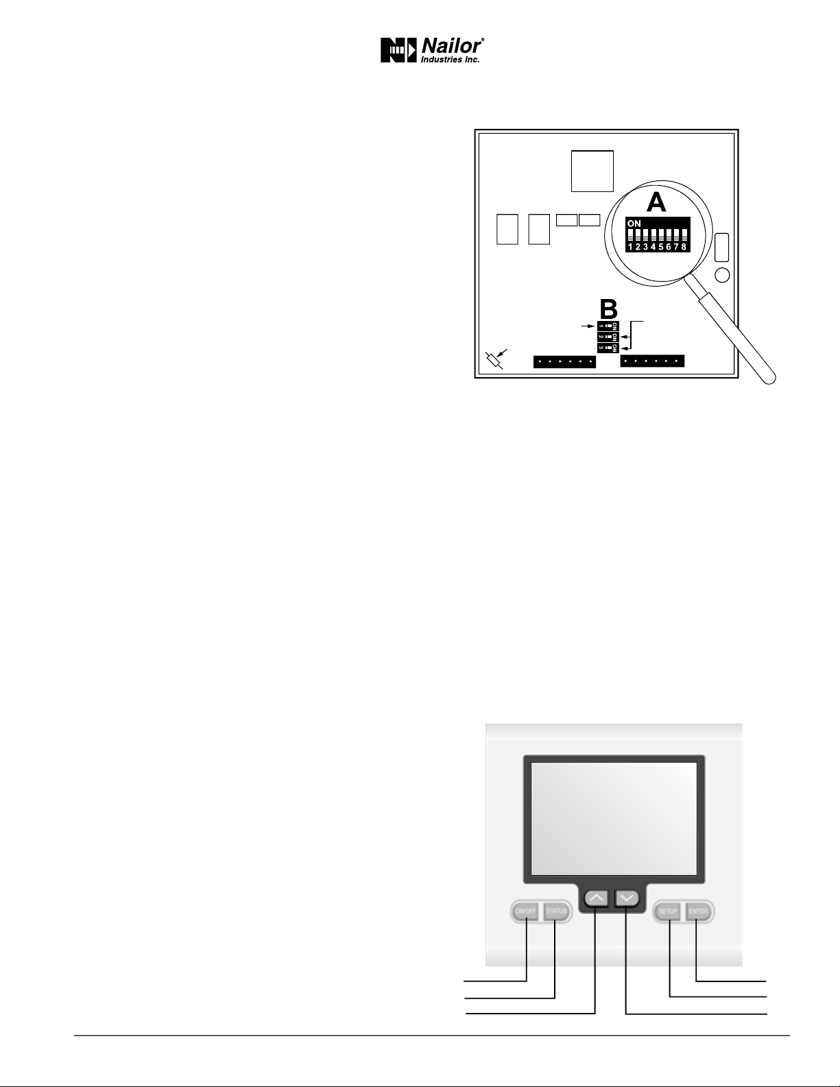
SWITCH FUNCTIONS. . . . . . . . . . . . . . . . . . . . . . . . . . . . . . . . . . . . . . . . . . . . . . . . . . . . . . . 7
KEY FUNCTIONS . . . . . . . . . . . . . . . . . . . . . . . . . . . . . . . . . . . . . . . . . . . . . . . . . . . . . . . . . . 7
SETUP . . . . . . . . . . . . . . . . . . . . . . . . . . . . . . . . . . . . . . . . . . . . . . . . . . . . . . . . . . . . . . . 8-10
Start up. . . . . . . . . . . . . . . . . . . . . . . . . . . . . . . . . . . . . . . . . . . . . . . . . . . . . . . . . . . . . . . . . . . . . . . . . 8
Entering the setup menu . . . . . . . . . . . . . . . . . . . . . . . . . . . . . . . . . . . . . . . . . . . . . . . . . . . . . . . . . . 8
. . . . . . . . . . . . . . . . . . . . . . . . . . . . . . . . . . . . . . . . . . . . . . . 8
. . . . . . . . . . . . . . . . . . . . . . . . . . . . . . . . . . . . . . . . . . . . . . . 8
. . . . . . . . . . . . . . . . . . . . . . . . . . . . . . . . . . . . . . . . . . . . . . . . . . . . . . . . . . . . . 9
. . . . . . . . . . . . . . . . . . . . . . . . . . . . . . . . . . . . . . . . . . . . . . . . . . . . . . . . . . . . 9
. . . . . . . . . . . . . . . . . . . . . . . . . . . . . . . . . . . . . . . . . . . . . . . . . . . . . . . . . . . 9
. . . . . . . . . . . . . . . . . . . . . . . . . . . . . . . . . . . . . . . . . . . . . . . . . . . . . . . . . . . 9
. . . . . . . . . . . . . . . . . . . . . . . . . . . . . . . . . . . . . . . . . . . . . . . . . . . . . . . . 10
. . . . . . . . . . . . . . . . . . . . . . . . . . . . . . . . . . . . . . . . . . . . . . . . . . . . . . . 10
. . . . . . . . . . . . . . . . . . . . . . . . . . . . . . . . . . . . . . . . . . . . . . . . . . . . . 10
. . . . . . . . . . . . . . . . . . . . . . . . . . . . . . . . . . . . . . . . . . 10
Checking thermostat status. . . . . . . . . . . . . . . . . . . . . . . . . . . . . . . . . . . . . . . . . . . . . . . . 11
. . . . . . . . . . . . . . . . . . . . . . . . . . . . . . . . . . . . . . . . . . . . . . . . . 11-12
Changing the Setpoint. . . . . . . . . . . . . . . . . . . . . . . . . . . . . . . . . . . . . . . . . . . . . . . . . . . . . . . . . . . . 11
. . . . . . . . . . . . . . . . . . . . . . . . . . . . . . . . . . . . . . . . . . . . . . . . . . . . . . . . . . . . . . . . . . 11
Call for cooling . . . . . . . . . . . . . . . . . . . . . . . . . . . . . . . . . . . . . . . . . . . . . . . . . . . . . . . . . . . . . . . . . . 12
. . . . . . . . . . . . . . . . . . . . . . . . . . . . . . . . . . . . . . . . . . . . . . . . . . . . . . 12
. . . . . . . . . . . . . . . . . . . . . . . . . . . . . . . . . . . . . . . . . . . . . . . . . . . . . . . . . 12
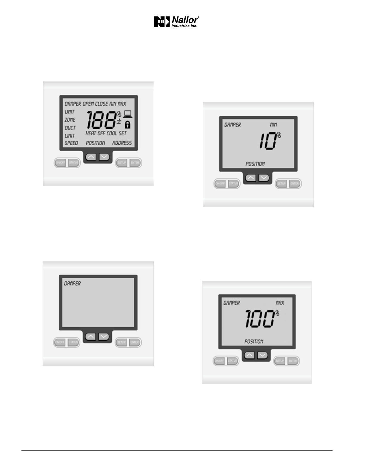
Override to open . . . . . . . . . . . . . . . . . . . . . . . . . . . . . . . . . . . . . . . . . . . . . . . . . . . . . . . . . . . . . . . . 12
Override to close . . . . . . . . . . . . . . . . . . . . . . . . . . . . . . . . . . . . . . . . . . . . . . . . . . . . . . . . . . . . . . . . 12
Canceling the damper override . . . . . . . . . . . . . . . . . . . . . . . . . . . . . . . . . . . . . . . . . . . . . . . . . . . . 12

Installation and Operation Manual ●UNI2-VAV Electronic Thermostat
Nailor reserves the right to change any information concerning product or specification without notice or obligation.
IOM-UNIVAVETINST
Date: 8-2021 Supersedes: NEW 3 of 12
UNI2-VAV ELECTRONIC THERMOSTAT
HOW IT WORKS:
FEATURES:
•
• Selectable Fahrenheit or Celsius display
•
•
•
• Adjustable high and low setpoint limits
•
• Damper override for system balancing
• Assignable unit number
•
• Assignable Modbus address
• Locking keyboard
• Backlit LCD display
• Remote indoor sensor terminals
•
• Unit number
• Zone number
• Duct temperature
•

Installation and Operation Manual ●UNI2-VAV Electronic Thermostat
Nailor reserves the right to change any information concerning product or specification without notice or obligation.Nailor reserves the right to change any information concerning product or specification without notice or obligation.
IOM-UNIVAVETINST
Date: 8-2021 Supersedes: NEW 4 of 12
The UNI2-VAV electronic thermostat
HOW IT WORKS:
°
°
SPECIFICATIONS
UNI2-VAV Electronic Thermostat specifi ca ons are subject to change without no ce.
Input voltage:
° to 122°F
Accuracy: °°F
TERMINAL DESIGNATIONS
Thermostat Subbase
The thermostat has dedicated screw terminals located on the subbase to facilitate ease of wiring to the actuator board mounted
MODBUS
MODBUS
HEATING RELAY
COOLING RELAY
DUCT SENSOR
DUCT SENDOR
REMOTE SENSOR
REMOTE SENSOR
24 VAC (COMMON)
24 VAC (HOT)
POWER OPEN
POWER CLOSE
Temperature sensor: 10K NTC Type II
Control range: 36°F to 96°F
Backlight: Blue Electro Luminescent
Backlight life:
Approvals:
Dimensions: 4.0"""D

Installation and Operation Manual ●UNI2-VAV Electronic Thermostat
Nailor reserves the right to change any information concerning product or specification without notice or obligation.
IOM-UNIVAVETINST
Date: 8-2021 Supersedes: NEW 5 of 12
SYSTEM WIRING DIAGRAMS
DAMPER OPEN (24 VAC)
DAMPER CLOSED (24 VAC)
CALL FOR HEAT (24 VAC)
24 VAC POWER (HOT)
24 VAC POWER (COM.)
DUCT SENSOR
DUCT SENSOR
CALL FOR COOL (24 VAC)
THERMOSTAT
AUTO CHANGEOVER
SPACE THERMOSTAT RED LED
INDICATES
A CALL FOR
HEATING
GREEN LED
INDICATES
A CALL FOR
COOLING
ACTUATOR
BOARD
DAMPER OR DIFFUSER
ACTUATOR
OPEN
CLOSED
COM.
DS
DS
OPEN
CLOSED
COM.
90 SECOND TIMING
90˚STROKE
44 Ib.-in.
2VA
DUCT SENSOR
(10K OHMS @77˚)
OPTIONAL
AUX HEAT
CONTACTS
REMOVE FACTORY
JUMPER IF USED
WIRE TO
OPTIONAL
SLAVE
DAMPER
24 VAC
POWER
Temperature sensor: 10K NTC Type II
Control range: 36°F to 96°F
Backlight: Blue Electro Luminescent
Backlight life:
Approvals:
Dimensions: 4.0"""D
Typical Zone Control System
DAMPER OPEN (24 VAC)
DAMPER CLOSED (24 VAC)
CALL FOR HEAT (24 VAC)
24 VAC POWER (HOT)
24 VAC POWER (COM.)
DUCT SENSOR
DUCT SENSOR
CALL FOR COOL (24 VAC)
THERMOSTAT
AUTO CHANGEOVER
SPACE THERMOSTAT RED LED
INDICATES
A CALL FOR
HEATING
GREEN LED
INDICATES
A CALL FOR
COOLING
ACTUATOR
BOARD
DAMPER OR DIFFUSER
ACTUATOR
OPEN
CLOSED
COM.
DS
DS
OPEN
CLOSED
COM.
90 SECOND TIMING
90˚STROKE
44 Ib.-in.
2VA
DUCT SENSOR
(10K OHMS @77˚)
WIRE TO
ZONE PANEL TERMINAL
WIRE TO
OPTIONAL
SLAVE
DAMPER
C R Y W

Installation and Operation Manual ●UNI2-VAV Electronic Thermostat
Nailor reserves the right to change any information concerning product or specification without notice or obligation.Nailor reserves the right to change any information concerning product or specification without notice or obligation.
IOM-UNIVAVETINST
Date: 8-2021 Supersedes: NEW 6 of 12
SUBBASE
Removing the thermostat from the subbase
connector pins.
The top of the thermostat is hinged to the subbase and will
release when rotated upward.
the grooves at the top of the thermostat.
thermostat with the slots in the top of the subbase. Allow
connector pins are fully seated into the terminal blocks.
the ambient room temperature. Do not install the thermostat in
or other areas not typical of the temperature of the room.
travel down cavity walls and enter the back of the thermostat
through the control wire holes in the wall. It is important to seal
temperature sensor.
Pull the control wires through the large opening in the
thermostat subbase then level and mount the subbase on
the wall using the supplied anchors and screws. Do not over-
to the terminal blocks.
land each wire to its dedicated terminal. Check to see that all
wires are landed correctly and dressed properly to prevent any
shorts.

Installation and Operation Manual ●UNI2-VAV Electronic Thermostat
Nailor reserves the right to change any information concerning product or specification without notice or obligation.
IOM-UNIVAVETINST
Date: 8-2021 Supersedes: NEW 7 of 12
SWITCH FUNCTIONS
(A) SWITCH 1
Do not set Switch 1 in
(A) SWITCH 2 displays the space temperature and setpoint
(A) SWITCH 3
(A) SWITCH 4 & 5
(A) SWITCH 6 Switch 6 is used to display or hide the Heat and
Cool
Heat and Cool.
(A) SWITCH 7
the set temperature is displayed.
(A) SWITCH 8
(B) SWITCH 1
Switch 1 should remain OFF for Modbus. It is only used as an end
(B) SWITCH 2 & 3
is OFF.
ON.
KEY FUNCTIONS
STATUS KEY
UP
DOWN
KEYS - These keys are used to increase
or decrease the setpoint as well as change thermostat setup
values.
SETUP KEY - This key allows the installer to toggle through the
thermostat setup menu.
ENTER KEY
the setup menu.
MODBUS
SENSOR
INTERNAL OR
REMOTE SENSOR
SWITCHES
ON/OFF
STATUS
UP
ENTER
SETUP
DOWN

Installation and Operation Manual ●UNI2-VAV Electronic Thermostat
Nailor reserves the right to change any information concerning product or specification without notice or obligation.Nailor reserves the right to change any information concerning product or specification without notice or obligation.
IOM-UNIVAVETINST
Date: 8-2021 Supersedes: NEW 8 of 12
Press the SETUP key again and the LCD will display the
Figure 3
Press the SETUP
Figure 4
Helpful Hint:
balancing when no manual balancing dampers have been
installed.
SETUP
Startup
Replace the thermostat on the subbase and apply 24 Volts
Figure 1
Entering the setup menu
Press and hold the SETUP
Figure 2

Installation and Operation Manual ●UNI2-VAV Electronic Thermostat
Nailor reserves the right to change any information concerning product or specification without notice or obligation.
IOM-UNIVAVETINST
Date: 8-2021 Supersedes: NEW 9 of 12
Press the SETUP
Figure 7
Press the SETUP key again and the LCD will display the cooling
Figure 8
The SETUP key again and the LCD will display the word UNIT.
The factory default is 00. This number can be used to assign the
Figure 5
Press the SETUP key again and the LCD will display the word
ZONE. The factory default is 00. This number can be used to
Figure 6
Helpful Hint:
ENTER
SETUP key
SETUP

Installation and Operation Manual ●UNI2-VAV Electronic Thermostat
Nailor reserves the right to change any information concerning product or specification without notice or obligation.Nailor reserves the right to change any information concerning product or specification without notice or obligation.
IOM-UNIVAVETINST
Date: 8-2021 Supersedes: NEW 10 of 12
Press the SETUP key again and the LCD will display the
Figure 11
Press the ENTER key again and the thermostat will save the
hold the SETUP
ENTER
setup menu. Remove the thermostat from the subbase and set
Figure 12
Press the SETUP key again and the LCD will display the actuator
takes the actuator to drive the damper blade fully open or fully
be used with a variety of 24 Volt actuators. If you are unsure
Figure 9
Press the SETUP key again and the LCD will display the Modbus
address. The factory default is 01.
Figure 10
FIGURE 11
l

Installation and Operation Manual ●UNI2-VAV Electronic Thermostat
Nailor reserves the right to change any information concerning product or specification without notice or obligation.
IOM-UNIVAVETINST
Date: 8-2021 Supersedes: NEW 11 of 12
CHECKING THERMOSTAT STATUS
STATUS key and
UNIT - Displays the HVAC unit number assigned to the
thermostat
ZONE
DUCT - Displays the duct temperature
POSITION
THERMOSTAT OPERATION
The thermostat is designed to provide accurate but simple
limits and review the status points by pressing the STATUS key
Figure 13
Changing the Setpoint
display the word SET. The setpoint then can be changed within
Figure 14
HEAT will be
Figure 15

Installation and Operation Manual ●UNI2-VAV Electronic Thermostat
Nailor reserves the right to change any information concerning product or specification without notice or obligation.Nailor reserves the right to change any information concerning product or specification without notice or obligation.
IOM-UNIVAVETINST
Date: 8-2021 Supersedes: NEW 12 of 12
Call for cooling
COOL will be
Figure 16
ADVANCED FUNCTIONS
SETUP
word DAMPER
Figure 17
Override to open
LCD and then press the ENTER key. The damper will drive open
Figure 18
Override to close
the LCD and then press the ENTER key. The damper will drive
Figure 19
Canceling the damper override
the override must be canceled. Press and hold the SETUP key
is displayed and then press the ENTER key. The thermostat will
Other manuals for UNI2-VAV
1
Table of contents
Other Nailor Thermostat manuals