NAIM N-VI User manual

OWNERS MANUAL
n-Vi Home Theatre System
ENGLISH
DEUTSCH
FRANÇAIS
ITALIANO

SAFETY INSTRUCTIONS
In order to comply with current European safety regulations
it is essential that the Naim loudspeaker connectors supplied
with amplifiers and loudspeakers are used.
Do not under any circumstances allow anyone to modify your
Naim equipment without first checking with the factory, your
retailer, or your distributor. Unauthorised modifications will
invalidate your guarantee.
Equipment must not be exposed to dripping or splashing and
no objects filled with liquid, such as vases, should be placed
on the equipment.
For your own safety do not under any circumstances open
Naim equipment without first disconnecting it from the mains.
Warning: an apparatus with CLASS I construction shall be
connected to a mains socket outlet with a protective earthing
connection.
Where the mains plug or an appliance coupler is used as
the disconnect device, the disconnect device shall remain
readily operable. To disconnect the equipment from the mains
remove the mains plug from the mains outlet.
The following label is attached to all mains powered
equipment:
NOTE
This equipment has been tested and found to comply with the
relevant EMC and Safety Standards, and, where applicable,
also complies with the limits for a class B digital device,
pursuant to Part 15 of the FCC Rules.
These limits are designed to provide reasonable protection
against harmful interference in a residential installation.
This equipment generates, uses and can radiate radio
frequency and, if not installed and used in accordance
with the instructions, may cause harmful interference to
radio communications. However, there is no guarantee that
interference will not occur in a particular installation. If
this equipment does cause harmful interference to radio or
television reception, which can be determined by turning
off and on, the user is encouraged to try to correct the
interference by one or more of the following measures:
• Reorient or relocate the receiving antenna.
• Increase the separation between the equipment and the
receiver.
• Connect the equipment into an outlet on a circuit different
from that to which the receiver is connected.
• Consult your Naim retailer or an experienced radio/TV
technician for help.
WARNING
THIS APPARATUS
MUST BE EARTHED
Contents
Page
Section
E1 1 Connections
2 Mains Power Connection
E2 3 General Installation
E3 4 Product Introduction and Contents
E4 5 Connections
E6 6 Control and Setup
E9 7 On Screen Setup
E14 8 Front Panel Setup
E16 9 Operation
E20 10 Video Formats Explained
E21 11 DAB/FM Tuner
E22 12 System Connections
E23 13 Trouble-shooting
E25 14 Specification
E25 Licence Acknowledgements and Declaration of
Conformity

E1
1 Connections
It is important for both safety and performance that
the standard cables supplied are not modified.
1.1 Interconnect Cables
If options are available with your equipment and installation,
DIN interconnect sockets should be used in preference to RCA
Phono sockets. One end of each Naim interconnect cable is
marked with a band to establish its correct orientation. The
band denotes the end that connects to the signal source.
Interconnect plugs and sockets should be kept clean and free
from corrosion. The easiest way to clean them is to switch off
the equipment, pull the plugs out of their sockets, and push
them back in again. Contact cleaners and “enhancers” should
not be used as the film they deposit may degrade the sound.
1.2 Loudspeaker Cables
Although any high quality loudspeaker cable is suitable, we
recommend that Naim loudspeaker cable is used. Naim
loudspeaker cable is directional and should be oriented so
that the printed arrow points towards the speakers. The
loudspeaker connectors supplied are designed to comply with
European safety legislation and must be used.
Contact your local retailer or distributor for further advice on
loudspeaker cables and connectors.
2 Mains Power Connection
Where fused plugs are used 13 amp fuses should
be fitted. Fuses of a lower rating will fail after
a period of use. Do not wire voltage dependent
resistors or noise suppressors into mains plugs.
They degrade the mains supply and the sound.
2.1 Mains Plug Wiring
In some territories a mains plug may need to be fitted to the
supplied mains lead. As the colours of the wires in the mains
lead may not correspond with the coloured markings identifying
the terminals in the plug proceed as follows:
The wire which is coloured
GREEN-AND-YELLOW
must be
connected to the terminal in the plug which is marked by the
letter
E
or by the safety earth symbol or coloured
GREEN
or
GREEN
and
YELLOW
.
naim
Naim Audio products are conceived with performance as the top priority.
Careful installation will help ensure that their full potential is achieved.
This manual covers the n-Vi all-in-one home theatre system. It begins
with some general installation notes and statutory safety warnings.
More product specific information begins in Section 4.
The wire which is coloured
BLUE
must be connected to the
terminal in the plug which is marked with the letter
N
or
coloured
BLACK
.
The wire which is coloured
BROWN
must be connected to
the terminal in the plug which is marked with the letter
L
or
coloured
RED
.
2.2 Equipment Fuses
Mains powered Naim Audio equipment is fitted with a mains
input fuse on the rear panel adjacent to the mains input
socket. Replace it if necessary only with the spare fuse
supplied or with identical fuses. Repeated failure of this
fuse points to an equipment or system fault that should be
investigated by your retailer or at the factory by Naim itself.
2.3 Non-rewirable Mains Plugs
If a non-rewirable plug is cut from a mains lead (for whatever
purpose) the plug MUST be disposed of in a way to render it
totally useless. Considerable shock hazard exists if the cut-off
plug is inserted into a mains outlet.
2.4 Mains Circuits and Cables
A hi-fi system usually shares a mains circuit with other
household equipment some of which can cause distortion of
the mains waveform. A separate mains circuit (ideally with a
30 or 45 Amp rating) may reduce such distortion and improve
system performance. Advice on the installation of a separate
mains circuit should be sought from a qualified electrician.
Do not substitute alternative mains leads and plugs to
those supplied. They are selected to offer the best possible
performance.
Introduction

E2
3 General Installation
Naim equipment is designed to offer the finest
performance possible avoiding compromise
wherever practical. This can lead to circumstances
that may be unfamiliar. The notes that follow
contain advice specifically related to Naim
equipment as well as more general warnings about
the use of domestic audio products. Please read
them carefully.
3.1 Siting The Equipment
Some Naim equipment is extremely heavy. Check the weight of
the equipment prior to lifting and if necessary use more than
one person so that it can be moved safely. Ensure that your
equipment rack or table can easily support the weight and is
stable.
3.2 Switching On
Always use the switch on the product rather than a mains
outlet switch to switch the product on.
A “thump” may be heard from the loudspeakers as power
amplifiers are switched on. This is normal, will not cause
any loudspeaker damage and does not point to any fault
or problem. A mild “pop” may also be heard shortly after
equipment is switched off.
3.3 Running In
Naim equipment takes a considerable time to run in before
it performs at its best. The duration varies, but under some
conditions the sound may continue to improve for over a
month. Better and more consistent performance will be
achieved if the system is left switched on for long periods. It is
worth remembering however that equipment left connected to
the mains can be damaged by lightning.
3.4 Radio Interference
In some circumstances, depending on where you live and the
earthing arrangements in your home, you may experience
radio frequency interference. Controls on broadcasting in some
territories allow very high levels of radio frequency radiation
and both the choice and exact siting of equipment may be
critical. Susceptibility to radio frequency interference is related
to the wide internal bandwidth necessary for high sound
quality. A radio frequency filter kit is available for some Naim
equipment but sound quality will be progressively compromised
as more elements of the kit are fitted. In situations of extreme
radio interference Naim equipment may be unsuitable.
3.5 Lightning Precautions
Your Naim hi-fi system can be damaged by lightning and should
be turned off and disconnected from the mains when there is
risk of lightning strike. For complete protection all mains plugs
and any aerial cables should be disconnected when not in use.
3.6 Problems?
Consumer protection varies from country to country. In
most territories a retailer must be prepared to take back
any equipment he has sold if it cannot be made to work
satisfactorily. A problem may be due to a fault in the system
or its installation so it is essential to make full use of your
dealer’s diagnostic skills. Please contact your local distributor,
or Naim Audio directly, if any difficulties cannot be resolved.
Some Naim equipment is made in special versions for
different territories and this makes it impracticable to arrange
international guarantees. Please establish the local guarantee
arrangements with your retailer. Contact Naim Audio directly
for help and advice if necessary.
3.7 Service and Updates
It is essential that repairs and updates are only carried out by
an authorised Naim retailer or at the factory by Naim itself.
Many components are custom made, tested or matched and
appropriate replacements are often unobtainable from other
sources.
Direct contact to Naim for service or update information should
be made initially through Customer Services:
Tel:
+44 (0)1722 426600
Email:
Please quote the product serial number (found on its rear
panel) in all correspondence.
naim Introduction

E3
n-Vi
4 Product Introduction and Contents
This manual covers installation and operation of the n-Vi all-in-one home theatre
system. With the n-Vi, combining DVD, home theatre and genuine high-end hi-fi
music reproduction is simple. The n-Vi includes everything you need in one box:
DVD and CD player, AV Processor, audio preamplifier, five channel audio power
amplifier and an optional DAB*/FM tuner. Just add speakers and a display.
The n-Vi is fundamentally straightforward in use, however its versatility and
comprehensive functionality mean that a little time spent reading will help ensure
problem-free setup and use.
The n-Vi should be installed on a dedicated equipment stand intended for the
purpose. Care should be taken to ensure that it is level. Do not switch on the n-Vi
until all input and output connections are made. Make sure you are familiar with
the safety warnings and general installation advice contained within the first part
of this manual.
Following this introduction, the manual is divided into the following sections.
Contents
5. Connections
5.1 Signal Inputs
5.2 Control Inputs
5.3 Video Outputs
5.4 Audio Outputs
5.5 Speaker Outputs
5.6 Control Outputs
5.7 Rear Panel and Connections
6. Control and Setup
6.1 The User Interface
6.2 The Narcom DV Handset
6.3 Recommended Initial Setup
7. On Screen Setup
7.1 DVD Playback Setup
7.2 System Setup
7.3 Video Setup
7.4 Progressive Scan Setup
7.5 Audio Setup
7.6 Speaker Setup
7.7 Parental Control Setup
7.8 Exit On Screen Setup
8. Front Panel Setup
8.1 Video System and Format Selection
8.2 Speaker, Input and Audio Setup
8.3 Miscellaneous Setup
8.4 Clock Setup (requires DAB/FM Module)
8.5 Alarm Setup (requires DAB/FM Module)
8.6 Exit Front Panel Setup
9. Operation
9.1 Input Selection and Volume Control
9.2 Playback Control
9.3 Playback Options
9.4 Accessory Functions
9.5 Decode Modes - Selection and Availability
9.6 Channel Schemes and Speakers
9.7 Surround Encoding Technology Explained
10. Video Formats Explained
10.1 Interlaced and Progressive Scan Video
10.2 Video Interface Formats
11. DAB*/FM Tuner
11.1 DAB Menu and Operation
11.2 FM Menu and Operation
12. System Connections
12.1 n-Vi with NAC 252, Supercap and NAP 250
13. Trouble-shooting
13.1 Video and Disc Playback
13.2 Audio
14. Specification
Introduction
*
DAB radio broadcasts are not available in all territories.

E4
5 Connections
Once the n-Vi is positioned on a rack or furniture
unit it can be connected to a mains supply. Use the
mains cable supplied. Do not switch on the n-Vi until
all audio, video and control connections have been
made.
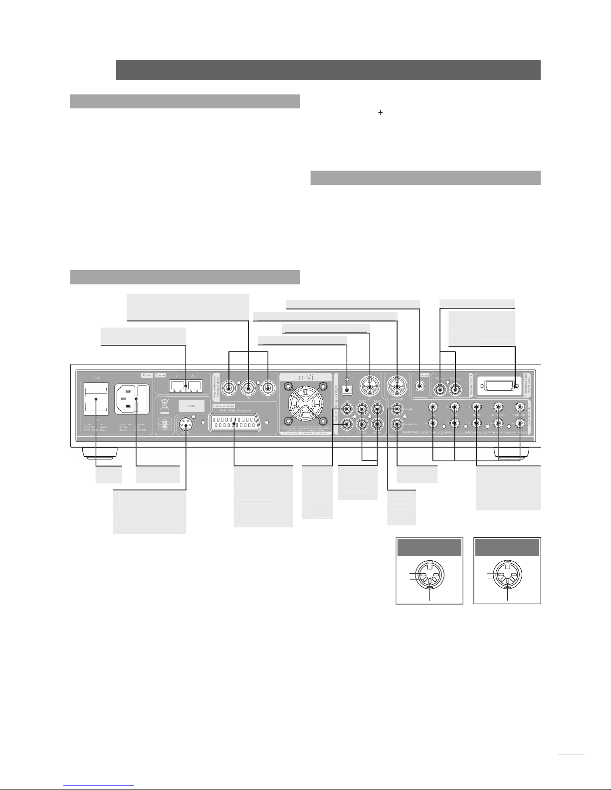
The appropriate input and output connections will depend on
the type of system the n-Vi is to be used in. An Illustration of
the n-Vi input and output connections can be found on the page
opposite while a diagram illustrating the n-Vi integrated with an
existing stereo system can be found in Section 12.
It is important that high quality cable is used for signal and
speaker connections. Your local retailer or distributor will be
able to offer advice.
5.1 Signal Inputs
The n-Vi can accept three digital and four analogue audio
inputs for the connection of external source equipment. Two
of the digital inputs are connected via RCA-phono sockets and
one via an optical connector. Two of the analogue inputs are
connected via RCA-phono socket pairs and one via a 5-pin DIN
socket. One RCA-phono analogue input socket pair (Input A3)
is duplicated on the n-Vi front panel with a stereo 3.5mm jack
socket. This socket is intended for the temporary connection of
portable music players. Insertion of a plug into the front panel
jack socket will automatically switch the n-Vi to this input. If any
equipment is simultaneously connected to the rear panel A3
input sockets its audio signal will be mixed with the front panel
signal. Removal of the front panel input plug will automatically
switch the n-Vi to the previously selected input.
If the n-Vi has a DAB/FM Radio Upgrade fitted it will also have
an F-Type radio aerial input socket on the rear panel. Indoor
aerials can be used although best results are likely to be
obtained from roof aerials mounted as high as posssible. Use
high quality 75Ω aerial cable for connecting aerials.
Use of an aerial preamplifier may disturb the FM muting
operation of the tuner and may cause other problems. Such
preamplifiers should therefore only be used as a last resort.
An aerial combining unit may be used to combine signals from
separate DAB and FM aerials. Your local retailer or distributor
will be able to offer specific advice on local DAB and FM signal
reception.
For details of all signal input sockets see Diagram 5.7.
5.2 Control Inputs
The n-Vi provides control inputs that enable it to be integrated
with remote handset (RC5) signal repeaters and optionally
with multi-room equipment control systems. The RC5 signal is
connected through a single RCA-phono socket and the optional
multi-room control input connected through an RJ45 socket.
For details of all control input sockets see Diagram 5.7.
5.3 Video Outputs
The n-Vi can provide video outputs in a number of different
formats on a variety of connection sockets. Each format
and socket is appropriate for alternative display types - TV,
CRT Monitor, TFT Monitor, Plasma, Projector, etc. - and it is
important for the best picture quality that the appropriate
socket is used. Table 5.3 lists, in order of preference,
connection formats for any display device. Select, from the
connection options available on your display, the one nearest
the top of the list. For details of all video
output sockets see Diagram 5.7.
5.4 Audio Outputs
The n-Vi provides one stereo analogue audio
output via a 5-pin DIN socket and one digital
audio output via a single RCA-phono socket.
These sockets enable the n-Vi to be connected
to an external audio preamplifier or alternative
multi-channel decoder respectively. In the
case of multi-channel programme material,
the signal present on the analogue output is
the front left and right channels. Analogue
programme material input to the n-Vi from an
external source is not available from the digital
output. The n-Vi also provides one analogue
subwoofer output via a single RCA-phono
socket. For details of all audio signal output
sockets see Diagram 5.7.
n-Vi Connections
Connection
Connection
Cable/Socket
Notes
Format
Type
DVi
DVi
Digital Progressive Scan
RGB
3 x BNC
Analogue Progressive Scan
YPbPr
3 x BNC
Analogue Progressive Scan
RGB
SCART
Analogue Interlaced
YPbPr
SCART
Analogue Interlaced
S-Video
4-pin mini DIN
Analogue Interlaced
Composite
SCART
Analogue Interlaced
Note:
Section 10 carries an explanation of the video formats
listed.
Note:
RGB progressive scan output is disabled when replaying
Macrovision encoded material.
Rank
Order
First
Second
Third
Fourth
Fifth
Sixth
Seventh
Table 5.3
Preferred Video Connections

E5
n-Vi
5.7 Rear Panel and Connections
Optional multi-room
comms input and output
Mains input
and fuse
Power
switch
S-Video output. Use
only if higher quality
alternatives not
supported by display.
See Table 5.3
SCART Video
output. Use only
if higher quality
alternatives not
supported by
display. See
Table 5.3
RGB and YPbPr Video outputs. Use
only if higher quality alternatives not
supported by display. See Table 5.3
Analogue audio input one
Digital audio optical input
Analogue audio output. Front left and right
Optional DAB and FM Radio aerial input
RC5 input and output
DVI Video output.
Use for highest
quality if supported
by display.
by display.
Digital
audio
coaxial
inputs
two and
three
Analogue
audio
inputs two
and three
Digital
audio
coaxial
output
Subwoofer
output
Left front, right
front, centre, left
surround and
right surround
speaker outputs
negative
DIN Audio Input
ch1
(left)
ch2
ch2
ch2
(right)
negative
DIN Audio Output
ch1
(left)
ch2
ch2
ch2
(right)
Connections
5.5 Speaker Outputs
The n-Vi provides five speaker output sockets each rated at
90 watts into 4Ω. The five speaker outputs are intended to
be connected to the front left, front right, centre, surround
left and surround right speakers. In order to comply with
European safety legislation speakers should be connected
using the supplied Naim Audio n-Vi speaker plugs only. Naim
Audio speaker cable is recommended although alternatives are
possible. Your local retailer or distributor will be able to offer
advice.
When connecting speakers ensure that each positive pin -
identified by a “
+
” mark on the side of the connector body - is
always inserted to the positive output sockets. Also ensure that
the connections at the speaker are connected with the same
polarity. For details of the speaker output sockets see Diagram
5.7.
5.6 Control Outputs
The n-Vi provides control outputs that enable it to be integrated
with remote handset signal (RC5) repeaters and optionally
with multi-room equipment control systems. The RC5 output is
connected via a single RCA-phono socket and the optional multi-
room control output is connected via an RJ45 socket. For more
detail on connection to the control input sockets see Diagram
5.7.

E6
n-Vi Control and Setup
6 Control and Setup
Once all the input and output connections are made
the n-Vi can be set up. Although the n-Vi can be
set up and controlled from its front panel, many
parameters are best set from the listening position,
so use of the NARCOM DV handset is recommended.
When initially switched on from the rear panel, the n-Vi will,
after a short delay, enter standby mode. Standby is indicated
by an illuminated front panel
standby
button. To wake the n-Vi
press the handset
standby
key or front panel
standby
button.
The n-Vi will wake in either the factory default state, if it is
previously unused, or in the state in which it was last shut
down. Once the n-Vi is switched on, the video display and any
other associated equipment should also be switched on.
Note:
The n-Vi can be returned to its factory default settings by
pressing and holding the handset clear key with no disc loaded.
6.1 The User Interface
The n-Vi can generally be operated from its front panel or
from the
Narcom DV
remote handset in either
AV
or
DVD
modes. The On Screen Display and Front Panel Display provide
operational feedback.
Note:
If nothing is displayed when the n-Vi and display are first
switched on some Front Panel Setup video output options may
need to be changed. See Section 8.1.
The n-Vi has two setup routines.
On Screen Setup
(Section
7) and
Front Panel Setup
(Section 8).
On Screen Setup
configures parameters that apply to system-wide setup, DVD
playback and video display.
Note:
Some On Screen Setup parameters can also be accessed
and adjusted via Front Panel Setup.
6.1.1 On Screen Setup
During
On Screen Setup
, all functions are accessed via a
cascading menu system with the handset
5
(up),
6
(down),
3
(left),
4
(right) and
ok
keys. To navigate through the top
level and second level menus use the handset
up (
5
)
and
down (
6
)
keys. To confirm a selection press the
ok
key. To
return to the previous menu without making a selection or a
change use the
rtn
(return) key, or press
setup
to exit from the
setup menus.
To navigate through the third level menu use the handset
left
(
3
)
and
right (
4
)
keys. To increase or decrease a parameter
value use the
up (
5
)
and
down (
6
)
keys respectively. Use the
ok
key to confirm the setting. To return to the previous menu
without making a selection or a change use the
rtn
(return) key.
Press
setup
to exit from the setup menus.
Note:
The handset clear key can be used at any time to clear any
On Screen Display.
6.1.2 Front Panel Setup, Controls and Display
During
Front Panel Setup
, functions are accessed via a
cascading menu system with front panel
-vol
,
prev
,
input
,
play
and
stop
buttons providing menu
navigation
and
ok
commands. These buttons are illuminated in setup mode. In
normal mode the buttons revert to operating as described
below and illustrated in the diagram.
Note:
The handset navigation keys can also be used for Front
Panel setup.
standby:
Switches the n-Vi in and out of standby mode.
-vol:
Decreases volume
vol+:
Increases volume
input:
Selects next signal input
mode:
Selects next AV decode mode
stop:
Stops playback. Press while stopped opens drawer.
play:
Starts playback. Press while in play pauses play.
Press while drawer open closes drawer.
prev:
Selects previous chapter or track.
next:
Selects next chapter or track.
The n-Vi front panel display provides feedback of volume level,
input selection, decode mode, channel scheme and, if the
optional DAB/FM tuner is fitted, radio station identity and data.
The front panel display will switch off after two minutes of
inactivity.
Player
transport
transport
Standby
Standby
Volume
adjustment
adjustment
adjustment
adjustment
Signal input
and decode
mode selection
Channel
scheme
Decode
mode
Output volume
Output volume
Diagram 6.1.2
Front panel controls and display.
Selected
input
input

E7
6.1.3 Front Panel Channel Scheme Icon
The term “channel scheme” describes the array of speakers in
use. The channel scheme operating at any time is linked to the
input signal, speaker setup and decode mode and is illustrated
on the n-Vi front panel display by an icon in the bottom right
hand corner (See Diagram 6.1.3). The icon changes as different
input signals and decode modes are selected (either manually
or automatically) or speaker setups are specified.
The icon represents a listening room with front left, centre,
front right, surround left, surround right and subwoofer
speakers. Each speaker element within the icon shows or hides
to denote presence in the speaker setup, grows or shrinks to
reflect “large” or “small” specification (see Paragraph 7.6.1),
or is filled or empty to denote its presence or absence in the
channel scheme.
n-Vi Control and Setup
Left Centre Right
Left Centre Right
Left Right
Surround Surround
Subwoofer
Diagram 6.1.3
Front panel display channel scheme icon
6.2 The NARCOM DV Handset
The NARCOM DV is a dedicated remote handset for the n-Vi,
DVD5 and AV2. It will also operate the core functions of a Naim
CD player, preamplifier or
integrated amplifier.
The
System Component
keys switch the handset
mode of operation as
appropriate to different
components (preamplifier,
CD, AV, DVD, n-Vi).
pre:
Switches the action of
appropriate keys to operate
a preamplifier or integrated
amplifier.
cd:
Switches the action of
appropriate keys to operate
a CD player.
av:
Switches the action
of appropriate keys to
operate an AV2 audio-visual
processor or n-Vi system
(including DAB/FM module).
dvd:
Switches the action of
appropriate keys to operate
a DVD player or n-Vi system
(including DAB/FM module).
Note:
An audio CD played
in a DVD/n-Vi player would
still be controlled with the
handset in DVD mode.
Depending on the System Component setting and, in some
cases signal input selected, the
Numeric
keys select disc titles,
groups, tracks or chapters or tuner presets.
Note:
To select DVD titles or DVD-A groups place a leading zero
before the required title or group number.
The twin sets of
Volume
and
Mute
keys remain available to
either an AV processor (or n-Vi) or preamplifier regardless of the
setting of the System Component keys.
The
Player Transport
keys will switch between CD and DVD
player operation depending on the
System Component
key
selection. If preamplifier or AV is selected the Player Transport
keys will operate the last component type selected.
Standby
Standby
System
component
keys
keys
Volume
and mute
OSD menu
interface
n-Vi
Functions
Player
transport
transport
n-Vi
Functions
Numeric keys
Numeric keys
Left Right
Left Right
Example of a channel
scheme icon illustrating
a 5.1 system with large
front, centre and surround
speakers and a subwoofer.
Example of a channel
scheme icon illustrating a
4.1 system with large front
speakers, a subwoofer and
inactive small surround
speakers.
Note:
As a stereo signal has
no native subwoofer content
Bass Mix has been enabled
to generate subwoofer
information.
Subwoofer
Left Right
Surround Surround

E8
n-Vi Control and Setup
6.3 Recommended Initial Setup
The n-Vi incorporates numerous features and facilities, many
of which may initially be left at their default settings until later
preferences have been established.
Six setup stages are however necessary to establish a basic
setup for satisfactory video and multi-channel audio playback of
audio and audio-visual programme material. These stages, with
their owner’s manual section numbers, are listed below. Each
is also accompanied in the body of the owner’s manual by an
exclamation mark graphic:
6.3.1 Initial Setup Stages
Stage One: Video System and Output Format
Section 7.3.1 or Section 8.1
Setting the Video System and Output Format ensures that the
n-Vi is configured correctly for the display connected. Can be
set from either the On Screen or Front Panel menus.
Note:
The default setting is auto.
Stage Two: Aspect Ratio
Section 7.3.6
Sets the video output aspect ratio appropriately for the display
connected.
Note:
The default setting is 16:9.
Stage Three: Colour Format
Section 7.4.1
Sets the video output colour format (RGB, YPbPr) appropriately
for the display connected.
Note:
The default setting is YPbPr.
Stage Four: Speaker Size
Section 7.6.1 or Section 8.2.1
Defines the size of each speaker (small, large or none)
connected to the n-Vi.
Note:
The default setting is 5.1 with large speakers.
Stage Five: Speaker Distance
Section 7.6.3 or Section 8.2.2
Defines the distance of each speaker from the listening
position.
Note:
The default setting is 0.
Stage Six: Speaker Levels
Section 7.6.5 or Section 8.2.3
Sets the relative volume level of each speaker in the system.
Note:
The default setting is 0.
!

E9
n-Vi On Screen Setup
7 On Screen Setup
On Screen Setup configures parameters that apply
to system-wide setup, DVD playback and video
display.
To begin the setup procedure insert a DVD and, after waiting for
the n-Vi to read the disc contents, press the remote handset
setup
key. The top level setup menu will be displayed.
Note:
If nothing is displayed when the n-Vi and display are first
switched on some Front Panel Setup video output options may
need to be changed. See Section 8.1.
The top level setup menu provides access to
DVD Playback,
System Setup, Video Setup, Progressive Scan Video Setup,
Audio Setup
and
Parental Control
options.
Note:
On Screen Setup help text can be accessed by pressing the
handset menu key.
7.1 DVD Playback Setup
Selection of
DVD Playback
from the top level menu generates
a second level menu comprising the options described and
illustrated below. The availability of some options in the second
level menu is dependent on the content of the DVD.
7.1.1 Audio Track
Enables the selection of alternative DVD audio tracks if any are
present on the disc. The alternatives may include sound-track
languages and audio encoding format (Dolby*, DTS, etc.). If no
alternative is available no options will be displayed. The disc
must be playing for audio track selection to be available.
Note:
Audio tracks can also be directly selected during playback by
pressing the handset audio key. Not all discs offer direct selection.
7.1.2 Camera Angle
Enables the selection of alternative camera angles if any are
present on the disc. If no alternative is available no options
will be displayed. The disc must be playing for camera angle
options to be available.
Note:
Camera angles can also be directly selected during playback
by pressing the handset angle key.
7.1.3 Subtitle
Enables the display and selection of alternative DVD subtitles
if any are present on the disc. If no alternative is available no
options will be displayed. The disc must be playing for subtitle
options to be available.
Note:
Subtitles can also be directly selected during playback by
pressing the handset subt key.
7.1.4 DVD Auto Play
Sets the n-Vi to begin playback as soon as the drawer is
closed. Select from
on
or
off
.
Note:
Closing the drawer with the front panel stop button overides
Auto Play. The n-Vi will remain stopped.
7.1.5 Subtitle Preference
Selects the preferred subtitle language. When subtitles are
switched on from either the handset
subt
button or from the
n-Vi menu the subtitle preference language will be shown
if ‘preference’ is selected. If the preferred language is not
available the disc default will be shown.
7.1.6 Audio Language Preference
Selects the disc-independent
Audio Language Preference
.
Auto
will select the disc default. If a disc is loaded that does
not carry the selected preference the audio output will switch to
the disc default. The audio track preference will automatically
play if a preference is set and available.
7.1.7 Audio Format Preference
Selects the disc-independent
Audio Format Preference
.
Auto
will select the disc default. If a disc is loaded that does not
carry the selected preference the audio output will switch to the
disc default. The audio track preference will automatically play
if a preference is set and available.
7.2 System Setup
Selection of
System Setup
from the top level menu generates
a second level menu described and illustrated below.
7.2.1 Status Bar
Sets the system
Status Bar
to display on screen when player
adjustments are made.
7.2.2 Status Bar Volume
Sets the volume
Status Bar
to display on screen when volume
adjustments are made.
7.1.1 Audio Track
7.1.7 Audio Format Preference
MENU
DVD playback
system setup
video setup
prog. scan setup
audio setup
speaker setup
parental control
exit menu
audio track
camera angle
subtitle
DVD auto play
subtitle pref.
audio lang. pref.
audio fmt. pref.
4
1 English AC-3
up/down to select
ok to confirm
left or return to go
back with no change
menu for help
4
4
5
6
7.2.1 Status Bar
MENU
DVD playback
system setup
video setup
prog. scan setup
audio setup
speaker setup
parental control
exit menu
status bar
status bar volume
status bar decode
status bar delay
screen saver
4
on
up/down to select
ok to confirm
left or return to go
back with no change
menu for help
4
4
5
6
* Dolby is a trademark of Dolby Laboratories

E10
n-Vi On Screen Setup
7.2.3 Status Bar Decode
Sets the decode mode
Status Bar
to display on screen when
mode changes are made.
7.2.4 Status Bar Delay
Sets the length of time, from one to ten seconds, that the
Status Bar
remains visible following a control command.
7.2.5 Screen Saver
Sets a
Screen Saver
to operate after five minutes of display
inactivity. Select from
on
and
off
.
Note:
Only disable the Screen Saver if the display is not sensitive
to “burn-in”.
7.3 Video Setup
Selection of
Video Setup
from the top level menu generates a
second level menu described and illustrated below.
7.3.1 Video System and Output Format
Selects between NTSC, PAL and auto (disc dependent) video
output. This menu overrides the Front Panel video set up
described in Section 8.1
Note:
If the display is working satisfactorily this setup stage may
not be required.
The selection of
NTSC
,
PAL
or
auto
depends on the capability
of the display device connected. Many displays are limited
either to PAL or NTSC and if this is the case for your display
the appropriate option should be selected. The n-Vi will convert
PAL encoded programme material to NTSC if NTSC is selected,
or convert NTSC to PAL if PAL is selected - display quality may
however suffer.
If the display supports both
NTSC
and
PAL
the
auto
option
should be used. Auto switches the DVD output to NTSC or PAL
depending on the disc format. The combination of a multi-
standard display and the
auto
option ensures the highest video
quality as no format conversion need take place.
Note:
If Auto is selected the On Screen Display will show “Auto”
folllowed by the currently selected format.
Note:
A black and white picture is often a sign that a PAL only
display is being fed an NTSC signal.
7.3.2 Black Level
Black Level
adjustment is effective when
NTSC
output is
selected. Black Level defines the brightness level at which
image information will be displayed as black. A video brightness
signal is measured in IRE units on a scale from 0 (black) to
100 (white). In American NTSC encoding the value of 7.5 IRE is
the “black level cutoff”.
Note:
Black level adjustment only affects NTSC material.
7.3.3 SCART Settings
The player’s
SCART
output connector carries video signals
in both
composite
and
component
forms with two alternate
varieties of the component format -
RGB
or
YPbPr
- available.
If using component video from the SCART connector, select the
variety appropriate to the display connected.
Note:
Composite and component video and the various signal
formats are explained in Section 10.
7.3.4 Test Patterns
Provides three display
Test Patterns
intended to help calibrate
the player and display combination and ensure optimum
performance. The Test Patterns are primarily intended for
advanced users or video service engineers. Make a note of all
display and n-Vi settings prior to making any adjustments, and
ensure the display user manual is available for reference.
Note:
It is not always necessary to make calibration adjustments
based on the test patterns. The n-Vi and display default settings
will in the majority of cases provide excellent results.
Note:
Help text for each test pattern is available by pressing the
handset menu key.
Note:
The player must be in stop mode to display the test
patterns.
Overscan Test Pattern
Adjust the display’s
horizontal, vertical, aspect
ratio and zoom controls until
the test pattern is central
and spills over the edge of
the display by approximately 5%. On a wide-screen display the
circle labelled 16:9 should appear undistorted.
Grey Scale Test Pattern
Adjust the display’s
brightness until the 0%
box looks black. Adjust the
display’s contrast until the
100% box is a clear bright,
undistorted white. Ensure no two of 5% boxes appear the same.
Selects between NTSC, PAL and auto (disc dependent) video
MENU
DVD playback
system setup
video setup
prog. scan setup
audio setup
speaker setup
parental control
exit menu
output format
black level
SCART settings
test patterns
lip sync
aspect ratio
video outputs off
4
auto (PAL)
up/down to select
ok to confirm
left or return to go
back with no change
menu for help
4
4
5
6
the display by approximately 5%. On a wide-screen display the
!

E11
n-Vi On Screen Setup
75% Colour Scale Test
Pattern
The display must be viewed
using a 47b blue separation
filter. Adjust the display’s
colour and tint/hue control
until the four large boxes (1, 2, 3 and 4) appear the same
shade of blue.
7.3.5 Lip Sync (Audio/Video delay)
DVD video and audio can sometimes appear to be a little out of
synchronisation.
Lip Sync
provides adjustment in 10mS steps
to compensate for any apparent error. Use the handset
3
key
to delay the audio and
4
key to delay the video.
Note:
The default value for lip sync is -10 which ensures correct
audio/video synchronisation on the DVI and BNC video outputs. For
correct synchronisation with interlaced video outputs (SCART and
S-Video) lip sync should be set to 0.
7.3.6 Aspect Ratio
Sets the player to output video appropriate to the display.
For 16:9 (widescreen) displays, non-widescreen programme
material will be accommodated by leaving a proportion of the
display either side of the picture unused. Widescreen material
on 4:3 (conventional) displays can be accommodated by
selecting either the
pan-scan
or
letter box
options. The
pan-
scan
option uses the full height of the display but dynamically
pans the material to ensure that the important information is
always displayed. The
letter box
option displays the material’s
full width but leaves a proportion of the display above and
below the picture unused.
7.3.7 Video Outputs Off
Enables unused video sockets to be selectively switched off
during playback. Switching off the video sockets will improve
sound quality of audio CD and DVD-A material.
Note:
All video outputs will operate when player is in stop mode or
when the OSD menu is displayed.
7.4 Progressive Scan Setup
Selection of
Progressive Scan Video Setup
from the top level
menu generates a second level menu described and illustrated
below.
The
Progressive Scan Output
menus enable selection of the
signal format to be output from the player’s
BNC
sockets.
The signals available from the BNC sockets provide improved
quality over the SCART and S-Video outputs.
7.4.1 Colour Format
The
Colour Format
sub-menu enables selection of the video
signal
Colour Format
(RGB, YPbPr).
Note:
YPbPr is the appropriate selection for most programme
material. Video colour formats are explained in Section 10.
7.4.2 Picture Adjust
Three separate
Picture Adjust
sub-menus are available. One for
adjustment of the player’s
Progressive Scan RGB
output, one
for adjustment of the player’s
Progressive Scan
YPbPr (YUV)
output and one that is common to both.
Each signal channel of the
RGB
outputs can be independently
adjusted. For example, to emphasise red, green or blue tones
in an
RGB
picture boost the R, G or B channels respectively.
YPbPr
adjustment covers luminance and saturation only.
The picture adjustments common to
Progressive Scan
outputs
are
Vertical Offset
,
Horizontal Offset
and
YC Delay
.
The
Offset
adjustments enable the picture to be properly
centred in the display screen.
YC Delay
adjustment provides compensation for the timing
errors that can occur between the colour and brightness
elements of a video signal. YC Delay is best left at its default
adjustment unless picture abnormalities that cannot be
corrected by any other means are apparent.
Note:
Offset and YC Delay adjustment made from this menu will
also be reflected in the DVI output.
Note:
No picture adjustment is available on the player’s SCART
and S-Video outputs.
Sets the player to output video appropriate to the display.
7.4.2 Picture Adjust
MENU
DVD playback
system setup
video setup
prog. scan setup
audio setup
speaker setup
parental control
exit menu
output format
black level
SCART settings
test patterns
lip sync
aspect ratio
video outputs off
4
16:9 widescreen
up/down to select
ok to confirm
left or return to go
back with no change
menu for help
4
4
5
6
The
Colour Format
sub-menu enables selection of the video
MENU
DVD playback
system setup
video setup
prog. scan setup
audio setup
speaker setup
parental control
exit menu
colour format
picture adjust
4
YPbPr
up/down to select
ok to confirm
left or return to go
back with no change
menu for help
4
4
5
6
!
!

E12
Note:
Midnight Mode is not available with analogue material.
Note:
Midnight Mode can also be selected directly during normal
operation from the remote handset.
7.5.6 Input Labels
Input Labels
enables a descriptive label to be assigned to each
numbered n-Vi input socket. Inputs can also be disabled (set
to OFF) from this menu. The n-Vi’s internal “inputs” - Disc, DAB
and FM cannot be assigned alternative names.
Note:
It is not necessary to assign labels to the inputs but doing
so helps make n-Vi operation more intuitive.
Note:
Two labels can be assigned to Analogue Input 3, one for
its rear panel socket and one for its front panel socket. The front
panel input will only be available for selection when a connector is
plugged-in.
7.6 Speaker Setup
Selection of
Speaker Setup
from the top level menu generates
a second level menu described and illustrated below.
7.6.1 Speaker Size
Selection of
Speaker Size
Selection of Speaker Size Selection of
enables the size of each speaker
to be defined. Generally a “small” speaker is an element of a
satellite/subwoofer package, while a “large” speaker is a full-
range type. The “small” left/right option is unavailable if no
subwoofer is present.
Note:
Ext (External) Large or Small should be selected if the front
speakers are connected to the n-Vi via an external power amplifier.
7.6.2 Units
Selection of
Units
Selection of Units Selection of
enables the preferred distance measurement
units (feet or metres) for the Speaker Distance menu to be set.
n-Vi On Screen Setup
7.5 Audio Setup
Selection of
Audio Setup
from the top level menu generates a
second level menu described and illustrated below.
7.5.1 Digital Audio Output
Selects the player’s
Digital Audio Output
format from
Multi-
channel
(i.e Dolby Digital, DTS, etc.) or
Stereo
(PCM stereo)
options.
Note:
The n-Vi must be in stop mode to select audio outputs.
7.5.2 Bass Mix
Selection of
Bass Mix
routes the front left and right speaker
low frequency signals additionally to the subwoofer channel.
Note:
Bass Mix will have no effect when a low frequency effects
(LFE) channel is encoded in the programme material.
Note:
Bass Mix is not available on analogue source material.
7.5.3 Pro Logic II
Selection of
Pro Logic II
Options provides adjustment of the
Panorama
,
Centre Width
and
Dimension
parameters.
Panorama
“ON” diverts a proportion of the front stereo signal
to the surround channels.
Centre Width
adjustment varies the relative strength of the
centre and front channels, a higher value increasing the
strength of the front channels.
Dimension
adjustment varies the relative strength of the
surround and front signals, a higher value increasing the
strength of the surround channels.
Note:
Pro Logic II Options are only effective when Dolby* Pro Logic
II Music Mode is selected.
7.5.4 Neo:6 Centre Gain
Selection of
Neo:6 Centre Gain
provides independent
adjustment of the centre channel volume level.
Note:
Neo:6 Centre Gain is only effective when DTS Neo:6 Music
Mode is selected.
7.5.5 Midnight Mode
Selection of
Midnight Mode
compresses the audio signal and
reduces its bass content to reduce the disturbance of late-night
listening.
7.5.6 Input Labels
7.5.1 Digital Audio Output
MENU
DVD playback
system setup
video setup
prog. scan setup
audio setup
speaker setup
parental control
exit menu
digital audio output
bass mix
Pro Logic II
Neo:6 centre gain
midnight mode
input labels
4
multi-channel
up/down to select
ok to confirm
left or return to go
back with no change
menu for help
4
4
5
6
Selection of
Speaker Size
Selection of Speaker Size Selection of
enables the size of each speaker
MENU
DVD playback
system setup
video setup
prog. scan setup
audio setup
speaker setup
parental control
exit menu
speaker size
units
speaker distance
test signal
speaker level
4
front: large
left/right to select
speakers
up/down to select size
ok to confirm
return to go back with
no change
menu for help
4
4
5
6
4
!
Input Labels
enables a descriptive label to be assigned to each
MENU
DVD playback
system setup
video setup
prog. scan setup
audio setup
speaker setup
parental control
exit menu
digital audio output
bass mix
Pro Logic II
Neo:6 centre gain
midnight mode
input labels
4
A1 : Analogue 1
left/right to select input
up/down to select label
ok to confirm
left or return to go
back with no change
menu for help
4
4
5
6
4

E13
7.7 Parental Control Setup
Selection of
Parental Control
from the top level menu
generates a second level menu described and illustrated below
that enables a
passcode
to be set in order to restrict access to
unsuitable programme material.
7.7.1 Enter Passcode
Enter the existing or a new four digit passcode using the
handset
numeric keypad
to gain access to the following
Parental Control menus. Ensure you keep a record of the
passcode.
7.7.2 Change Passcode
Enter a new
passcode
if you wish to change the existing one.
Ensure you keep a record of the new pass code.
7.7.3 Parental Controls
Select either
enable
or
disable
. With Parental Control enabled,
the Parental Control options defined in the following two menu
stages are operational. Parental Control disabled switches off
all restricted access features.
7.7.4 Allowed Ratings
Selects the rating level above which a Parental Control
passcode is required before a DVD can be viewed.
7.7.5 Unrated Titles
Some DVDs do not have a rating level encoded. Select
unrated
to restrict such DVDs with the Parental Control passcode.
7.8 Exit On Screen Setup
Setting the Parental Control options completes On Screen
Setup. Use the
clear
key or
setup
key to exit On Screen
Setup.
n-Vi On Screen Setup
7.7.1 Enter Passcode
MENU
DVD playback
system setup
video setup
prog. scan setup
audio setup
speaker setup
parental control
exit menu
enter passcode
change passcode
parental controls
allowed ratings
unrated titles
4
_
type passcode
up/down to select size
ok to confirm
return to go back with
no change
menu for help
4
4
7.6.3 Speaker Distance
Selection of
Speaker Distance
Selection of Speaker Distance Selection of
enables the distance of each
speaker from the primary listening position to be defined.
Distance definition is only available for speakers previously
specified (in 7.6.1) as present.
Note:
The distances need not be defined accurately. Plus or minus
300mm (1 foot) is adequate.
Note:
The centre speaker should be no further away from the
listening position than either front speaker.
7.6.4 Test Signal
Selection of
Test Signal
Selection of Test Signal Selection of
switches the n-Vi into the speaker
test mode. Ensure that the n-Vi speaker outputs are connected
correctly and that any subwoofer is connected, switched on and
appropriately set up.
Note:
n-Vi must be in stop mode with the disc input selected and
no disc loaded.
7.6.5 Speaker Level Adjustment
Selection of
Speaker Level Adjustment
(after switching on the
Test Signal)
enables subjective matching of the volume level
of each speaker channel. Begin with the Centre speaker level
set to O then select each speaker channel in turn and, seated
at the listening position, adjust each volume level so that the
speakers sound approximately equally loud.
Note:
If the test signal is either too loud or too quiet the overall
system volume can be adjusted with the handset volume keys.
Note:
The adjustment level for the subwoofer output on the n-Vi
should be set somewhere between the maximum and minimum
settings needed for the other loudspeakers in the system. The
volume control on the subwoofer itself should then be adjusted to
give the best results.
Selection of
Speaker Distance
Selection of Speaker Distance Selection of
enables the distance of each
MENU
DVD playback
system setup
video setup
prog. scan setup
audio setup
speaker setup
parental control
exit menu
speaker size
units
speaker distance
test signal
speaker level
4
left: 0’
left/right to select
speakers
up/down to adjust distance
ok to confirm
return to go back with
no change
menu for help
4
5
6
4
4
!
7.7.4 Allowed Ratings
7.7.5 Unrated Titles
Selection of
Speaker Level Adjustment
(after switching on the
MENU
DVD playback
system setup
video setup
prog. scan setup
audio setup
speaker setup
parental control
exit menu
speaker size
units
speaker distance
test signal
speaker level
4
centre: 0
left/right to select
speakers
up/down to adjust level
ok to confirm
return to go back with
no change
menu for help
4
5
6
4
4
!

E14
n-Vi Front Panel Setup
8 Front Panel Setup
Front Panel Setup provides an alternative setup
routine for some parameters and provides access
to Video System and Format parameters should
these need adjustment before the n-Vi and display
combination will operate correctly. Front Panel
Setup also provides access to a number of setup
parameters that are not available via On Screen
Setup.
To enter Front Panel Setup either press and hold the handset
setup
key or press and hold the front panel
mode
button.
Note:
On Screen and Front Panel setup modes cannot be used
simultaneously.
8.1 Video System and Output Format
If nothing is displayed when the n-Vi and display are first
switched on, two video output options on the n-Vi may need
to be changed. These options select between the
auto
,
NTSC
or
PAL Video Systems
, and between
Video Colour Format
options. The
Video Colour Format
options apply only to the
n-Vi
BNC
output sockets, the choices being
RGB, and YPbPr.
To change the options proceed as described in the following
paragraph.
Press and hold the handset
setup
key to put the n-Vi into
Front Panel Setup
mode. Use the handset or front panel menu
navigation
buttons (see Paragraph 6.1.2) to select
Video
from
the main menu. Select
System
from the next menu and then
auto
,
NTSC
or
PAL,
depending on the format required by the
display.
Note:
NTSC/PAL selection is only likely to require a specific choice
(i.e not auto) if the display is not capable of displaying both.
Use the
navigation
buttons to return to the previous menu and
select
Format
followed by either
YPbPr
or
RGB
as required by
the display. Use the navigation buttons to return to the main
menu.
A
naim
logo visible in the centre of the display screen confirms
that the Initial Video Options are set correctly.
8.2 Speaker, Input and Audio Setup
Front Panel Setup provides Speaker, Input Label and Audio
setup routines. If these setup stages have been completed
through On Screen Setup it is not necessary to repeat them.
8.2.1 Speaker Size
From the Speaker menu select
Size
followed by
Front.
Select
either
Small, Large, Ext Large
or
Ext Small.
Use the front panel
navigation
buttons to return to the previous
menu and select
Centre
followed by
None
,
Small
or
Large
.
Continue by selecting
None
,
Small
or
Large
for the surround
speakers and
Off
or
On
for the subwoofer.
8.2.2 Speaker Distance
Return to the Speaker menu and select
Distance
followed by
Units
followed by
Feet
or
Metres
. Selection of
Feet
or
Metres
defines the distance measurement units used. Return to the
Distance menu and select each speaker in turn specifying the
approximate distance of each one from the listening position.
8.2.3 Speaker Levels
Return to the Speaker menu and select
Test Signal
to switch
the test signal
On
then access the level adjustment menu for
each speaker channel. Begin with the Centre speaker level
set to O then select each speaker channel in turn and, seated
at the listening position, adjust each volume level so that the
speakers sound approximately equally loud.
Note:
If the test signal is either too loud or too quiet the overall
system volume can be adjusted with the handset volume keys.
When all the speaker levels have been set use the
navigation
keys to switch the test signal
Off
and return to the Main menu.
8.2.4 Input Labels
Select
Input Labels
from the main menu and use the
navigation
keys to select each input in turn and then to select
from the presented list of label options.
8.2.5 Audio Setup
Select
Audio
from the Main menu to enter the audio menu.
Bass Mix
routes front left and right loudspeaker bass
information additionally to the subwoofer.
Panorama
diverts a proportion of the front stereo signal to the
surround channels.
Width
adjusts the balance between the centre channel and the
left and right channels. Selection of a higher value increases
the volume of the left and right channels.
Dimension
adjusts the balance between the front and surround
channels. Selection of a higher value increases the relative
strength of the surround channels.
Neo:6 Centre Gain
provides independent adjustment of the
centre channel volume level.
Midnight
compresses the volume and reduces the bass level of
movie soundtrack material and can help reduce disturbance to
others from late night listening.
Note:
Width, Panorama Dimension and Midnight functions are
only effective with Dolby Pro Logic II Music encoded material.
Note:
Midnight can also be selected directly during normal
operation from the remote handset.
Note:
Neo:6 Centre Gain is only effective when DTS Neo:6 Music
Mode is selected.
!
!
!
!

E15
n-Vi Front Panel Setup
8.3 Miscellaneous Setup
Select
Other Settings
from the main menu to enter the other
settings menu.
The other settings menu provides access to two further display
interface options -
OSD Volume Bar
and
OSD Decode Info
.
Selecting
OSD Volume Bar
switches on a temporary status bar
indication of volume on the display screen.
Selecting
OSD Decode Info
switches on a temporary status
bar indication of the audio-visual decode mode on the display
screen.
Return to the previous menu after each selection and then
back to the main menu when each option is set.
8.4 Clock Setup
Note:
Clock functions are only available if the FM/DAB tuner
module is fitted.
Select
Clock
from the Main menu to enter the clock menu.
The n-Vi internal clock can be set manually or take its time
automatically from the digital radio signal.
To set the clock manually select
Set Time
from the Clock menu
and use the
navigation
keys to select and adjust the date, day,
hours and minutes.
To set the time using the DAB signal select
Set Time
from the
Clock menu and
Use DAB Clock
then use the
navigation
keys
to select
Yes
or
No
.
Return to the previous menu after each selection and then
back to the main menu when the clock options are set.
8.5 Alarm Setup
Note:
Alarm functions are only available if the FM/DAB tuner
module is fitted.
Select
Alarm
from the Main menu to enter the alarm setup
routine.
The alarm function switches the n-Vi out of standby mode
and selects a signal source at a specified time. Five different
alarm points can be set, as can alarm
Frequency
(Daily, Day,
Weekdays, Weekends),
Source
,
On Time
,
Off Time
,
Volume
,
Volume Ramp
and
Ramp Rate
. Use the
navigation
keys to
select the required alarm (1 to 5), the required options for each
one and finally to select
On
or
Off
.
Note:
An alarm symbol will show in the n-Vi front panel display at
all times while an alarm is set.
8.6 Exit Front Panel Setup
Setting the Alarm options completes Front Panel Setup. Use the
clr
(clear) key, or press
setup
to exit Front Panel Setup.

E16
n-Vi
9 Operation
Once all the system setup options described in
Section 7 and 8 are selected the n-Vi is ready
for use. Control of disc transport and selection
of disc dependent display options can be carried
out from either the player front panel or from the
handset. The following paragraphs describe both the
control functions and the front panel and handset
operations.
The n-Vi supports NTSC and PAL DVD, “Red Book” Audio CD,
DVD-A Stereo, DVD-A multi-channel, DVD±R, DVD±RW, CD-R,
CD-RW and most copy protected Audio Discs.
Note:
Use the front panel stop button to open the drawer.
Note:
The large variety of disc manufacturing processes and
formats available means that on rare occasions a disc apparently
falling into the one of the above categories may not play correctly.
You should return the disc to the retailer if this occurs.
Note:
DVD region coding is sales territory dependent and is
specified on the rear panel of the n-Vi.
Note:
The front panel display will switch off after two minutes of
inactivity.
9.1 Input Selection and Volume Control
To select an input use the handset
input
key. The front panel
input
button will also sequentially select inputs. When a
new input is selected the n-Vi display will sequentially show
the input source and the current decode mode settings if
appropriate.
Note:
The n-Vi may take a moment to display inputs and decode
modes when new inputs are selected as it locks-on to and
identifies any signals.
To adjust the overall volume use the handset
vol
5
and
vol
6
keys or front panel
vol+
and -
vol
buttons.
9.2 Playback Control
9.2.1 Play
Front Panel:
Press the
play
button once.
Handset:
Press the
play
key once.
9.2.2 Stop
Front Panel:
Press the
stop
button once.
Handset:
Press the
stop
key once.
Note:
Play will normally re-start from the point at which a disc
was last stopped. Pressing stop while a disc is already stopped
will clear this “resume” memory for the specific disc. The resume
memory holds “stop point” data for the last 10 discs played.
9.2.3 Next Chapter (or track)
Front Panel:
Press the
next
button once.
Handset:
Press the
next
key once.
9.2.4 Previous Chapter (or track)
Front Panel:
Press the
prev
button once.
Handset:
Press the
prev
key once.
9.2.5 Pause and Resume
Front Panel:
Press the
play
button (while play is underway).
Handset:
Press the
pause
key once.
9.2.6 Single Frame Advance
Handset Only:
Press the
play
key once while player is paused.
9.2.7 Fast Forward
Front Panel:
For 2 X speed press and hold the
next
button
while
play
is underway. Further presses of the
next
button will
cycle through 4 X, 8 X, 16 X, 30 X, 60 X (for DVDs) or 4 X, 8
X, 16 X and (for CDs). To resume normal play scroll through to
play speed or press
play
on the front panel or handset.
Handset:
Press the
ffwd
(
8
) key once for 2 X speed. Further
presses generate fast forward speeds as described above.
9.2.8 Fast Reverse
Front Panel:
For 2 X speed press and hold the
prev
button
while
play
is underway. Further presses will cycle through 4 X,
8 X, 16 X, 30 X, 60 X (for DVDs) or 4 X, 8 X, 16 X (for CDs). To
resume normal play scroll through to play speed or press
play
on the front panel or handset.
Handset:
Press the
frwd
(
7
) key once for 2 X speed. Further
presses generate fast reverse speeds as described above.
9.2.9 Slow Forward/Reverse (DVDs only)
Handset Only:
Press the
slow
key once for half speed playback
followed by the
ffwd
(
8
) and
frwd
(
7
) keys to select further
slow forward or reverse speed options.
9.2.10 Drawer Open and Close
Front Panel:
To open the drawer press the
stop
button when
the player is stopped. When open, press the
stop
or
play
buttons to close the drawer.
Handset:
Press the
open
key to open or close the drawer, or
the
play
or
stop
keys to close the drawer.
9.2.11 Repeat
Handset Only:
Press the
rpt
key to set a repeat start point
and again at the desired time to set a repeat end point. The
player will continuously repeat the programme between the
two selected points. Press
rpt
a third time to cancel. Press
Operation

E17
n-Vi
and hold the
rpt
key to access the
repeat disc
mode. While
the repeat disc status bar is showing press the
rpt
key to
cycle through and select
repeat disc
,
repeat title
and
repeat
chapter
functions.
9.2.12 Direct Track/Chapter, Title/Group Selection
Handset Only:
To select a specific track or chapter while a disc
is loaded simply press the appropriate handset
numeric
key. To
select a title or group add a zero before the number.
9.2.13 Mem Function
Handset Only:
The mem function allows the user to store and
recall a specific point on a maximum of five discs.
To store a mem bookmark press and hold the handset
mem
key
at the desired time point.
To recall a bookmark, with the bookmarked DVD loaded, press
the handset
mem
key. The DVD will jump to the bookmark.
9.3 Playback Options
9.3.1 Camera Angle
Handset Only:
Press the
angle
key to scroll through the
available camera angle options.
Note:
This function can also be found in the main setup menu.
9.3.2 Subtitle
Handset Only:
Press the
subt
key to scroll through the available
subtitle options.
Note:
This function can also be found in the main setup menu.
9.3.3 Audio Track
Handset Only:
Press the
audio
key to scroll through the
available audio tracks.
Note:
This function can also be found in the main setup menu.
9.3.4 Zoom Function
Handset Only:
Press the
zoom
key to scroll through the
available zoom levels. Use the arrow keys (
3456
) to
navigate around the picture.
9.4 Accessory Functions
The n-Vi has four accessory functions accessible at all times
from the handset. The display will temporarily indicate selection
or de-selection of these functions.
9.4.1 Mute
The
mute
key immediately reduces the volume to zero. A
second operation restores the volume to its previous level.
Note:
The volume can also be restored after a mute command by
turning the front panel volume control to zero and then up to a
normal listening level.
Operation
9.4.2 Display
The
disp
key switches the n-Vi front panel display off. When
switched off the display will temporarily flash information when
changes are made. A second operation will restore the display.
9.4.3 Midnight
The
midn
key compresses the signal and reduces the bass
content. It can help reduce disturbance to others from late
night listening.
Note:
Midnight Mode is not available with analogue material.
9.4.4 Standby
The
standby
key returns the n-Vi to standby mode. The standby
button only will remain illuminated.
9.5 Decode Modes - Selection and Availability
The signal decoding behaviour and options of the n-Vi are
dependent on both the source programme material and
the speaker setup. With some digital programme material,
decoding options are user definable - although the results of
processing for example, music material with movie decoding
mode are unpredictable. In other cases however the n-Vi will
automatically identify encoded material and only make available
the appropriate decoding option or options. The n-Vi front panel
and on screen display will show each decoding mode selected
or imposed.
Stereo analogue inputs to the n-Vi are always routed direct to
the front left and right speaker outputs and cannot be decoded.
To select a decode mode use the handset
mode
key or the
front panel
mode
button. The n-Vi will store the last selected
decode mode for each type of signal and for each input. The
decoding options and display for each type of programme
material, and the speaker channel schemes for each are
detailed in Tables 9.5 and 9.6
9.6 Channel Schemes and Speakers
The term “channel scheme” describes the array of speakers in
use. The channel scheme operating at any time is linked to the
input signal, speaker setup and decode mode and is illustrated
on the n-Vi front panel display by an icon in the bottom right
hand corner (See Diagram 6.1.3). The icon changes as different
input signals and decode modes are selected (either manually or
automatically) or speaker setups are specified.
The icon represents a listening room with front left, centre,
front right, surround left, surround right and subwoofer
speakers. Each speaker element within the icon shows or hides
to denote presence in the speaker setup, grows or shrinks to
reflect “large” or “small” specification (see Paragraph 7.6.1),
or is filled or empty to denote its presence or absence in the
channel scheme.

E18
Programme Material
Analogue
Stereo
Dolby Digital
Dolby Digital
DTS (Digital)
PCM (digital)
(2/0)
(3/2.1)
(3/2.1)
Yes
N/A
N/A
N/A
N/A
N/A
Yes
Yes
Yes
Yes
N/A
Yes
Yes
Yes
Yes
N/A
Yes
Yes
No
No
N/A
Yes
Yes
No
No
N/A
Yes
Yes
No
No
N/A
Yes
Yes
No
No
N/A
Yes
Yes
Yes
Yes
Decode
Modes
Analogue Direct
Mono
Stereo
Dolby PL II Music
Dolby PL II Movie
DTS Neo:6 Cinema
DTS Neo:6 Music
Auto
Table 9.6
Decode Modes - Availability with Programme Material Types
n-Vi Operation
Note:
Channel schemes are also expressed by terms such as
“5.1” or “3/2.1” Taking 5.1 as an example, the “5” refers to the
number of conventional speaker channels and the “.1” refers to a
subwoofer. In 3/2.1 the “3” refers to the number of front channels
employed (in this case, left, right and centre), the “2” refers to the
number of surround channels and the “.1” refers to a subwoofer.
Tables 9.5 and 9.6 refer to channel schemes in this manner.
Speaker Channels
Left
Centre
Right
Left
Right
Subwoofer
Front
Front
Surround
Surround
Yes
Yes
Note*
Yes
Yes (“small” or Bass Mix selected)**
Yes
Yes
Yes (“small” or Bass Mix selected)**
Yes
Yes
Yes
Yes
Yes
Yes (“small” or Bass Mix selected)**
Yes
Yes
Yes
Yes
Yes
Yes (“small” or Bass Mix selected)**
Yes
Yes
Yes
Yes
Yes
Yes (“small” or Bass Mix selected)**
Yes
Yes
Yes
Yes
Yes
Yes (“small” or Bass Mix selected)**
Yes
Yes
Yes
Yes
Yes
Yes
**Note:
The subwoofer
channel will only operate
if Bass Mix (Paragraph
7.5.3) or “small” speakers
(Paragraph 7.6.1) are
selected.
Source
Format
Analogue
Digital Stereo
Digital Stereo
Digital Stereo
Digital Stereo
Digital Stereo
Digital Stereo
Dolby Digital/DTS 5.1
Table 9.5
Source Material, Decode Modes and Channel Schemes
Decode
Mode
Analogue Direct
Mono
Stereo
Dolby PL II Music
Dolby PL II Movie
DTS Neo:6 Cinema
DTS Neo:6 Music
Auto (5.1 source)
*Note:
An alternative
dedicated subwoofer (or dual
input subwoofer) can be
connected via the analogue
output or speaker output
sockets if required.
Table of contents