Nakamichi NBF618S User manual

6x8" ACTIVE ALUMINUM SUBWOOFER
User Manual
NBF618S
nakamichi.caraudionakamichicaraudio.com nakamichi.global

YOUR SPEAKER
Dear Customer,
Congratulations on purchasing our Nakamichi product for your sound system.
This product has been designed and manufactured to Nakamichi’s exacting
standards to ensure many years of audio enjoyment. For the best performance, we
recommend that you have your Nakamichi product installed by an authorized Naka-
michi dealer.
If you would like to install this product on your own, we recommend for you to go
through this manual to familiarize yourself with all the installation requirements and
procedures.
If you encounter any issues or if you have any questions on the operation of this
product, please contact your nearest authorized Nakamichi dealer for assistance, or
you may also contact us through our website or social media channels.
Installation of Your Product
In today’s modern vehicles, it is very easy to cause damage to existing systems
through improper installation. Please follow and scrutinize all wiring diagrams to ensure
that you have connected everything in its proper place.
If you find yourself uncomfortable of unfamiliar with understanding the wiring and
installation diagrams or testing instructions, do contact your nearest Nakamichi dealer
to perform the installation for you.
Safety Warnings and Considerations
• Clean only with a dry cloth or other similar materials.
• Install your product in a dry, well-ventilated location that does not interfere with
your vehicle’s safety equipment.
• Do not block any ventilation openings when installing this product.
• Do not mount the product in the engine compartment of your vehicle or in any
areas of extreme heat such as mufflers, silencers, exhaust pipes or other heat
producing apparatus.
• Securely mount the product so that it does not come loose in the event of a
collision or as a result of repeated vibrations that might occur during normal opera-
tion.
• Installation of the apparatus must be done with great care to prevent damage to
your vehicle’s fuel lines, power, and other electrical wiring, hydraulic brake lines, and
other systems. If possible, always visit your nearest Nakamichi dealer to perform the
installation.
• Do not run any wiring outside or underneath the vehicle. Keep all wires inside the
vehicle.
• Take the necessary precautions when making connections to the vehicle’s battery
to avoid any potential shock.
1EN

ACCESSORY LIST
1. User Manual (One in English and Chinese)
2. Mounting Screw Bag (Ø4x16mm x 4pcs, Ø4x6mm x 4pcs, Ø3x8mm x 2pcs,)
3. High Level Input Cable
4. Remote Control+ Remote Cable
5. Mounting Bracket
6. Magic Tape (40x80mm)
7. Fuse
2pcs
1pc
1pc
1set
4pcs
2pcs
1pc
SPECIFICATIONS
100W
1000W
<0.4%
>90dB
20Hz - 150Hz
1V - 10V
120mV - 4V
N-power
Max power
THD
Signal-to-noise ratio
Frequencyresponse
Input sensitivity,high level
Input sensitivity,low level
Low pass filter
Bass Boost
Subsonic Fiter
Fuse rating
Subwoofer
Dimensions (L x W x H) mm
50Hz - 150Hz
0 - 12dB
20Hz (Fixed)
20 A
6x8" , 4Ω
260 x 195x 73mm
YOUR SPEAKER
• Protect all system wires from sharp edges by carefully routing them, always use
rubber grommets to protect wiring and cables whenever you are installing them
through metal openings.
• Secure all wiring using cable ties or wire clamps to protect them from moving parts
and sharp edges.
• This apparatus shall not be exposed to dripping or splashing, and no object filled
with liquids, shall be placed on the apparatus.
• Refer all servicing to qualified service personnel. Servicing is required when the
apparatus has been damaged in any way, such as the power input terminals are
damaged, liquid has been spilled or objects have fallen into the apparatus, the
apparatus has been exposed to rain or moisture, does not operate normally, or has
been dropped.
• Fuses shall be replaced only with the correct type and fuse value, and only when
the apparatus is powered off.
• Exposure to high sound pressure levels may lead to permanent hearing loss. Take
every precaution to protect your hearing.
• This product is designed specifically for use with 12 volt, negative- ground electrical
systems only. Using this product in systems with positive ground and/or voltages other
than 12V may result in damage to the product and your system.
2EN

A. POWER STATUS LED
This LED glows green when power is on and no
problems are present.
B. PHASE SHIFT
Use this switch to help compensate for time
alignment problems in the system. Such
problems usually result from having the
subwoofer at a different distance from the
listener than the other speakers in the system.
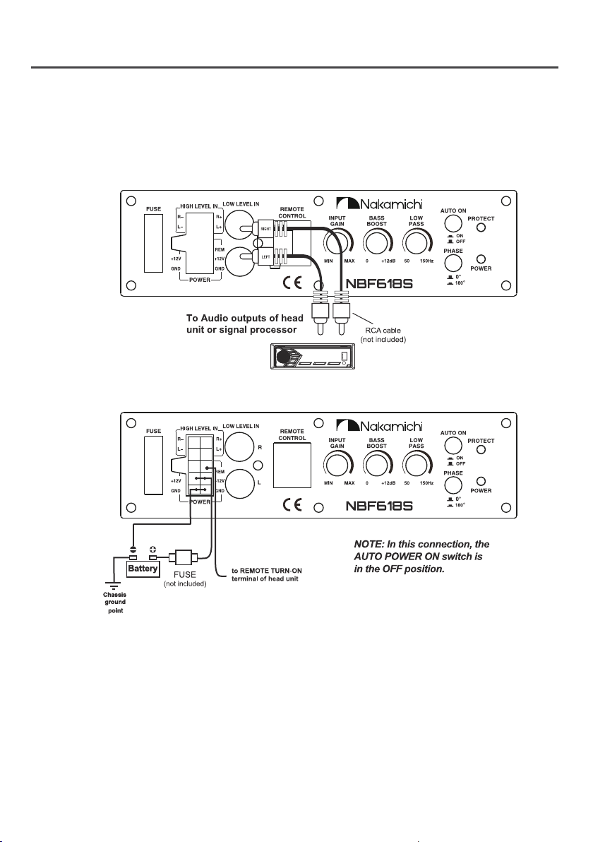
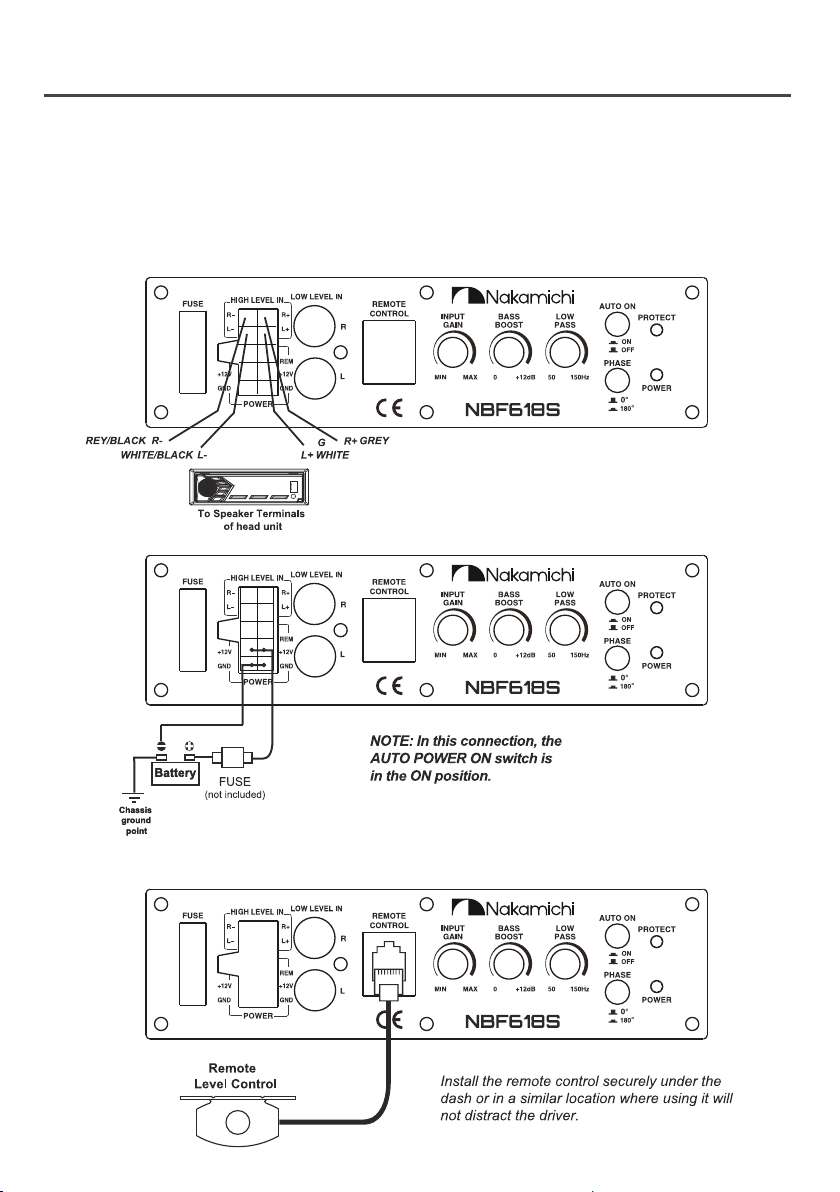
C. AUTO POWER ON
The AUTO POWER ON(ON/OFF) is for high level
(speaker-level) connections. When the switch
is in the "ON" position, the subwoofer will AUTO
POWER ON when there is signal input.If the
amplifier detected no signal input, the
amplifier will auto turn off, If you prefer to use
the remote turn on/off connection, the switch
is in the OFF position.
Note: Please connect the remote terminal to
the remote output of head unit as Fig.2 when
you hear the unit turn ON/OFF POP noise from
the subwoofer.
D. LOW PASS FILTER
This control permits you define the frequency
range you want the subwoofer amplifier to
receive. The subwoofer will reproduce all
sound below the frequency you set.
Note: The low pass filter frequency can be
higher or lower than the standard. There have
+/-20% tolerance.
E. BASS BOOST
The BASS BOOST feature will increase the
sound level in the bass frequencies.
F. INPUT GAIN CONTROL
After you have installed your system, turn this
control to minimum.
Turn the head unit on (and the subwoofer will
turn on via the remote connection). Turn the
head unit volume to about 2/3 full level.
Slowly turn up the subwoofer input gain
control until you hear a small amount of
distortion. Then reduce the level until the
distortion is completely gone. Level the
control at this setting.
G. LOW LEVEL RCA INPUTS
Low level inputs are the recommended way
to introduce the audio signal to the subwoof-
er if RCA outputs are present on your head
unit or other signal source (such as a sound
processor).
H. HIGH LEVEL (SPEAKER LEVEL) INPUTS
If your head unit does not have RCA outputs
you can use the speaker outputs for the audio
source for the subwoofer. Use the supplied
cable and wire harness and connect the
outputs properly as shown in the connection
diagram in this manual.
I. REMOTE LEVEL CONTROL PORT
Attach the included remote level control to
control the volume level of the subwooer
independently.
J. FUSE
Do not use a fuse with a different value and
never replace the fuse with a wire or coin.
K. POWER INPUT TERMINAL
L. PROTECT STAIUS LED
This LED glows red when protection circuits is
comes on.
PANEL CONTROLS AND FEATURES
3EN

WIRING
LOW LEVEL INPUT WIRING
Low-level (RCA) input wiring is preferred for best audio performance. Most trunk and under-seat
installations will require a 6-12 feet RCA cable. Always use a high quality cable.
POWER CONNECTIONS
Connect the ground terminal to the closest point on the chassis of the vehicle. Use 8 gauge (or
heavier) wire to connect the ground cable.
Connect the remote terminal to the remote output of head unit using 16 gauge ( or heavier )
wire.
Connect an empty fuse holder within 16" (40 cm) of the car battery, and run 8 gauge (or heavier)
cable from this fuse to the amplifier location. Then connect the fuse holder to the "BATT+" (+12V)
connection on the subwoofer rear panel.
NOTE: Do not connect both the high level and low level inputs from your receiver to your amplifier
at the same time!
Fig.1
Fig.2
4EN

WIRING
REMOTE LEVEL CONTROL CONNECTION
Fig.4
Fig.5
HIGH LEVEL INPUT WIRING
The high level input(s) should only be used when your receiver lacks RCA outputs. If the RCA
outputs are not present, connect the speaker outputs from the receiver to the high level input
connector of the amplifier. Be sure to observe polarity to avoid audio phase problems.
NOTE: Do not connect BOTH the high level and low level inputs from your receiver to your amplifier
at the same time!
Fig.3
5EN

TROUBLESHOOTING
If you experience operation or performance problems with this product, compare your installation
with the electrical wiring diagram on the previous pages. If problems persist,read the following
troubleshooting tips which may help eliminate the problems.
SYMPTOM
Products will not
power up
Check to make sure you have a good ground connection.
Check that the Remote Input (Turn-on) has at least 5V DC.
Check that there is battery power on the (+) terminal.
Check that there is at least 12V.
Check all fuse, replace if necessary.
Make sure that the Protection LED is not illuminated. If it is lit shut off the
amplifier briefly, and then repower it.
Protection LED comes
on when amplifier is
powered up
Turn down the volume control on the head unit to prevent overdriving.
Check that there is good air cirulation around the amp.
No output
Check that all fuses are OK.
Check that unit is properly grounded,
Check that the Remote Input (Turn-on) has at least 5V DC.
Check that the RCA audio cables are plugged into the proper inputs.
Low output Reset the Level Control.
Check the Crossover Control settings.
High hiss in the sound.
Disconnect all RCA inputs to the power sub's control panel. If the hiss
disappears, then plug in the component driving the amplifier and unplug
its inputs. If the hiss disappears at this point, go on until the faulty/noisy
component is found.
lt is best to set the amplifie's input level control as low as possible. The
best subjective signal-to-noise ratio is achieved in this manner. Try to set
the head unit as high as possible (without distortion).
Squealing noise is
present. Check for improperly grounded RCA interconnects.
Distorted sound. Check that the lnput Level Control is set to match the signal level of the
head unit.
POSSIBLE REMEDY
Engine noise
(static type)
This is usually caused by poor quality RCA cables, which can pick up
radiated noise. Use only the best quality cables, and route them away
from power cables.
Engine noise
(alternator whine)
Check that the RCA grounds are not shorted to the vehicle chassis.
Check that the head unit is properly grounded.
6EN

Made in China | 中國製造
WWW.NAKAMICHICARAUDIO.COM
INSTRUCTIONS & SOFTWARE DOWNLOADS AND WARRANTY REGISTRATION.
nakamichi.global
nakamichi.caraudio
CONNECT WITH US ONLINE TO EXPLORE NAKAMICHI’S COMPLETE RANGE,
Nakamichi Corp, Japan
Table of contents
Other Nakamichi Subwoofer manuals