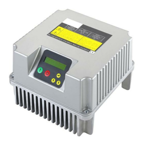
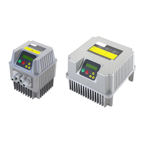
Nastec MIDA 203 Manual

MIDA
Installation, use and maintenance manual
V 6.0
24/04/2022
EN

Copyright © Nastec srl
The information contained in this document may be changed without notice
Nastec srl, Via della Tecnica, 8, 36048, Barbarano Mossano, Vicenza, Italy, Tel. +39 0444 886289, Fax +39 0444 776099, [email protected],
nastec.eu

Table of Contents
1. Introduction ........................................................................................................................................ 5
1.1. Purpose of the manual .............................................................................................................. 5
1.2. Product overview ...................................................................................................................... 5
2. Safety ................................................................................................................................................ 6
2.1. Symbols .................................................................................................................................. 6
2.2. Qualified personnel .................................................................................................................. 6
2.3. Safety warnings ....................................................................................................................... 6
2.4. Acoustic emission .................................................................................................................... 8
2.5. Certifications ............................................................................................................................ 8
3. Maintenance ....................................................................................................................................... 8
3.1. Maintenance ............................................................................................................................ 8
3.2. Warranty .................................................................................................................................. 9
3.3. Product registration .................................................................................................................. 9
3.4. Spare parts .............................................................................................................................. 9
3.5. Disassembly and repair .......................................................................................................... 10
3.6. Disposal ................................................................................................................................ 10
4. Transport and storage ....................................................................................................................... 10
4.1. Transport ............................................................................................................................... 10
4.2. Inspection on delivery ............................................................................................................. 10
4.3. Handling ................................................................................................................................ 11
4.4. Storage ................................................................................................................................. 11
5. Technical features ............................................................................................................................. 11
5.1. Name .................................................................................................................................... 11
5.2. Technical Data ....................................................................................................................... 11
5.3. Dimensions and weight ........................................................................................................... 13
5.4. Cables entry .......................................................................................................................... 13
6. Mechanical installation ...................................................................................................................... 13
6.1. Installation environment .......................................................................................................... 13
6.2. Cooling .................................................................................................................................. 14
6.3. Mechanical assembly of size 2 devices .................................................................................... 14
6.4. Assembly on-board the motor ................................................................................................. 16
6.5. Wall installation ...................................................................................................................... 18
7. Electrical installation .......................................................................................................................... 20
7.1. Grounding .............................................................................................................................. 20
7.2. Protection devices .................................................................................................................. 20
7.3. Connecting cables .................................................................................................................. 21
7.3.1. Power cables .............................................................................................................. 21
7.3.2. Control cables ............................................................................................................. 22
7.4. Electromagnetic Compatibility (EMC) ....................................................................................... 22
7.5. Electrical connections ............................................................................................................. 22
7.5.1. Power connections ...................................................................................................... 23
7.5.2. Control connections ..................................................................................................... 26
8. Commissioning ................................................................................................................................. 28
8.1. Preliminary checks ................................................................................................................. 28
8.2. Powering ............................................................................................................................... 28
9. Use and programming ....................................................................................................................... 29
9.1. Keyboard (version without display) .......................................................................................... 29
9.2. Keyboard and display ............................................................................................................. 30
9.3. Control via App ...................................................................................................................... 30
9.4. Initial display .......................................................................................................................... 31
9.5. FOC motor control .................................................................................................................. 31
9.5.1. Introduction ................................................................................................................. 31
9.5.2. FOC control calibration ................................................................................................ 31
9.5.3. Adjusting the FOC control ............................................................................................ 32
9.6. Menu ..................................................................................................................................... 33
9.7. Control parameters ................................................................................................................. 33
9.8. Motor parameters ................................................................................................................... 36
9.9. IN / OUT parameters .............................................................................................................. 37
MIDA
3

9.10. Connectivity parameters ....................................................................................................... 38
10. Constant pressure operation ............................................................................................................ 39
10.1. Introduction .......................................................................................................................... 39
10.2. The pressure vessel ............................................................................................................. 39
10.3. Electrical connections ........................................................................................................... 39
11. Splitting the pumping system ............................................................................................................ 40
11.1. Introduction. ......................................................................................................................... 40
11.2. Variable speed pumping unit with two or more pumps in COMBO mode. .................................. 40
11.2.1. Cascade operating principle. ...................................................................................... 40
11.2.2. Synchronous operating principle. ................................................................................ 41
11.2.3. Electrical connections. ................................................................................................ 41
11.2.4. Programming the master unit. ..................................................................................... 41
11.2.5. Programming of slave units. ....................................................................................... 42
11.2.6. Automatic master replacement ................................................................................... 42
12. Operation at constant differential pressure ........................................................................................ 42
12.1. Introduction .......................................................................................................................... 42
12.2. Electrical connections ........................................................................................................... 43
12.3. Programming ....................................................................................................................... 43
13. Alarms ............................................................................................................................................ 44
14. Alarms (version without display) ....................................................................................................... 47
15. Warnings ........................................................................................................................................ 50
16. Warnings (version without display) ................................................................................................... 51
17. EC Declaration of Conformity ........................................................................................................... 53
18. UK Declaration of Conformity ........................................................................................................... 54
MIDA
4

1. Introduction
1.1. Purpose of the manual
The purpose of this manual is to provide users with detailed information on the installation, operation, and mainte-
nance of the product, with special regard to safety regulations.
WARNING
Read the manual carefully before installing and using the product.
WARNING
Failure to follow the instructions may result in damage to the product, the system in which it is
installed and, in the worst cases, damage to property or persons with even fatal consequences.
NOTE
Store the manual in a protected and easily accessible place next to the installation location for
possible consultation. A digital copy of this manual can be downloaded from the manufacturer's
website or via the QR code shown on the product itself.
The complete installation, use and maintenance manual of the product, constantly updated in its contents, can be
downloaded by scanning the QR code shown in the product with the smartphone camera and following the relative
link.
1.2. Product overview
MIDAis a device for the control and protection of pumping systems based on the variation of the pump power
supply frequency. It can be applied to both new and old systems ensuring:
• energy and economic savings
• simplified installation and lower system costs
• extended life of the system
• improved reliability
MIDA, when connected to any pump on the market, it manages its operation in order to keep a certain physical
quantity constant (pressure, differential pressure, flow rate, temperature, etc.) as the conditions of use change.
In this manner, the pump, or the pump system, is operated only when, and to the extent that, it is needed, thus
avoiding unnecessary energy waste and extending its life. At the same time the device can:
• protect the motor from overloads and dry runs
• implement soft starts and soft stops to increase system life and reduce absorption peaks
• provide an indication of the current consumption and the supply voltage
• record the operating hours and, based on these, the errors and faults reported by the system
• connect to other devices to obtain combined operation
Appropriate output filters, available upon request, allow reducing the dangerous overvoltages that are generated in
very long cables and, therefore, make the device ideal also for controlling submerged pumps.
MIDA
5

2. Safety
2.1. Symbols
TIP
This symbol indicates a TIP or recommendation.
NOTE
This symbol indicates a NOTE or an indication or concept to be emphasised.
CAUTION
This symbol indicates CAUTION, thus an indication which failure to respect can lead to minor or
moderate damage.
WARNING
This symbol indicates a WARNING, thus an indication which, in the event of non-compliance, may
lead to serious, even fatal damage to persons or things.
DANGER
This symbol indicates an ELECTRICAL HAZARD, which if not avoided will result in death or electro-
cution.
2.2. Qualified personnel
WARNING
The installation, use and maintenance of the product are strictly for qualified personnel who have
undergone appropriate training. Any use by unqualified personnel must be carried out under the
approval, responsibility, and close monitoring of the latter.
WARNING
Failure to follow the instructions may result in damage to the product, the system in which it is
installed and, in the worst cases, damage to property or persons with even fatal consequences.
WARNING
Failure to comply with the instructions may lead to loss of warranty.
WARNING
Keep out of the reach of children.
2.3. Safety warnings
WARNING
During installation and use of the product, comply with the general safety regulations, working in a
clean, dry environment, free of hazardous substances and using the appropriate accident prevention
tools (gloves, helmet, goggles, shoes, and whatever else is necessary).
WARNING
The product is suitable for installation in industrial environments. In case of installation in a residential
environment, it is recommended to adopt all the safety precautions required by local regulations.
MIDA
6

WARNING
The unsuitable use of the product, non-original spare parts or tampering with the hardware and/or
firmware of the product may lead to serious damage to property or persons in addition to the loss of
warranty. The manufacturer waives all liability due to the improper use of its products.
WARNING
Before commissioning the product, ensure that the installation is safe and in accordance with local
regulations.
WARNING
Comply with the provisions to meet EMC requirements.
WARNING
Use cables of the appropriate type and cross-section according to the electrical characteristics of the
load, the ambient temperature and local regulations.
WARNING
Any insulation tests may only be performed in accordance with the manufacturer's instructions.
Failure to do so may result in damage to the unit.
CAUTION
Electronic boards and components may be damaged by electrostatic discharge. We therefore, rec-
ommend to don't touch the components.
CAUTION
Take care during installation and electrical connection that no foreign bodies enter into the device.
DANGER
During the entire period in which the device is powered, regardless of whether it is operated or
remains in stand-by (digital shutdown), high voltage is present inside the device and at the input and
output terminals.
DANGER
The device, previously in stand-by condition, may suddenly start up following the reset of an alarm
or changed system conditions. This may result in serious mechanical and electrical danger to the
operator who, upon seeing the device stopped, may have intervened on it, on the load or on the
system in which it is installed.
DANGER
Disconnect the device from the power supply, check that the load is completely stopped and wait at
least 15 minutes before intervening on it or on the load applied to it.
DANGER
If the motor is of the permanent magnet type, the device may be energized by the passive rotation of
the motor. In this case, both the power supply and the load should be disconnected before working
on the device itself.
DANGER
Ensure that the device is fully closed and all fixing screws are properly tightened before supplying
power. Do not remove the protective parts for any reason while the device is powered on.
DANGER
It is recommended to install the appropriate protection devices upstream of the device, such as a
circuit breakers, fuses and a residual current device (RCD).
MIDA
7

DANGER
Make sure that the device and the loads connected to it are properly grounded with the appropriate
connection terminals before commissioning.
Ensure that the grounding system is compliant and refer to local regulations for grounding devices.
Each load must be fitted with its own earthing cable, the length of which must be as short as
possible. Do not make interconnected grounding connections.
Leakage currents may exceed 3.5 mA. It is recommended to use the reinforced ground connection if
necessary.
CAUTION
During operation, some surfaces may reach high temperatures that may cause burns upon contact
with skin. Be very careful when touching the device!
Avoid contact with flammable products.
WARNING
Do not place any interrupting or switching devices between the inverter and the load. Interruption or
switching during motor operation may cause serious damage to the device.
WARNING
Do not perform insulation tests on the load or power cable without first disconnecting them from the
device.
2.4. Acoustic emission
The device has an acoustic emission:
<65 dB at a distance of 1 meter with cooling fans at maximum speed.
2.5. Certifications
The product has the following certifications:
• CE
3. Maintenance
3.1. Maintenance
WARNING
Before carrying out any work on the device, carefully read the chapter Safety [6] in the manual.
WARNING
Failure to follow the instructions may result in damage to the product, the system in which it is
installed and, in the worst cases, damage to property or persons with even fatal consequences.
WARNING
Failure to comply with the instructions may lead to loss of warranty.
The device requires the following maintenance:
Intervention Interval
Check that the unit is properly cooled, that the fans are functioning and that the cooling surfaces are
clean
Every 6 months, or following a tem-
perature alarm
Check for alarms Every 12 months
Check the correct tightening of the power terminals Every 12 months
Verify the maintenance of the protection rating (ingress of dust or water) by checking the tightening of the
screws in the mechanical closing parts, the gaskets, and the cable glands.
Every 12 months
MIDA
8

TIP
For more information contact the dealer or technical support at [email protected] or by opening a
support ticket on the portal service.nastec.eu
3.2. Warranty
Nastec guarantees that the products accompanied by this warranty are free from material or workmanship defects.
The Company has the right to inspect any product returned under warranty, and confirm that the product contains
a material or workmanship defect. The Company has the exclusive right to decide whether to repair or replace
defective equipment, parts or components. To qualify for the warranty coverage, the buyer must return the product
to the place of purchase. Subject to the terms and conditions listed below, the Company agrees to repair or
replace any part of this product that has material or workmanship defects. The Company will evaluate products
under warranty for 24 months from the date of installation (only in case of product registration) but no longer than
36 months from the date of invoice. IN NO EVENT shall the Company be liable for any other costs incurred by
the customer in removing and/or fastening any product, part or component thereof. The Company reserves the
right to change or improve its products or any part thereof, without being obliged to provide such a change or
improvement for products previously sold. THIS WARRANTY DOES NOT APPLY to products damaged by natural
events, including lightning, normal wear and tear, normal maintenance services, or any other condition beyond the
control of the Company. THIS WARRANTY WILL BE VOIDED if any of the following conditions occurs:
• The product is used for purposes other than those for which it was designed and manufactured.
• The product has not been installed in accordance with applicable codes and rulings.
• The product has not been installed by qualified personnel.
• The item has been damaged due to negligence, abuse, misapplication, tampering, alteration, improper installa-
tion, operation, maintenance and storage.
If the customer wishes to make a warranty claim, it is necessary:
• Fill in the warranty claim on the service.nastec.eu portal
• Wait for the result from the Nastec technical support service. The outcome may envisage the following:
• Absence of warranty based on the information received. A quotation for repair or spare parts may be made
upon request.
• Warranty advanced based on information received. Nastec will decide if the product is to be replaced under
warranty. However, Nastec reserves the right to inspect the product.
• Need to receive the product by the manufacturer in order to establish the potential warranty. Following the
analysis of the returned product, Nastec will establish the unquestionable existence or absence of the warranty
conditions by providing a detailed report on the damage found and its origins. If the warranty is applicable,
Nastec will repair the device. Nastec is willing to refurbish the product upon offer. In the absence of a warranty,
Nastec will make an offer to repair and/or refurbish the device. After 60 days from the offer, if no response
is received from the buyer, Nastec will scrap the product upon notice. Nastec does not cover any warranties
provided by the buyer to third parties, without its prior authorization.
3.3. Product registration
By registering the product on the portal service.nastec.eu, it is possible to activate the manufacturer's warranty
valid for 24 months from the registration date up to a maximum of 36 months from the date of manufacture,
according to the warranty conditions. Registration must be completed within one month from the date of installation
of the product.
The warranty is offered through the distribution chain. It is therefore necessary to specify the official distributor
or importer from which the product was purchased. Alternatively, the distributor can register the product in the
customer's name.
3.4. Spare parts
The manufacturer provides spare parts for the device. Contact your dealer for more information.
WARNING
It is recommended to use only original spare parts.
WARNING
Failure to follow the instructions may result in damage to the product, the system in which it is
installed and, in the worst cases, damage to property or persons with even fatal consequences.
MIDA
9

WARNING
Failure to comply with the instructions may lead to loss of warranty.
3.5. Disassembly and repair
If it is necessary to disassemble and repair the device, it is recommended that the safety instructions be strictly
observed.
WARNING
The installation, use and maintenance of the product are strictly for qualified personnel who have
undergone appropriate training. Any use by unqualified personnel must be carried out under the
approval, responsibility, and close monitoring of the latter.
WARNING
Failure to follow the instructions may result in damage to the product, the system in which it is
installed and, in the worst cases, damage to property or persons with even fatal consequences.
WARNING
Failure to comply with the instructions may lead to loss of warranty.
TIP
For more information contact the dealer or technical support at [email protected] or by opening a
support ticket on the portal service.nastec.eu
3.6. Disposal
Devices marked with this symbol cannot be disposed of in household waste but must be disposed of at appropriate
waste drop-off centres. It is recommended to contact the Waste Electrical and Electronic Equipment drop-off
centres (WEEE) in the area. If not disposed of properly, the product may have potential harmful effects on the
environment and on human health due to certain substances present within. Illegal or incorrect disposal of the
product is subject to severe administrative and/or criminal penalties.
4. Transport and storage
4.1. Transport
Avoid subjecting the product to severe shocks or extreme weather conditions during transport. The packaging must
remain dry and at a temperature between -20°C (-4°F) and +70°C (+158°F). Do not stack packages without first
checking feasibility with the manufacturer.
TIP
It is advisable to always indicate FRAGILE on the packaging
4.2. Inspection on delivery
Upon receipt of the product, check:
• the integrity of the packaging
• the integrity of the content
• the presence of all components
In case of problems, notify the forwarder immediately.
MIDA
10

WARNING
The manufacturer declines all responsibility for damage to the product due to transport
4.3. Handling
The product must be handled by hand or using suitable lifting equipment in relation to its weight and the regulations
in force.
If necessary, use dedicated handling equipment (cranes, ropes, trolleys), using the lifting points provided in the
product.
During handling it is recommended to:
• Handle with care
• keep away from suspended loads
• always wear accident prevention equipment
• be careful not to damage electrical cables
Do not handle the product using electrical cables as lifting gear.
WARNING
Failure to follow the instructions may result in damage to the product, the system in which it is
installed and, in the worst cases, damage to property or persons with even fatal consequences.
4.4. Storage
The product must be stored in its packaging in a dry place, without sudden changes in humidity and temperature
and protected from mechanical (weights, vibrations), thermal and chemical agents.
The temperature of the storage environment must be between -20°C (-4°F) and 70°C (+158°F) with a maximum
relative humidity of 85% (non-condensing).
If the product remains in stock for more than 24 months from the manufacturing date shown on the packaging, it is
necessary to check the mechanical integrity of its parts and supply power to it at least once every 12 months.
If the product is put back into storage after it has been used, it is advisable to contact the manufacturer for further
information on storage.
TIP
For more information contact the dealer or technical support at [email protected] or by opening a
support ticket on the portal service.nastec.eu
5. Technical features
5.1. Name
MIDA ABCD - EFGH
•MIDA:Product name
•A: Nominal AC supply voltage (2 =1x230 VAC, 3 = 3x230 VAC, 4 = 3x400 VAC)
•BCD Rated output current
•EF: Customization code (01 = standard customization)
•G: Mounting kit included in the package (0 = none, 1 = motor, 2 = wall, 3 = motor+wall)
•H: Pressure sensor included in the package (0 = none, 1 = pressure sensor 0-16 bar)
5.2. Technical Data
Electrical specifications by model:
Model Vin +/- 15% [VAC] Max V out [VAC] Max I in
[A]
Max I out
[A]
Typical
motor P2
[kW]
Maximum
efficiency [%]
Size
MIDA 203 1 x 230 3 x Vin 4,5 3 0,55 94,5 1
MIDA 205 1 x 230 3 x Vin 7,5 5 1,1 94 1
MIDA
11

Model Vin +/- 15% [VAC] Max V out [VAC] Max I in
[A]
Max I out
[A]
Typical
motor P2
[kW]
Maximum
efficiency [%]
Size
MIDA 207 1 x 230 3 x Vin 11 7,5 1,5 94 1
MIDA 304 3 x 230 3 x Vin 3,7 4 0,75 96 1
MIDA 306 3 x 230 3 x Vin 5,4 6 1,1 96 1
MIDA 309 3 x 230 3 x Vin 8 9 2,2 96 1
MIDA 314 3 x 230 3 x Vin 13,5 14 3 97 2
MIDA 318 3 x 230 3 x Vin 17,5 18 4 97 2
MIDA 325 3 x 230 3 x Vin 24 25 5,5 97 2
MIDA 330 3 x 230 3 x Vin 29 30 7,5 97 2
MIDA 338 3 x 230 3 x Vin 42 38 9,2 97 2
MIDA 344 3 x 230 3 x Vin 52 48 11 97 2
MIDA 404 3 x 380 - 460 3 x Vin 3,7 4 1,1 96 1
MIDA 406 3 x 380 - 460 3 x Vin 5,4 6 2,2 96 1
MIDA 409 3 x 380 - 460 3 x Vin 8 9 4 96 1
MIDA 414 3 x 380 - 460 3 x Vin 13,5 14 5,5 97 2
MIDA 418 3 x 380 - 460 3 x Vin 17,5 18 7,5 97 2
MIDA 425 3 x 380 - 460 3 x Vin 24 25 11 97 2
MIDA 430 3 x 380 - 460 3 x Vin 29 30 15 97 2
MIDA 438 3 x 380 - 460 3 x Vin 36 38 18,5 97 2
MIDA 444 3 x 380 - 460 3 x Vin 42 44 22 97 2
General electrical specifications:
Power supply frequency 50 - 60 Hz (+/- 2%)
Voltage unbalance between the power supply phases +/- 2%
Maximum output frequency 300 Hz
EMC compliance EN61800-3 C1 for single-phase models, C2 for three-phase models
Energy efficiency class (according to EN61800-9-2) IE2
Environmental specifications:
Relative humidity of the operating environment 5 - 95 % non-condensing
Workplace temperature from -10 °C (14 °F) to 60 °C (140 °F)
Maximum workplace temperature at nominal load 40°C (104 °F)
Power derating beyond maximum temperature -2.5% every °C (-1.4% every °F)
Maximum altitude at nominal load 1000 m (3280 ft)
Power derating beyond maximum altitude - 1% every 100 m (328 ft)
Mechanical specifications:
Protection rating IP66 (NEMA 4X)
Resistance to vibrations EN60068-2-6:2008, EN60068-2-27:2009, EN60068-2-64:2008,
WARNING
Protect the device from direct exposure to weather and sunlight.
MIDA
12

5.3. Dimensions and weight
39
248
337 mm
97 mm33
211 mm
150 27
76 114 mm
Size Maximum weight [kg]
1 2,5
2 10
5.4. Cables entry
Cable gland Tightening torque
[Nm]
Cable diameter
[mm]
Size
1
Size
2
Size
2
MIDA 338 , MIDA 344 ,MIDA 438 , MIDA 444
M12 1,5 3,5-7 3 6 6
M16 3 5-10 - 2 2
M20 6 7-13 2 - -
M25 8 10-17 - 2 -
M40 13 19 -28 - - 2
6. Mechanical installation
WARNING
Read the safety chapter carefully before continuing.
6.1. Installation environment
WARNING
The environmental specifications stated in the technical data of the product must be strictly complied
with.
WARNING
Do not install the device in environments at a risk of explosion, flooding, or in the presence of
flammable fluids or solids. Ensure sufficient ventilation in the room.
Refer to local regulations when selecting the appropriate installation location.
MIDA
13

WARNING
The degree of protection of the device is only ensured if, at the end of the installation, the cover
screws and the cable glands have been properly tightened. Close the holes of unused cable glands
with the appropriate plugs.
Protect the device from direct exposure to weather and sunlight.
Do not leave the device installed without cover or with the cable glands open, even if not connected
to the power supply. The infiltration of dust, water or humidity may irreparably damage the device.
WARNING
To ensure uninterrupted operation, the device can gradually and automatically reduce performance
before shutting down following over-temperature. However, prolonged operation above the rated
temperature leads to a reduction in the life of the device.
6.2. Cooling
The device is cooled primarily by forced air circulation through the heat sink element.
In addition to the heat sink, the device also uses the remaining surfaces to cool itself. It is therefore necessary to
ensure sufficient space around the device during installation.
In particular, the distance between the suction and discharge side of the heat sink and the other surfaces must be
at least:
• 150 mm for current intensity up to 18 A
• 200 mm for current intensity up to 30 A
• 250 mm for current intensity up to 44 A
On the other sides, maintain a minimum distance of 100 mm to ensure cooling and to make installation and
maintenance operations easier.
During operation, the surfaces of the device can become hot enough to cause burns. Do not touch them.
In the case of installation inside electric cabinet, it is necessary to guarantee the appropriate air flow for the heat
dissipation of all the components. The heat released by the device may be calculated from its conversion efficiency.
WARNING
Do not place any heat-generating elements (outlet filters) on the suction side of the device to prevent
dangerous overheating.
6.3. Mechanical assembly of size 2 devices
The size 2 devices are equipped with a quick connection system that allows carrying out both power and signal
electrical connections on the fixed part, called "base", while the mobile part, called "power", is applied later.
This allows working smoothly during electrical connections without running the risk of damaging the power part. It
also facilitates quick power replacement in case of failure without the need to remove connections.
To open the device, please follow the instructions shown in the figure and proceed with caution.
MIDA
14

In size 2 devices, the ground connection between the base and the power is made by means of four metal pins on
the power side that engage into four special holes on the base with spring contacts. At the same time, these metal
pins serve as a guide for a correct coupling between the base and the heat sink.
MIDA
15

DANGER
Be careful not to damage or remove the four metal pins, as this will not only compromise the
mechanical coupling between the base and the power, but also the ground connection.
6.4. Assembly on-board the motor
The device may be installed in place of the motor terminal box cover both horizontally and vertically. It is necessary
to check with the motor manufacturer whether the base of the device can be fastened to the motor casing.
The seal on the base of the device provides protection against the ingress of water and dust. Drill the seal only
in the area where the four holes for fastening to the motor casing are. It is possible to use the same screws
and washers with which the terminal box cover was fastened to the motor casing. Please refer to the following
instructions when fastening the device to the motor.
DANGER
At the end of the installation, check the ground continuity between the base of the device and the
motor casing.
MIDA
16

On-board motor installation for size 1 devices
63
63
73
73
5.5
65
65
60
4.5
U
V
W
P.E.
12
34
MIDA
17

On-board motor installation for size 2 devices
71
(max 100)
71
(max 100)
100
100
65
65
5.5
132
132
75
116
12
34
6.5. Wall installation
Wall installation is carried out by means of the special metal bracket available on request.
MIDA
18

Wall installation for size 1 devices
Wall installation for size 2 devices
DANGER
The ground continuity between the base of the device and the bracket is ensured by the special
component shown in the figure. Install this component and verify the ground continuity between the
bracket and the base of the device at the end of the installation.
Alternatively, it is possible to drill the aluminum base in the area where the four special fixing holes are.
The fixing screws must be equipped with O-rings to guarantee the protection rating.
MIDA
19

7. Electrical installation
WARNING
Read the safety chapter carefully before continuing.
7.1. Grounding
DANGER
Make sure that the device and the loads connected to it are properly grounded with the appropriate
connection terminals before commissioning.
Ensure that the grounding system is compliant and refer to local regulations for grounding devices.
Each load must be fitted with its own earthing cable, the length of which must be as short as
possible. Do not make interconnected grounding connections.
Leakage currents may exceed 3.5 mA. It is recommended to use the reinforced ground connection if
necessary.
Use the following minimum cross-sections for ground cables:
• cross-section equal to the mains power cable cross-section up 16 mm2. (6 AWG)
• 16 mm2 (6 AWG) for mains power cable cross-section between 16 mm2 (6 AWG) and 35 mm2 (1 AWG).
• cross-section equal to half the cross-section of the power supply cable when the latter is greater than 35 mm2 (1
AWG).
7.2. Protection devices
DANGER
It is recommended to install the appropriate protection devices upstream of the device, such as a
circuit breakers, fuses and a residual current device (RCD).
Fuses and switches.
The control device can protect the motor from overloads by digitally controlling the absorbed current against the set
rated current.
It is therefore not necessary to install any overload protection device between the inverter and the motor.
Instead, it is necessary to install overcurrent and short-circuit protection devices, such as fuses and circuit break-
ers, upstream of the device. These trigger in the event of failure of a component inside the device.
Supply voltage Model Recommended fuse
gC
Recommended circuit breaker
ABB MCB S200
1 x 230 VAC MIDA 203 10 S201-C10
1 x 230 VAC MIDA 205 10 S201-C10
1 x 230 VAC MIDA 207 16 S201-C16
3 x 230 VAC MIDA 304 10 S203-C10
3 x 230 VAC MIDA 306 10 S203-C10
3 x 230 VAC MIDA 309 16 S203-C16
3 x 230 VAC MIDA 314 20 S203-C20
3 x 230 VAC MIDA 318 25 S203-C25
3 x 230 VAC MIDA 325 30 S203-C32
3 x 230 VAC MIDA 330 35 S203-C40
3 x 230 VAC MIDA 338 50 S203-C50
3 x 230 VAC MIDA 344 63 S203-C63
3 x 380 - 460 VAC MIDA 404 10 S203-C10
3 x 380 - 460 VAC MIDA 406 10 S203-C10
3 x 380 - 460 VAC MIDA 409 16 S203-C16
3 x 380 - 460 VAC MIDA 414 20 S203-C20
3 x 380 - 460 VAC MIDA 418 25 S203-C25
MIDA
20
Other manuals for MIDA 203
1
This manual suits for next models
20
Table of contents
Other Nastec Controllers manuals