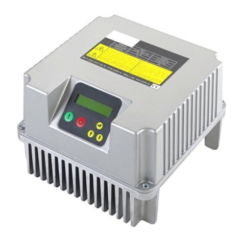
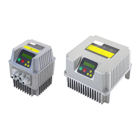
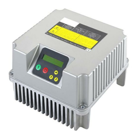
Nastec HMA Series User manual

Operating manual
HMA
manHMA_eng_00

2
Index
1. Introduction to HMA ......................................................................................................................................................... 3
2. Safety Instructions............................................................................................................................................................. 4
3. Technical Characteristics ................................................................................................................................................... 5
3.1 Weight and dimensions .......................................................................................................................................................... 5
4. Electric wiring.................................................................................................................................................................... 6
4.1 Protections............................................................................................................................................................................... 8
4.2 Electromagnetic compliance.................................................................................................................................................... 8
5. HMA installation............................................................................................................................................................ 9
6. HMA Use and Programming .............................................................................................................................................10
6.1 HMA display .......................................................................................................................................................................... 10
6.2 Initial configuration ............................................................................................................................................................... 10
6.3 Initial view ............................................................................................................................................................................. 11
6.4 Menu view............................................................................................................................................................................. 12
6.5 Control parameters ............................................................................................................................................................... 12
6.6 IN/OUT parameters................................................................................................................................................................ 13
6.7 Connectivity parameters........................................................................................................................................................ 14
7. Protections and alarms.....................................................................................................................................................15

3
1. Introduction to HMA
HMA is an electronic device for switching between power sources that integrates multiple functions:
Automatic power source management: HMA, combined with any MultiPower “HMA ready” device, switches
between AC power (mains or generator) and DC power (photovoltaic panels) completely automatically, based on the
programmed logic.
Mechanical disconnection of the two power supplies: Two interlocked contactors guarantee the uniqueness of the
power supply and ensure separation in order to ensure maximum electrical safety.
Control of auxiliary generator: When the AC power is provided by a generator, HMA is able to start or stop it
according to need. HMA also monitors any signs of failure or running out of fuel.
Five programmable switching logics can meet any application requirement.

4
2. Safety Instructions
The manufacturer strongly suggests carefully reading this operation manual before using and installing its products
Any operation (installation, maintenance and repair) must be carried out by trained, skilled, and qualified personnel.
Failure to observe and follow the instructions in this manual may result in dangerous and potentially lethal electric shock.
Pay attention to all standard safety and accident prevention regulations
The device must be connected to both power supply (DC: photovoltaic panels
and AC: grid or generator) via a switch to ensure the complete disconnection
from the supply before any operation on the HMA and on the connected load.
Do not remove, for any reason, the cover and the cable plate without having first
disconnected the device from the power supply and having waited at least 5
minutes.
The system must be grounded properly before operation.
Install safety devices on both DC and AC side.
Avoid any shock or significant impact during transport.
Check the product immediately upon delivery and check for damage and/or missing parts. If either occurs, immediately
notify the supplier.
Damages due to transport, incorrect installation, or improper use of the device will null and void the warranty.
Tampering or disassembly of any component will automatically void the warranty.
The manufacturer cannot be held responsible for any damages to people and/or property due to improper use of its
products.
Devices marked with this symbol cannot be disposed of in household waste but
must be disposed of at appropriate waste drop-off centres. It is recommended
to contact the Waste Electrical and Electronic Equipment drop-off centres
(WEEE) in the area. If not disposed of properly, the product can have potential
harmful effects on the environment and on human health due to certain
substances present within. Illegal or incorrect disposal of the product is subject
to serious administrative and/or criminal penalties.

5
3. Technical Characteristics
Model
VDC
VAC
I max
Compatibility
HMA 218
90-400
1 x 9 0 - 2 6 5
18 A
4HS MP
SUND
MIDA Solar 203-207 MP
VS 218 MP
HMA 430
190-850
3 x 1 9 0 - 520
30 A
VS 212 MP
VS 409-430 MP
HMA 485
190-850
3 x 1 9 0 - 520
85 A
VS 438-485 MP
Ambient temperature at rated current: da -10 a 50°C
Max altitude at rated current: 1000 m.
Grade of protection: IP54 (NEMA 12)*
Connettivity: MODBUS RTU RS485, Bluetooth® SMART (4.0)
* avoid direct exposition to solar rays.
3.1 Weight and dimensions
Model
Weight *
Size
[Kg]
HMA 218
XX.X
3
HMA 430
XX.X
3
HMA 485
XX.X
3
* Weight without packaging.

6
4. Electric wiring
HMA 218
AC input
P.E., T1, T2
DC input
+, -, P.E.
It is necessary to respect the
polarity.
AC/DC output
F1+, F2-, P.E.
It is necessary to respect the
polarity.
HMA 430
AC input
P.E., T1, T2, T3
DC input
+, -, P.E.
It is necessary to respect the
polarity.
AC/DC output
F1+, F2-, F3, P.E.
It is necessary to respect the
polarity.
HMA 485
AC input
P.E., T1, T2, T3
DC input
+, -, P.E.
It is necessary to
respect the polarity.
AC output
F1, F2, F3, P.E.
DC output
+, -, P.E.
It is necessary to
respect the polarity.
It is recommended to use cable lugs.

7
Control board
Analog inputs (10 or 15 Vdc):
1. AN1: 4-20 mA
2. AN2: 4-20 mA
3. AN3: 4-20 mA / 0 - 10 Vdc (settable
by jumper C.C.)
4. AN4: 4-20 mA / 0 - 10 Vdc (settable
by C.C.)
Digital outputs:
Power source signal relay:
NO1, COM1: closed contact with AC power supply
NC1, COM1: closed contact with DC power supply
Alarm Relay:
NO2, COM2: contact closed without alarm.
NC2, COM2: contact closed with alarm or without
power supply.
Generator start / stop relay:
NO3, COM3: contact closed for generator start.
NC3, COM3: contact open for generator start.
The digital output relays are non-voltage contacts.
The maximum voltage applicable to the contacts is
250 V AC, max 5 A.
RS485 for COMBO with
device to be controlled:
S1+
S1-
G
It is recommended to
respect the polarity
linking devices.
Digital inputs:
IN1 : float or pressure switch for
pump start and stop
IN2: AC / DC switch
IN3: genset alarm
IN4 : genset lack of fuel
0V
We recommend using only no voltage
contacts.
5V power supply (max 1 A):
• 0V
• + 5V
RS485 for MODBUS:
S2+
S2-
G
It is recommended to
respect the polarity.

8
Communication with HMA Ready device
The communication between the HMA and the HMA ready device that is intended to be powered is made via serial port
RS485 COMBO.
It is enough to use a three wire cable with a minimum section of 0.5 mm2 connected to the terminals S1 +, S1-,G.
4.1 Protections
The protections required upstream HMA depend on the type of installation, and local regulations.
Safety protections on both AC and DC side must be used.
For DC side we recommend to use 1000 VDC circuit breaker and, if possible, 1000 VDC surge protection.
For AC side we recommend to use overload protection with the characteristic curve of type C and type B circuit breaker,
sensitive to both AC and DC current.
4.2 Electromagnetic compliance
To ensure electromagnetic compatibility (EMC) of the system, it is necessary to apply the following measures:
Always connect the device to ground
Use shielded signal cables by placing the screen at one end.
Use motor cable as short as possible (<1 m / <3 ft). For longer lengths, it is recommended to use shielded cables
connecting the screen at both ends.
Separate signal, motor, and power supply cables.

9
5. HMA installation
HMA can be installed on the wall following the holes shown in the drawing.
The IP54 protection degree (NEMA 12) allows installation even in humid and dusty environments. However, it is
recommended to avoid direct exposure to atmospheric agents and sunlight.

10
6. HMA Use and Programming
HMA software is extremely simple to use, but allows a wide variety of parameters to be set for ideal system calibration.
Setting Parameters is protected by password:
1: Installer level (MENU’ CONTROL PARAMETERS, MENU’ IN/OUT PARAMETERS, MENU’ CONNECTIVITY PARAM.)
A password is required for this level; these parameters are adjustable by trained professionals
Default password: 001
From the menu a different password can be set up.
Installer level can be entered only with the correct password; otherwise, it is impossible to set up and/or modify any
parameters (they can be only displayed).
6.1 HMA display
It is a backlit display with 2 rows of 16 characters.
An acoustic signal accompanies the user in use and provides a quick indication in case of an alarm.
6.2 Initial configuration
When HMA is switched on for the first time, the initial setting menu is displayed for the initial setting of parameters to
configure the system. If the initial setting procedure is not completed properly, it is impossible to run the system. Initial
setting procedure can be repeated if necessary.
A brief description of parameters and their allowable ranges are listed below:
Parameter
Default
Description
XXXXX
End user communication language
Language
XXXXX
Switch to DC
/ Menù exit
Switch to AC
/ Menù exit
ENTER
Scroll up
Scroll down
AC + DC to
interrupt power
supply

11
XXXXX
Time setting.
ON
Bluetooth communication enabling.
Once the Setting procedure is completed you will get this indication on the
display; setting parameters are recorded. These parameters can be set up
individually in the menu.
6.3 Initial view
In provides an indication of the power supply available at the HMA input (DC, AC or
DC + AC).
Inv provides information on the status of the device connected to the HMA.
During the transition phases from one power source to the other, the Inv indication
flashes.
The VDC and VAC voltage is also displayed.
Display of current time.
In switch mode time or flow with AC start time, the exchange time from one power
source to the other is also indicated.
Status display:
INV SUPPLY:OFF: both power sources are disabled (by simultaneously pressing
the AC and DC buttons).
INV SUPPLY: DC: DC power supply.
INV SUPPLY: AC: AC power supply.
DC Wait: waiting for the DC supply to stabilize for 5 minutes before attempting
to switch to DC.
AC Wait: waiting for the AC supply to stabilize before attempting to switch to AC.
Low PV Energy: Not enough energy to follow the switching in DC.
In case of alarm the corresponding alarm is indicated.
By pressing the ENTER key it is possible to access the diagnostic menù which shows:
Total hours of AC or DC power supply of the HMA.
AC power hours.
DC power hours.
History of the last 8 alarms referred to Total Hours.
The daily flow rate which is automatically reset every day at dawn is indicated in flow
exchange mode.
Pressing the ENTER key again exits the diagnostic menu.
Pressing the ENTER key accesses the menu.
Current Time
XX h : XX m
BTLE Connection
ON/OFF
INITIAL SETUP
COMPLETED
In: AC/DC Inv: ON/OFF
XXX [V]
In: AC/DC Inv: ON/OFF
XX : XX
ALL. XXXXXXXXXXXXX
XXXXX h : XX m
DC hours
XXXXX h : XX m
AC hours
XXXXX h : XX m
Total hours
XXXXX h : XX m
In: AC/DC Inv: ON/OFF
XXXXXXXXX
STATO
Menù
ENT to access

12
6.4 Menu view
Pressing the ENTER key in correspondence with [MENU ’/ ENT to access] in the initial display accesses the menù. To exit the
menu display and return to the initial display, press one of AC or DC buttons.
Installer password required to enter level 1 (default 001)
6.5 Control parameters
Parameter
Default
Description
Manual
Auto
Flow
Time
Ext. Input
MPPT
It is possible to choose between:
• Manual: using the keyboard it is possible to switch from one
power supply to another or even interrupt the power supply.
• Auto: if the radiation falls below a certain value or the power
generated by the panels is not sufficient to operate the pump,
the HMA starts the generator, if present, and exchanges with AC
power. When the irradiation returns above the minimum
threshold, the generator is switched off and the pump is
restarted with DC power. In the absence of a solarimeter, the
HMA exchanges to AC if the DC supply is no longer sufficient to
guarantee pump operation at minimum frequency.
• Flow: the exchange from DC to AC power supply is made
automatically to satisfy the desired daily flow rate. It is also
possible to set a time after which to allow the transition to AC.
• Time: the transition from the photovoltaic power source to the
mains supply (or generator) and vice versa occurs at a time set
by the user.
• Ext. Input: The exchange is controlled by the opening or closing
of digital input 2.
XXXXX
Time setting.
MENU’
Control. param.
MENU’
IN/OUT. param.
MENU’
Connect. param.
MENU’
Change init.set.
Switch Mode:
Manual
Auto
Flow
Time
Ext. Input
Current Time
XX h : XX m

13
Parameter
Default
Description
Manual
Auto
Flow
Time
Ext. Input
0
Irradiation value for the exchange
from AC to DC supply.
05
Without a solarimeter installed, the
HMA will attempt to restart in DC
based on this parameter, doubling the
time for each restart attempt up to a
maximum of 60 minutes.
XX
It is the daily flow value to be satisfied
with a possible transition from DC to
AC supply.
Auto
In Switch Mode: Flow, the Auto AC
Starting Mode provides for immediate
transition to AC as soon as the DC is
not sufficient. In Timed AC Starting
Mode the exchange takes place at a
set time.
XX
Set time for the passage from DC to
AC.
XX
Set time for the passage from AC to
DC.
By pressing the ENT key it is possible
to change the installer level password
(level 1) (default 001).
6.6 IN/OUT parameters
Parameter
Default
Description
N.O.
Digital input 1 is used to parallelize the signal coming from a float or
pressure switch connected to the digital input 1 of the HMA ready
device powered by HMA.
N.O. (Normally Open) or N.C. (Normally Closed) must be the same on
both devices.
The polarity in the connection must be respected.
N.O.
Digital input 2 is used to exchange the two power sources when the
selected Switch Mode is Ext. Input
DC Start Thresh.
XXXX [W/m2]
DC Start Delay
XX [min]
Daily Flow
V = XXX.X [m3]
AC Starting Mode
Auto/Timed
AC Starting Time
XX h : XX m
DC Starting Time
XX h : XX m
Change PASSWORD
ENT
Digital input 1
N.O. / N.C.
Digital input 2
N.O. / N.C.

14
Parameter
Default
Description
N.O.
Digital input 3 can be connected to the alarm signal of the generator.
N.O.
Digital input 4 can be connected to the signal of lack of fuel of the
generator.
1
Digital input 1 and 2 delay.
The digital input has a fixed delay of 1 sec.
By pressing the ENT key it is possible to change the installer level
password (level 1) (default 001).
6.7 Connectivity parameters
Parameters
Default
Description
XXXXX
End user communication language
1
MODBUS address from 1 to 247
9600
MODBUS baudrate from 1200 bps to 57600 bps
RTU N81
MODBUS data format: RTU N81, RTU N82, RTU E81, ETU O81
ON
Bluetooth communication enabling.
By pressing the ENT key it is possible to change the installer level password
(level 1) (default 001).
Digital input 3
N.O. / N.C.
Digital input 4
N.O. / N.C.
Dig.In.1/2 delay
[s]
Change PASSWORD
ENT
Language
XXXXX
MODBUS address
XXX
MODBUS baudrate
XXXXX [bps]
MODBUS data format
XXXXX
BTLE Connection
ON/OFF
Change PASSWORD
ENT

15
7. Protections and alarms
Anytime a protection occurs a blinking message is displayed together with an audible alarm; on STATUS in the initial view, the
protection is displayed; by pressing AC or DC button, only from this position (STATUS) in the initial view, is it possible to try to
reset the alarm; if HMA does not reset the alarm it is displayed again together with an audible sound.
Alarm message
Alarm description
Possible solutions
LOW BATTERY
The internal battery voltage is lower
than the minimum allowed
threshold.
Keep the HMA powered by one of the two power
sources for at least two hours and if the alarm
persists, contact the technical service.
5V OVER CURRENT
5V power supply overload (greater
than 1 A).
Remove the load connected to the 5V supply and
check the causes of excessive absorption.
OVER TEMP. PCB
Overtemperature of the electronic
board.
Check that the ambient temperature is below the
maximum allowed.
OVER VOLTAGE
Overvoltage in DC power supply.
Check the causes of overvoltage.
AC CLOSING FAULT
Failure to detect closure of the AC
contactor.
Check the wiring of contactor.
Check the function of the contactor.
DC CLOSING FAULT
Failure to detect closing of the DC
contactor.
Check the wiring of contactor.
Check the function of the contactor.
AC OPEN. FAULT
Failure to detect opening of AC
contactor.
Check the wiring of contactor.
Check the function of the contactor.
DC OPEN. FAULT
Failure to detect opening of DC
contactor.
Check the wiring of contactor.
Check the function of the contactor.
GENERATOR FAULT
Opening or closing of digital input 3
detected.
Check the correct configuration of the digital input 3.
Check the wiring to the digital input 3.
Check the generator.
GEN. FUEL. LACK
Opening or closing of the digital
input 4 detected.
Check the correct configuration of the digital input 4.
Check the wiring to the digital input 4.
Check the fuel level in the generator.
NO COMM.INVERTER
Lack of communication between the
HMA and the device powered by it.
Check if the device is powered.
Check the COMBO serial wiring.
Check the device power supply wiring.

16
KEYBOARD FAULT
A keyboard button has been
pressed for more than 120 seconds
Check that the push-button panel is not accidentally
pressed
Call the assistance service
GENERAT. TIMEOUT
Failure to detect AC power within
30 seconds of starting the
generator.
Check the generator start signal wiring.
Check the AC power supply wiring.
Check the correct functioning of the generator.
INV SUPPLY:OFF
Deactivation of both AC and DC
contactors following the
simultaneous pressing of both the
AC and DC buttons.
Select a power source using the corresponding
button.
INV SUPPLY: DC
Closing the DC contactor
INV SUPPLY: AC
Closing the AC contactor
AC Wait
Waiting for the AC power supply
(generator) following a request.
DC Wait
Waiting for the DC supply to
stabilize for 5 minutes before
attempting to switch to DC.
Charging Battery
Battery charging in progress.
Low PV Energy
Insufficient energy to switch to DC.
Daily Flow OK
Daily flow rate reached.

17
NOTE

18

19
This manual suits for next models
3
Table of contents
Other Nastec Controllers manuals
Popular Controllers manuals by other brands

InDeM automation
InDeM automation VIVO 424 Installation and user manual

Siemens
Siemens OpenAir GQD Series installation instructions

SBC
SBC Saia PG5 Mounting instructions

Shinko
Shinko DCL-33A instruction manual

DITEC
DITEC EL16 Installation handbook

Honeywell
Honeywell EXCEL 5000 OPEN ZAPP installation instructions