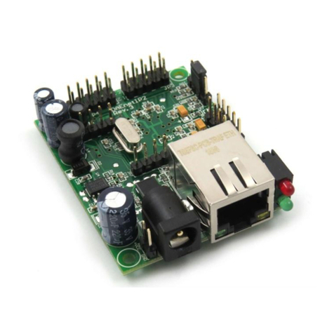
Denkovi DAEnetIP4 User manual

DAEnetIP4 User Manual
08 June 2018
-1-
DAEnetIP4
Web enabled IP Controller
User Manual
Date: 08 June 2018

DAEnetIP4 User Manual
08 June 2018
-2-
Content
1. Features....................................................................................................................... 3
2. Application examples.................................................................................................... 4
3. Technical parameters..................................................................................................11
4. Connectors and ports (interfaces) ...............................................................................12
4.1. DAEnetIP4 ports ................................................................................................12
4.2. DAEnetIP4 ports, led-s and jacks description.....................................................12
5. Installation...................................................................................................................15
5.1. Connect..............................................................................................................15
5.2. Power supply requirements................................................................................15
5.3. Network connection............................................................................................17
5.4. Communication setup.........................................................................................18
6. Reset and default settings...........................................................................................21
6.1. Table with default settings..................................................................................21
6.2. Steps for loading default settings .......................................................................23
6.3. Restart the module.............................................................................................23
7. Web access.................................................................................................................24
7.1. Login..................................................................................................................25
7.2. Menu..................................................................................................................26
7.3. General Settings ................................................................................................27
7.4. Network settings.................................................................................................28
7.5. Date and Time Settings......................................................................................29
7.6. HTTP, XML and JSON Access...........................................................................30
7.7. SNMP Agent......................................................................................................32
7.8. SNMP Traps ......................................................................................................33
7.9. Digital Inputs......................................................................................................34
7.10. Analog Inputs.....................................................................................................35
7.11. Digital Outputs....................................................................................................36
7.12. PWM Outputs.....................................................................................................39
7.13. Monitoring and control........................................................................................40
7.14. Week Schedule..................................................................................................41
7.15. Logout................................................................................................................42
7.16. Reboot...............................................................................................................42
8. HTTP/XML/JSON access............................................................................................43
8.1. Login (Encrypted Password) ..............................................................................43
8.2. Login (Non-Encrypted Password).......................................................................44
8.3. Getting the I/O current state...............................................................................45
8.4. Multiple XML/JSON Access................................................................................47
8.5. Parameters ........................................................................................................47
9. SNMP access..............................................................................................................48
9.1. Product ..............................................................................................................48
9.2. Traps..................................................................................................................48
9.3. Setup .................................................................................................................48
9.4. Week Schedule..................................................................................................51
9.5. Control...............................................................................................................52
10. Security considerations...........................................................................................53
11. I/O Ports.................................................................................................................54
11.1. Digital Outputs Ports JP1/JP3............................................................................54
11.2. Digital Inputs Port JP2........................................................................................55
11.3. Analog Inputs Port JP4.......................................................................................56
11.4. PWM Port JP6....................................................................................................57
12. PCB mechanical drawing........................................................................................58

DAEnetIP4 User Manual
08 June 2018
-3-
1. Features
DAEnetIP4 is the next generation multifunctional Ethernet device (IP controller) for
management and control. It could be used for industrial and home automation,
access control, fire and security systems and embedding in other systems. It is
suitable also for controlling relay boards, monitoring different analogue sensors via
internet.
DAEnetIP4 features include:
10/100 Mb Ethernet interface;
Auto-MDIX;
Extended supply voltage range (7.5V - 25V) DC
Low power consumption - 40mA at 24V DC;
16 (2x8) Digital Outputs;
8 Analog Inputs (10 bit resolution);
8 Digital Inputs (16 bit counters);
2 PWM outputs (10 bit resolution);
Real Time Clock (RTC) for schedule (calendar) stand-alone work;
Extra status led;
Web server with secure login authorization;
SNMPv1 for configuration/monitoring (get,set,bulk,table,getnext,walk);
Secure HTTP/XML/JSON API protocol support for read/write Inputs/Outputs;
Supported protocols: ARP, IP, HTTP, ICMP (ping), DHCP, DNS;
Access protection (by IP and MAC address);
Option for saving Digital Outputs states and restoring on reset;
Scaling (linearization) for the analog inputs to show values in suitable units;
Single Input may be forwarded to control many Digital Outputs;
Sending traps according to Analog Input level and Digital Inputs state;
Working temperature range: 0ºC to 70ºC.

DAEnetIP4 User Manual
08 June 2018
-4-
2. Application examples
Bellow are shown ideas how DAEnetIP4 could be used. The examples are only
conceptual and an additional equipment is required in actual implementations:
Electrical appliances remote control applications
Figure 1. Controlling electrical appliances remotely
DAEnetIP4 can be used to control electrical appliances with combination of
mechanical relays, solid state relays, contactors and so on. It has 16 Digital Outputs
so it can control 16 electrical devices independently. Supports various integration
protocols (SNMP, HTTP/XML, Web-browser access) so these devices can be
accessed via any modern device from all over the world.

DAEnetIP4 User Manual
08 June 2018
-5-
Monitoring and logging applications
Figure 2. Monitoring sensors
DAEnetIP4 can be used with success into monitoring and logging systems. It has
8 x 10 bit Analog Inputs (10-bit resolution) which can be level-extended in order to
monitor temperature, humidity, distance, light and so on.

DAEnetIP4 User Manual
08 June 2018
-6-
Standalone applications with sensors and electrical devices
Figure 3. Controlling electrical devices depending on sensors values
The controller supports mode in which the Analog/Digital Inputs (sensors) can
control the Digital Outputs (electrical devices).

DAEnetIP4 User Manual
08 June 2018
-7-
Counters in shops
Figure 4. DAEnetIP4 used in application for counting customers in shops
DAEnetIP4 provides 8 x 16 bit counters (from 0 up to 65535) which can be
used to count various events - for example detect when a person enters in a
shop through the door. DAEnetIP4 increment its counter and saves this in its
RAM memory. With suitable software and database it could be easily
organized a monitoring and statistic system without concerns that even an
event will be missed.

DAEnetIP4 User Manual
08 June 2018
-8-
Web based thermo-regulator
Figure 5. Web based thermo-regulator
Every DAEnetIP4 Digital Output can be set to work in "Regulator" mode where it
can be controlled just from an Analog Input. The controller can be adjusted to set
different outputs upon the input level from single Analog Input (one input can be
configured to control many outputs). For example, one output can be set for heating,
another for cooling and etc. All the process may be monitored online and this makes
DAEnetIP4 suitable for standalone Web enabled thermo-regulator.

DAEnetIP4 User Manual
08 June 2018
-9-
Home automation
Figure 6. DAEnetIP4 can be used in home automation systems
DAEnetIP4 can be used for home automation applications as well.
oIt has 2 x PWM (Pulse Width Modulation) outputs which can be used (with
extension board) for lights dimming;
oThanks to it's week schedule feature (it has built in RTC), it could turn
on/off appliances up to 30 times per day;
oSetting with pulse. Every Digital Output can be configured to generate a
single pulse (from 0 up to 65553 seconds) which could be suitable for
controlling garage doors, windows, roofs and for any other application
where a certain period of time should be maintained;
oDAEnetIP4 supports mode of controlling the Digital Output from Digital
Input (buttons, switches...), Analog Input (sensors for temperature,
humidity, distance, light...), RTC (week schedule), Manual Control
(browser, SNMP, HTTP/XML) at the same time. This means the output
could be controlled for example from smart-phone, wall switch and light
sensor at the same time and with priority is the last action.
oUsing the "Regulator" mode for the Digital Outputs can ensure for example
opening and closing the door blinds based on the level of the outside
sunlight;

DAEnetIP4 User Manual
08 June 2018
-10-
Irrigation systems
Figure 7. DAEnetIP4 can be used in home irrigation systems
One of the possible applications for DAEnetIP2 is to be integrated in irrigation
systems. It features two different modes:
oStart and stop irrigation based on particular time. As DAEnetIP4 has its
own RTC (real time clock) and build in back-up power (for days) it can turn
on and off the system up to 30 times per a single day - it has organized a
week schedule based table inside. The clock can be synchronized via
internet from NTP server during a given period of a time.
oStart and stop irrigation based on humidity level. DAEnetIP4 can also set
the solenoid valves upon the level from humidity or rain sensor which
ensures that if it is rainy it won't start the system. This is because the
Analog Inputs of the controller can control the Digital Outputs
independently without computer (standalone mode).

DAEnetIP4 User Manual
08 June 2018
-11-
3. Technical parameters Table 1. Technical parameters
Parameter
Value
Size (L / W / H), mm
85 / 48 / 17
Power supply voltage, V DC
7.5 - 25
Current consumption, mA
40mA at 24V, 70mA at 12V, 90mA at 9V
Digital outputs count
16 (2 x 8)
Digital outputs voltage, V
0 or 3.3
Analog Inputs count
8
Analog Inputs reference voltage, V
2.048
Analog Inputs resolution, bits
10
Digital Inputs count
8
Digital Inputs voltage range, V
0 up to 5.5
Counters count*
8
Counters resolution, bits
16
PWM outputs count
2
PWM frequency, KHz
40
PWM output voltage, V
0 up to 3.3
PWM resolution, bits
10
Default settings jumper
Yes
Reset jumper
Yes
Save I/O states and load on boot
Yes
DHCP
Yes
DNS
Yes
Hardware Real Time Clock (RTC)
Yes
Network parameters
IP/Mask/Default gateway
MAC lock (protection)
Yes
SNMPv1
Yes (set,get,table,walk,getnext,bulk)
Read-Write Community String
Yes
Read-Only Community String
Yes
SNMP traps
Yes
Secure HTTP/XML access
Yes
SNMP I/O access commands
Yes
Web server for configuration/access
Yes
* Combined with Digital Inputs

DAEnetIP4 User Manual
08 June 2018
-12-
4. Connectors and ports (interfaces)
4.1. DAEnetIP4 ports
Bellow is shown a picture with the device connectors, ports and led indicators.
Figure 8. Device overview
4.2. DAEnetIP4 ports, led-s and jacks description
The first pin of every I/O port is marked with square footprint and all the rest pins
are with circle footprints. Table 2. Digital Outputs port JP1
Pin N
Bit
Function
Direction
1
0
General Purpose Output #1
OUT
2
1
General Purpose Output #2
OUT
3
2
General Purpose Output #3
OUT
4
3
General Purpose Output #4
OUT
5
4
General Purpose Output #5
OUT
6
5
General Purpose Output #6
OUT
7
6
General Purpose Output #7
OUT
8
7
General Purpose Output #8
OUT
9
-
GND
-
10
-
3V3
-

DAEnetIP4 User Manual
08 June 2018
-13-
Table 3. Digital Inputs port JP2
Pin N
Bit
Function
Direction
1
0
General Purpose Input #1
IN
2
1
General Purpose Input #2
IN
3
2
General Purpose Input #3
IN
4
3
General Purpose Input #4
IN
5
4
General Purpose Input #5
IN
6
5
General Purpose Input #6
IN
7
6
General Purpose Input #6
IN
8
7
General Purpose Input #7
IN
9
-
GND
-
10
-
3V3
-
Table 4. Digital Outputs port JP3
Pin N
Bit
Function
Direction
1
8
General Purpose Output #9
OUT
2
9
General Purpose Output #10
OUT
3
10
General Purpose Output #11
OUT
4
11
General Purpose Output #12
OUT
5
12
General Purpose Output #13
OUT
6
-
+VCC
-
7
-
+VCC
-
8
-
GND
-
9
-
GND
-
10
-
GND
-
11
13
General Purpose Output #14
OUT
12
14
General Purpose Output #15
OUT
13
15
General Purpose Output #16
OUT
Table 5. Analog Inputs port JP4
Pin N
Bit
Function
Direction
1
-
ADC Channel #1
AIN
2
-
ADC Channel #2
AIN
3
-
ADC Channel #3
AIN
4
-
ADC Channel #4
AIN
5
-
ADC Channel #5
AIN
6
-
ADC Channel #6
AIN
7
-
ADC Channel #7
AIN
8
-
ADC Channel #8
AIN
9
-
GND
-
10
-
Vref (+2.048V)
-
Table 6. System port JP5
Pin N
Bit
Function
Direction
1
-
Default (factory) settings
IN
2
-
GND
-
3
-
GND
-
4
-
Reset
IN

DAEnetIP4 User Manual
08 June 2018
-14-
Table 7. PWM port JP6
Pin N
Bit
Function
Direction
1
-
PWM1
OUT
2
-
PWM2
OUT
3
-
GND
-
Figure 9. Power and status led
The top led next to the RJ-45 indicates power presence (usually red). The bottom
led is an indicator for status (usually green).
Figure 10. Power jack polarity
The inner pin of the power supply jack is the positive (+VCC) and the outer is the
negative (GND).

DAEnetIP4 User Manual
08 June 2018
-15-
5. Installation
5.1. Connect
This device must be installed by qualified personnel;
This device must not be installed directly outdoors;
Installation consists of mounting the device, connecting to an IP network,
connecting the I/O, providing power and configuring via a web browser.
5.2. Power supply requirements
Figure 11. Location of DAEnetIP4 power jack
DAEnetIP4 has the following current consumption:
40mA at 24V DC
70mA at 12V DC
90mA at 9V DC
It is recommended the supply source for DAEnetIP4 to be with the following
parameters:
Supply voltage: 7.5V - 25V DC;
Current: minimum 100mA;
It must be stabilized and filtered;
Type: center positive (the inner pin of the power supply adaptor jack must be
+VCC).
+VCC
GND
(NEGATIVE)
Figure 12. How the power supply cable must looks like

DAEnetIP4 User Manual
08 June 2018
-16-
Additionally, you can check if the supply adaptor has this sign:
+-
Figure 13. The power supply must be marked with this sign
DAEnetIP4 has protection against reverse polarity which is actually diode
in parallel of the supply jack but it is still not recommended to reverse the
voltage polarity!
DAEnetIP4 does not accept AC supply voltage. It is highly recommended
to check the power supply source parameters before turning on the
module.
The power supply equipment shall be resistant to short circuit and
overload in secondary circuit.
When in use, do not place the equipment so that it is difficult to disconnect
the device from the power supply.

DAEnetIP4 User Manual
08 June 2018
-17-
5.3. Network connection
DAEnetIP4 supports AUTO-MDIX so either "crossover" or "straight-through"
network cable can be used.
Figure 14.UTP Cable
Figure 15.Connecting DAEnetIP4 to a computer directly (recommended initial
connection)
Figure 16.Connecting DAEnetIP4 to a wireless router.

DAEnetIP4 User Manual
08 June 2018
-18-
5.4. Communication setup
DAEnetIP4 is shipped with the following default parameters:
IP address: 192.168.1.100
Subnet mask: 255.255.255.0
Gateway: 192.168.1.1
Web password: admin
Initially it is recommended to connect the module directly to the computer.
Next you have to change your PC’s IP address.
You can Google how to change you computer IP settings or just visit this
web page: http://www.howtochangeipaddress.com/changeip.php
For Windows 7 OS for example you can do that in the following way:
Navigate to Control Panel -> Network and Internet -> View network and status
tasks -> Change adapter settings
Then just select the local area connection with right click and select Properties:
Figure 17.LAN card properties

DAEnetIP4 User Manual
08 June 2018
-19-
The next step is to enter into IPv4 properties.
Figure 18.Enter in IPv4 properties section
Set the IP address of your PC to be in the same network.
Figure 19. Set the IP address

DAEnetIP4 User Manual
08 June 2018
-20-
Finally, in order to access DAEnetIP4 just type in your browser 192.168.1.100
Figure 20.Open the device via browser
If the network settings are O’K, the log-in page should appear:
Figure 21.Login page
DAEnetIP4 modules connected locally can be easily scanned and found
via the tool Denkovi Finder as well.
Figure 22.Denkovi Finder
Other manuals for DAEnetIP4
2
Table of contents
Other Denkovi Controllers manuals
Popular Controllers manuals by other brands
Mitsubishi
Mitsubishi Alpha XL quick start guide

Swagelok
Swagelok RHPS Series user manual
ETC
ETC QuickTouch Preset user guide

JLCooper Electronics
JLCooper Electronics SloMoPro user manual
Honeywell
Honeywell Spyder BACnet PUB1012S installation instructions

Omega Engineering
Omega Engineering HE-XE103 user guide
