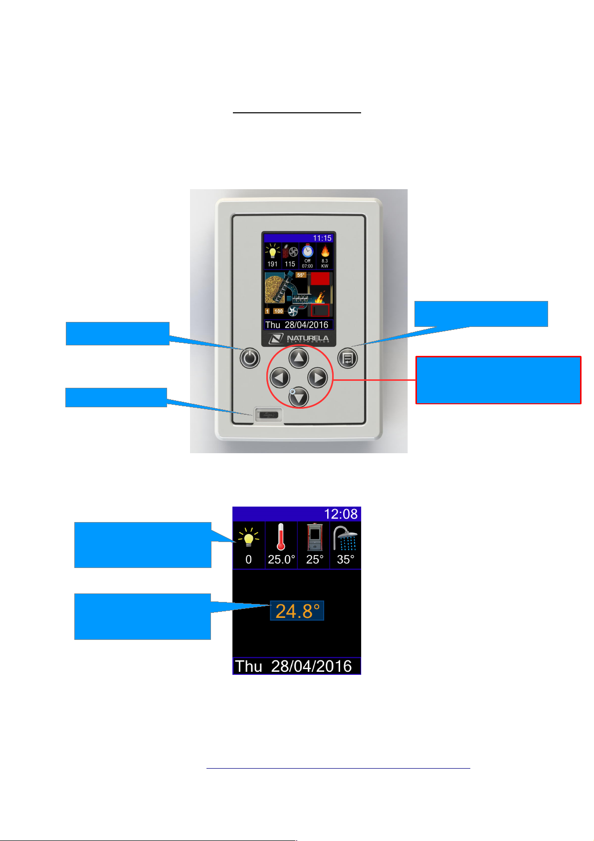
NRC-6-SV Room Thermostat and Remote Control Module
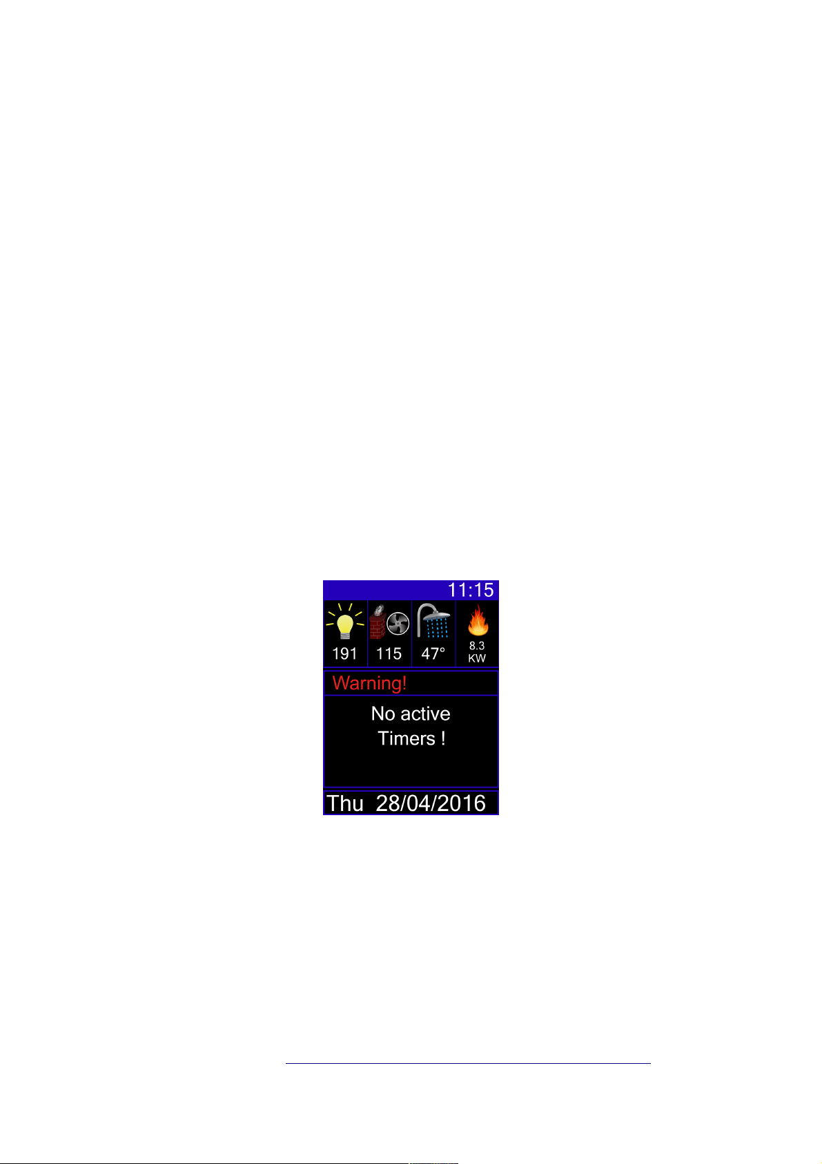
When the burner s turned ON:
When the burner is switched on and detects the light from a burning fire, a flame will appear in the
picture of a kettle/boiler. If multiple messages need to be displayed on the bottom row, the
messages will circulate between one another every four seconds. The date is displayed in white
color, operation stage is in green, and registered errors are in red.
If the clock was not previously set, the display will show –:-- . In order for the burner to work properly,
the time needs to be set
In most cases, when error messages are displayed in red on the bottom row, you will be
notified by a three tone sound signal.
Some of the error messages are automatically cleared from the screen after the cause for the error
has been resolved. There are other alarm notifications such as back burning”, frozen boiler,” etc.,
which can only be cleared from the screen if the “◄“ button is pressed down for over two seconds.
User Manual Ver 3.3 http://www.naturela-bg.com/en p.4 /21
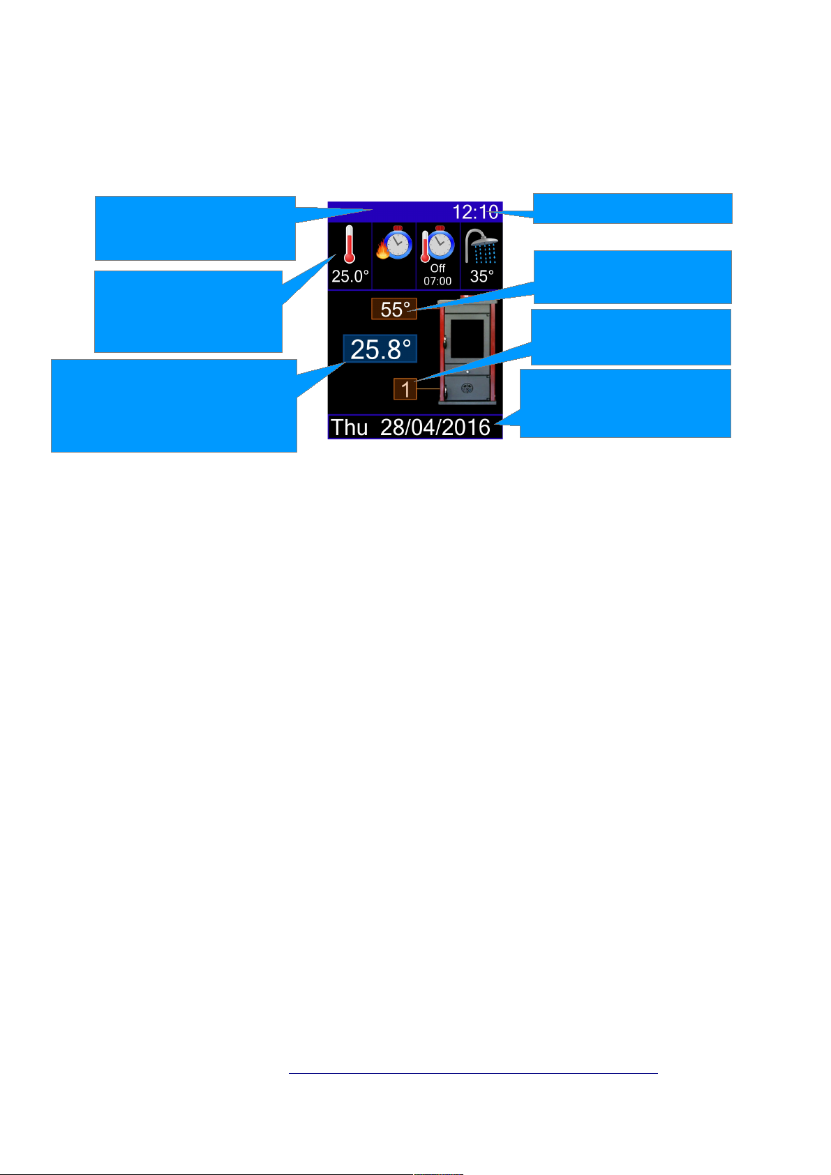
Time
Temperature of the water
in the boiler
Date,
burner's work phase (table 1)
or registered error (table 2)
Status bar with icons for the
outputs' current state and
Internet connection
Information fields with an
option to choose between
the displayed parameters
Information fields with an
option to choose between
the displayed parameters
Information fields with an
option to choose between
the displayed parameters
A measured ambient temperature.
The digits are in white, when the
set temperature is reached and in
orange, when it is not reached
Fuel type and number
currently in use