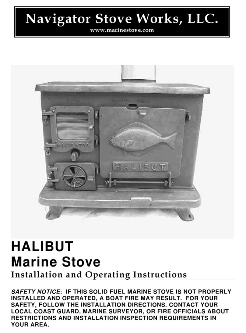
Navigator NSW1. User manual

Model # NSW1. Marine Stove
Installation and Operating Instructions
SAFETY NOTICE: IF THIS SOLID FUEL MARINE STOVE IS NOT
PROPERLY INSTALLED AND OPERATED, A BOAT OR HOUSE
FIRE MAY RESULT. FOR YOUR SAFETY, FOLLOW THE
INSTALLATION DIRECTIONS. CONTACT YOUR LOCAL COAST
GUARD, MARINE SURVEYOR, BUILDING OR FIRE OFFICIALS
ABOUT RESTRICTIONS AND INSTALLATION INSPECTION
REQUIREMENTS IN YOUR AREA.
Navigator Stove Works, LLC.
www.marinestove.com

2
UTABLE OF CONTENTSU
GENERAL INFORMATION
UMARINE INSTALLATION
U1. POSSIBLE HAZARDS TO AVOID WHEN USING THE U#NSW1.UON BOARD
2. INSTALLATION & SAFETY NOTICE
3. OPERATION
4. MAINTENANCE
URESIDENTIAL INSTALLATION
U5. POSSIBLE HAZARDS TO AVOID WHEN USING THE U#NSW1.UAT HOME
6. INSTALLATION & SAFETY NOTICE
7. OPERATION
8. MAINTENANCE
U
WARNING
U
DO NOT LEAVE THIS STOVE
UNATTENDED WHILE IN OPERATION
SAFE EFFICIENT OPERATION OF THIS
MARINESTOVE IS THE PRODUCT
OF TWO FACTORS:
UA CAREFULLY TENDED FIRE AND
PROPER INSTALLATION

3
UGeneral InformationU
This owner’s manual describes the installation and operation of Navigator’s
Model # NSW1. Marine Stove for wood. This marine stove may be installed
within a boat or a land-based residence. As a result, there are two sets of
instructions which detail the proper installation and operation for each
application. Please follow the instructions which apply to you. Do not
interchange installation requirements.
Codes and Regulations compiled from the following sources serve as the basis
for the instructions contained in this document:
ABYC “A-7” *1
NFPA “302” *2
NFPA “211” *3
40 CFR 60 - AAA *4
CAN/CSA B365-M91 *5
(See Appendix for Details)
Navigator’s Model #NSW1. Marine Stove has met the U.S. EPA’s emission
standards for residential wood heaters sold after May 15, 2015 (crib wood
standard).
Not approved for sale after May 15, 2020
It has also passed Washington State emission standard # WAC 150-31-200.
This stove has a particulate emission rating of 3.5 G/Hr. @ 86% Efficiency.
This efficiency rating was determined as a result of testing based on EPA Test
Method 28 / Sec.5.1 & Sec.5H / Cat.2 and CSA B415.1
Btu Rating of 11,400 – 19,400.
This wood heater needs periodic inspection and repair for proper
operation. It is against federal regulations to operate this wood heater in
a manner inconsistent with operating instructions in this manual.
This wood heater has a manufacturer-set minimum low burn rate that
must not be altered. It is against federal regulations to alter this setting
or otherwise operate this wood heater in a manner inconsistent with
operating instructions in this manual.
When installing, operating, and maintaining your #NSW1, follow the guidelines
given in these instructions. Save these instructions and make them available to
anyone using the stove.
A number of areas in the USA & Canada require a building permit to install
a solid-fuel burning appliance. NFPA 211 (National Fire Prevention
Association, Standard for chimneys, fireplaces, vents and solid-fuel

4
burning appliances) or CAN/CSA B-365 (Installation code for solid-fuel
burning appliances & equip.) may apply to the installation of solid-
fuel burning appliances in your area. Your stove dealer has knowledge of
your local codes and can provide assistance in making sure your
installation is safe and legal. Also contact your insurance representative,
building inspector, marine surveyor, US & CDN Coast Guard, or local fire
officials to determine what regulations apply in your area.
UMARINE INSTALLATION
U
1. Possible Hazards to Avoid
Any use of fire in a boat represents a certain danger. With intense over firing,
temperatures on the surface of the #NSW1. can exceed 1000°F. (536°C).
Comply with the following guidelines:
•Never install a #NSW1. in a boat that is powered by a gasoline engine.
•Never over fire the stove. If any part of the stove or chimney glows, you are
over firing, and a boat fire or serious damage to the stove or chimney could
result. Immediately close down the air controls if you notice this condition.
•Teach children that the stove is hot and must not be touched.
•Never use gasoline, or gasoline-type lantern fuel, kerosene, diesel, charcoal
lighter fluid or similar liquids to start or “freshen up” a fire in the stove. They
can ignite with explosive force, causing bodily injury or death. Keep all such
liquids far away from the stove while it is in use.
•Never use the stove if there are combustible vapours in the boat. The vapours
from certain cleaning fluids, adhesives, and polyurethane paints are a few
examples of combustible vapours. Remember that operating a solid-fuel fired
marine stove is a source of “open flame”.
•Keep combustible materials far away from the stove.
•A vent system or other means shall be provided to allow the discharge from
the boat of hydrogen gas released by the battery. Battery boxes with a cover
that forms a pocket over the battery shall be vented.
•Do not locate traditional marine oil lamps directly over the stove. Oil spillage
onto a hot stove will cause a fire.
•Do not dry clothes over the stove, since they could fall and ignite.
•Fabrics located above and within 39” of the stove used for decorative or other
purposes shall be flame resistant in accordance with NFPA 701, Standard
methods of fire tests for flame-resistant textiles & films.
•To prevent injury, do not allow anyone to use this stove who is unfamiliar with
the correct operation of the stove.

5
•Avoid creating a “Low Pressure” condition in the space where the stove is
operating, such as by operating an exhaust fan. A low pressure condition could
cause poisonous gasses to be drawn out of the stove and into the room. Carbon
monoxide (CO) is toxic, so please follow the guidelines in this manual to avoid
smoke “roll out” from the burn chamber. You can prevent a low pressure
condition by providing adequate outside combustion air within 24 inches of the
stove. Keep a port, hatch, or window open while operating the stove!
Install a smoke/carbon monoxide monitoring device in the space the stove
is installed and in any and all adjacent cabins. Maintain the device as
directed by the manufacturer.
•If for some reason smoke “rolls out” of the stove, it might activate a smoke
alarm or carbon monoxide detector.
•To avoid smoke or flame spillage, open the air adjuster and the stove pipe
damper before opening the door to fill the stove with fuel.
•Never operate the stove if it is damaged, missing parts, or has been modified
in any way.
•Always use protective gloves when adding fuel to the fire.
•Do not operate the stove during severe storm conditions at sea. Stow cook
surface cover plates, air adjuster and handles.
*Please note: The attached CO data submitted in the stove certification
application and the expected variations for different operation conditions from
Min.Low Output to Max.High Output.
2. Installation
SAFETY NOTICE: IF THIS SOLID FUEL MARINE STOVE IS NOT
PROPERLY INSTALLED AND OPERATED, A BOAT FIRE MAY
RESULT. FOR YOUR SAFETY, FOLLOW THE INSTALLATION
DIRECTIONS. CONTACT YOUR LOCAL COAST GUARD,
MARINE SURVEYOR OR FIRE OFFICIALS ABOUT
RESTRICTIONS AND INSTALLATION INSPECTION
REQUIREMENTS IN YOUR AREA.
Please read this entire manual before you install and use your new stove.
Failure to follow instructions may result in property damage, bodily injury, or
even death.
We recommend that you have your #NSW1. Installed by a
professional installer of solid-fuel marine stoves.
Remove Stove From Crate

6
When removing the stove, UDo not lift the stove by it’s stainless steel “sea
rail.” UThis part is only designed for keeping cook pots in place while at sea. Lift
the stove free from the crate by grasping the outer-most edges of the cast iron
top.
Carefully remove the cover plate, and cover plate handle from inside the foam
packing.
Use a soft cloth or mat and “tip” the stove onto one of it’s sides (an old piece of
carpet works well to protect the porcelain). Watch the door as you do this!
Before you carefully right the stove, check to see that the four thru-bolt wing
nuts are just “hand tight”.
Under no circumstances should you tighten these fasteners with a wrench
or pliers. This could cause one of the castings to fracture when the stove
heats up.
Place the circular cover plate in its place on the cook surface.
Planning the Installation....
If you are considering installing a #NSW1. in a vessel which has had a
previously installed stove hearth and/or chimney pipe, it is critical that you have
the existing components inspected for safety.
Safe stove installation involves several aspects: (A) the chimney pipe / deck
iron combination. (B) protecting combustible materials in the vicinity of the
stove. (C) securing the stove. Each of these aspects is equally important for a
safe and secure installation. Consult with a Marine Surveyor. If your craft is
insured, please also check with your agent regarding installing a marine stove.
Efficient use of this stove will be assured by installing it in a location where its
heat output will contribute the greatest impact to the space(s) requiring heat.
A. Chimney Pipe
The chimney pipe should be of 4” Dia. stainless steel with a minimum thickness
of 26 gauge. Secure sections of pipe together with three sheet metal screws per
joint to insure that the sections will not separate.
Generally, chimney pipe sections must be attached to each other with the
crimped end Utoward the stoveU. This allows any small amount of condensed
creosote to run down toward the hot stove rather than onto the outside of
the pipe. The pipe connection at the oval flange on the stove top should
however go OVER the oval collar.
Single-wall smoke pipe and stacks shall have a minimum clearance of 9
inches (23 cm.) from combustible materials including painted materials or
shall be separated by fire resistant thermal insulation that is acceptable to the
authority having jurisdiction. NFPA Standards #302 / 211

7
Consult with a Marine Surveyor to determine the protection system best suited
for your installation if you cannot maintain the minimum 9” clearance. This
system will commonly consist of a layered panel, made from 20 Ga. sheet
stainless and 5/8” mineral board, spaced 1” from the combustible surface to
which it is attached.
*Exception: at decks equipped with a water iron. (NFPA 302, 6 - 3.3)
UWater Deck Iron
UEither a bronze or a cast iron “water deck iron” shall be used. This traditional
fitting contains water in a trough which surrounds and cools the chimney pipe as
it passes through the deck. Follow manufacturer’s installation & operation
instructions when installing this hardware. Keep the trough filled with water
while operating the stove.
Permanent installations shall make use of double or triple wall stainless pipe or
shall have a safety grille attached to the outside of single wall pipe which will
eliminate accidental direct contact with hot piping. Double or triple-wall stove
pipe meeting the requirements of UL 103, Standard for Safety Factory-Built
Chimneys for Residential Type and Building Heating Appliances, shall be
installed in accordance with the specifications of the manufacturer.
A flue damper shall be installed in the pipe roughly 30” above the cook surface
of the stove. The damper is a critical component which will enable the user to
control the stove’s draft. Do not install a #NSW1. without a damper.
UFlue Pipe Draft DamperU
Do not use aluminum or galvanized pipe as chimney pipe. These materials
cannot withstand the operating temperatures of a fire and can give off toxic
fumes when heated. Round stove pipe must be hand formed to an oval shape
which will then slide onto the stove’s oval flue collar.
The connection between the 4” chimney pipe and the stove’s oval flue
collar should be sealed (from inside) with stove cement after the pipe is
installed. Design the piping so that no more than a total of two 90 degree
bends are utilized. Horizontal runs shall rise at 1/4 inch per foot.
Chimney piping may not be run through a closet, locker or other concealed
space. Always connect this stove to a chimney and vent to the outside of the
vessel. Install a Smoke Head which is designed to minimize water entry, spark
emission and back draft. In very bad weather do not operate the stove. Safely

8
stow the smoke head and install a plug which will effectively seal the deck
iron‘s opening in the event of the vessel overturning.
USmoke HeadU
Additionally, install a UL listed spark arrester if the smoke head you have
chosen does not incorporate one into it’s design.
Do not position the deck iron / smoke head combination within 20” of deck
mounted fuel refill fittings or fuel tank vents. Position the smoke head to
minimize exhaust re-entry into the boat.
B. Clearances to Combustibles
Floor Protection....
The #NSW1. shall be mounted on a non-combustible base (preferably a
composite panel of 20Ga. stainless steel and non-asbestos mineral board).
As well as being non-combustible, the base must have a minimum R-Value
(thermal resistance) of R2.
For example, 1/2” of Thermafiber's K-FAC 19 has an R-Value of 1.28.
TO ORDER PLEASE CONTACT: Foundry Service @ 562-945-6511 /
foundryservice.com / Speak with Dave or Blake.
A minimum clearance of 1”- 25mm shall be maintained between the composite
panel and the “decking” to which it shall be securely fastened. Mounting
hardware which extends from the panel into combustibles may be used only at
the lateral extremities of the panel. Mounting hardware must allow full
ventilation of the air space between the “deck” and the composite panel.
The non-combustible base, or “deck protector panel”, shall extend out from the
sides and back of the stove to exactly 1” from all adjacent vertical surfaces
surrounding the stove. (i.e., walls, bulkheads, hull, cabinetry, furnishings which
will normally be protected by an engineered protection system. See Diagram
#3).
The “deck protector panel” shall extend out from the front of the stove a
distance equal to the dimension of the underlying platform.

9
Floor protection shall also be used under the stove pipe and must extend 2”
beyond either side of the pipe.
CAUTION: First install a non-combustible stove base and/or wall shielding to
provide a safe underlayment for ceramic tile. Tile must not be used as the sole
form of thermal protection due to its ability to conduct significant heat to
combustible materials to which it may be directly attached. Ceramic tile shall be
incorporated into a hearth design Uonly as a decorative surface treatment.U
Plastics, fiberglass reinforced plastics, wood, or paper products are combustible
and must not be used.
Clearances to Adjacent Combustible Materials....
Three basic requirements determine the clearance values necessary for the
stove’s installation. Failure to follow these requirements may result in property
damage, bodily injury, or even death.
RULE 1. Exposed materials and finishes within 24” (61Cm) of heat generating
surfaces of the stove shall have a “flame spread index” of not more than 75
as determined in accordance with NFPA 255, Standard Method of Test of
Surface Burning Characteristics of Building Materials.
RULE 2. The sides, back, and front surfaces of the #NSW1. shall have a
minimum clearance of 9” (23Cm) from the exposed combustible
materials and finishes which shall meet the requirements of RULE 1, or
shall be separated by an engineered protection system acceptable to the
authority having jurisdiction. Engineered systems installed for the protection
of combustible material shall reduce the temperature of such materials to
90°F (50°C) rise above ambient. System design shall be based on applicable
heat transfer principles, taking into account the geometry of the system, the
heat loss characteristics of the structure behind the combustible material,
and the possible abnormal operating conditions of the heat-producing
sources.
RULE 3. Minimum clearance to combustible ceilings or materials above the
cook surface of the #NSW1. shall be 36” (92Cm), or shall be separated by an
engineered protection system acceptable to the authority having jurisdiction.
Engineered systems installed for the protection of combustible material shall
reduce the temperature of such materials to 90°F (50°C) rise above ambient.
System design shall be based on applicable heat transfer principles, taking into
account the geometry of the system, the heat loss characteristics of the
structure behind the combustible material, and the possible abnormal operating
conditions of the heat producing sources.
UMarine installations will normally require considerable heat-shielding due
to the fact that most boatbuilding materials or finishes located within 9” of
the sides and back of the stove WILL NOT HAVE the required rating of FSI
75 or less.

10
UCommon Bldg. Materials & Flame Spread Indices:
UWhite Oak 100
Douglas Fir 83 - 100
Eastern White Pine 85
Southern Yellow Pine 130 - 195
Western Spruce 100
1/2” Exterior Douglas Fir Plywood130- 150
3/4” Birch Plywood (veneer core) 114
1/2” Particleboard 156
1/4” Lauan Plywood 150
3/8” FRP (polyester & glass fiber) 200+
K FAC 19 Mineral Fiber Board 25
Insulation material used as part of a clearance reduction system shall also have
a thermal conductivity (K-Value) of 1.0 (Btu-in.) / (ft 2 -hr-°F) or less.
Insulation board shall be formed of noncombustible material.
Also see for further information:
http://hearth.com/articles/64_0_1_0_M1.html
Please Remember....
A combustible is anything that can burn. In the case of stove installations, these
materials may not be plainly visible. Consult your local fire officials if you are
unsure about the combustible nature of a material in the vicinity of your planned
stove installation. Fire resistant materials are difficult to ignite but they will
burn!
Diagrams #1 & #2 give the required clearances that must be maintained from
unprotected combustible materials or finishes.
Diagram #3 illustrates an example of an engineered protection system that
would be used to shield combustible materials.
UConsult with your local Marine Surveyor to determine suitable design
parameters for your particular vessel
U

11

12
DIAGRAM #3.
Shield Construction Specifications:
1) Minimum space between shield and combustibles: 1” - 25 mm
2) Minimum clearance along the bottom of shield: 1” - 25 mm
3) Maximum clearance along the bottom of shield: 3” - 75 mm
4) Minimum clearance along the top of shield at ceiling: 3” - 75 mm
5) Edge clearance for ceiling shields: 3” - 75 mm
6) Adhesives used in shield construction must not ignite or
lose adhesive qualities at temperatures likely to be encountered.
7) Mounting hardware must allow full vertical ventilation.
8) Mounting hardware must not be located closer than 200 mm (8 in.)
from the vertical centre line of the appliance.
9) Mounting hardware which extends from the shield surface into
combustibles may be used only at the lateral extremities of the shield.
NOTE: Workshops which fabricate stainless restaurant equipment are great
(cost effective) sources for stainless shielding materials. Make plywood
templates of the required shields and have your local supplier quote a price.
Consider hiding the mineral board edges by bending-over the edges of the

13
metal by 3/4”. Doing so will require minimal welding at each of the four
corners which these shops are normally set up to do. Also, consider orienting
the surface texture, or grain of the metal either all horizontal, or all vertical
(if you care). This method of dealing with the shielding issue has yielded
high quality results which would have been hard to match otherwise.
C. Securing the Stove....
The stove’s legs have holes which shall allow you to safely anchor it in
place. We suggest that you use #10 stainless steel bolts with oversize
washers, lock washers, and all-metal locking nuts. Do not use plain screws
as they might not hold the stove in place during a violent storm. Attach the
stove to its base before installing the smoke piping. Carefully observe the
required clearances to combustibles.
3. Operation.
Before building a fire in your new stove, please read the following section
carefully.
Mount the supplied “Warning” plaque in the vicinity of the stove such
that it is clearly visible while operating the stove.
Fill the depression centrally located in the bottom of the fire-box with 3/4” of
coarse dry sand. This will protect the iron directly below the fire. Castable
firebrick may be used as an alternative but adds unnecessary complexity to a
simpler solution.
This stove is designed to burn natural wood only. Higher efficiencies and
lower emissions generally result when burning air-dried seasoned hardwoods
as compared to softwoods. The best way we have found to determine green
from seasoned wood is to inspect the wood end grain cuts to see if shrinkage
cracking is present. If so, the wood has lost a great percentage of it’s
original moisture content and should be adequate to burn. Any wood as such
that will not readily burn when added to the fire and or exhibits “steaming”
out the log end grain is not sufficiently dry for burning. To confirm that your
firewood supply is adequately dry, the use of a moisture meter will greatly
aid in this determination. Wood suitable for burning should be at a moisture
content of 20% or Less.
Please consult this or other thorough resources on the subject:
HThttps://www.youtube.com/watch?v=qGpxh9q665ATH
HThttp://www.burndryfirewood.comTH

14
WARNING. Do not burn:
•Garbage, Lawn Clippings or Yard Waste
•Painted or Unseasoned Wood
•Railroad Ties or Pressure Treated Wood
•Rubber or Plastics
•Plywood or Particleboard
•Paper / Cardboard (The prohibition against burning these materials does not prohibit the
use of fire starters made from paper, cardboard, saw dust, wax and similar substances for the
purpose of starting a fire.)
•Waste Petroleum Products / Solvents / Paint Thinner / Asphalt / Asbestos.
•Any synthetic fuel or logs that have not been approved for wood stoves.
•Saltwater Driftwood or other previously saltwater saturated materials
•Manure or Animal Remains
Burning any of the above may result in the release of toxic fumes or render
the heater ineffective and cause smoke.
Never use gasoline, gasoline-type lantern fuel, kerosene, charcoal lighter
fluid, or similar liquids to start or "freshen up" a fire in this heater.
Keep all such liquids far away from the heater while
it is in use.
Wood Storage.
When storing wood, it should be covered and stored off the ground to protect
it from the elements. Make certain that the wood-pile has good air circulation
through it in order to promote drying to aid in the seasoning process.
To obtain the best performance from your stove, we recommend using
seasoned hardwood that has been dried and stored under cover for at least
one year. Burning unseasoned or wet wood causes the rapid development of
creosote and reduces the heat value of the wood being burned.
Creosote and Soot Formation and the Need for Removal.
When wood is burned slowly, it produces tar and other organic vapors which
combine with expelled moisture to form creosote. These creosote vapors
condense in the relatively cool chimney flue of a slow burning fire. The
creosote that accumulates in the flue is highly flammable and is the fuel of
chimney fires. To prevent a chimney fire, the creosote needs to be
removed by sweeping the chimney and flue connector. The frequency of
sweeping will depend on how you operate your stove, but it is important
to inspect the flue after every two weeks of use. An accumulation of
1/4" or more on the sides of the flue or connector is considered
hazardous and should be removed.
In the event that creosote in your chimney ignites, the resulting fire is often
accompanied by a roaring noise and a crackling sound as flakes of burned
creosote break loose. If you suspect you are having a chimney fire,
immediately close the draft damper and sliding air control, making sure the

15
stove door is closed. Call the “fire department” and get everyone safely out
of the boat.
Trying to extinguish the fire in the stove will not help. In fact it can make the
matter worse by allowing oxygen through the door, which then supports the
fire in the chimney. When the roaring and crackling has stopped, you should
resist the temptation to open the door and look at the fire. The fire may have
suffocated, but could rekindle when you open the door. After a chimney fire,
do not use your stove until the chimney and the flue connector has been
cleaned and inspected to ensure that no damage has been sustained.
Breaking in Your Stove
A cast iron stove should be "broken in" gradually. Five consecutive small
fires must be built in the stove prior to operating the stove continuously.
Each fire should be a little larger than the preview one, and the last fire
should be a full-sized load. Allow the stove to cool completely between fires.
Controls
The door latch for the side-loading door is conveniently located to the left of
the door's center. To open the door, firmly raise the latch and pull the door
toward you. To shut the door, raise the latch, push the door closed, and
lower the latch. Make sure the door catch is securely engaged.
Air Controls
1. The “dial type” air control is located on the stove’s fuel feed door.
Turning the control CW closes the air control and decreases the heat output;
turning it CCW opens the control and increases the heat output.
Turn the dial to the maximum open position when first starting or reviving a
fire, or when maximum heat is required.
2. The stove pipe draft damper shall be located approximately 30” above the
stove top in the chimney pipe. Do not install a #NSW1. without a draft
damper.
Turning the handle parallel to the pipe increases the stove’s draft and
turning it perpendicular decreases the draft. Always fully open the
damper when starting or before refueling a fire.
You will determine the best settings for your particular needs as you gain
experience with your stove.
Building a Fire
A good fire will efficiently utilize your fuel keep emissions and creosote to an
absolute minimum, require less work, and be very predictable. Make sure the
air control is fully open. Open the front door and cover the bottom of the
stove with tightly crumpled newspaper. Criss-cross a generous double
handful of dry kindling, ideally such as split pieces of scrap cedar or alder on

16
top of the paper. If you don't have scrap cedar or alder, split some of your
best dry, lighter weight wood down to finger-sized pieces and use that. Then,
place three or four 1" - 2" split pieces of dry wood on top of the kindling.
Light the paper evenly across the door opening. Continue to add 1" - 2"
pieces of split dry wood until a healthy bed of glowing coals has formed. You
can now add three or four small-to-medium pieces of wood. Allow this wood
to burn for several minutes. Once you are sure the wood is burning well,
adjust the air controls to your desired heat output level.
If the fire dies out, the cause is most likely an insufficient bed of coals,
reducing the air supply too soon, or using wood that is either too large or not
dry enough.
HOT WHILE IN OPERATION. KEEP CHILDREN, CLOTHING,
AND FURNITURE AWAY. DO NOT STORE FUEL WITHIN THE
CLEARANCES LISTED PREVIOUSLY.
Reloading
Reload the stove while it is still hot and there are plenty of hot coals to ignite
the fresh fuel load. It is a good idea to include a smaller piece or two of
wood at the base of the new load to help the stove recover more quickly to
its operating temperature.
Reloading Procedure
•Always wear gloves when tending the stove.
•Turn the air control counter clockwise to the full open position.
•Open the pipe damper to the full open position.
•Wait a few seconds and open the door.
•Use a stove shovel or similar tool to break up any remaining charcoal.
•Load the fuel (smaller pieces first).
•Close the door.
•Wait 5 minutes and adjust the air controls to desired setting.
Note: If the charcoal bed present at reloading time is relatively deep (1"-2")
and your wood is well seasoned, it is possible to add the fresh fuel load,
close the door and reset the air control for the desired heat output within 5
minutes.
Monitoring & Inspection
It is important that you ensure that your stove is operating as designed.
When running properly, after a fire has been established, there should be
little visible smoke exiting the chimney cap. With a small stove such as this,
it is wise to ensure hourly that all is well with fuel load and burn rate. If any
abnormal operation is observed, correct its cause before adding more fuel.

17
Ash Removal
Ash removal will be required every few days during normal operation, and is
most easily done when the fire has burned down and out. Remove ash if it
has accumulated to 1”.
Use a shovel to move any hot coals first to one side. Shovel out the exposed
ash, and push or rake the hot coal to the other side. Be careful to not remove
the sand which is in the bottom of the trough. Remove the ash from the
second side as well, and then spread the hot coals evenly across the firebox.
Wood may now be added to start a new fire.
When removing ash from a stove that is in operation, close and latch the
door before taking the ashes outside for safe disposal. It is always a good
idea to wear heavy protective gloves while removing and disposing of the
ashes from your stove.
Ashes should be placed in a metal container used exclusively for ashes,
with a tight fitting lid. The closed container of ashes should be placed
outdoors, well away from all combustible materials, pending final disposal.
The ashes should be kept in the closed container until all cinders have
thoroughly cooled.
OVERFIRING WILL RESULT IF THE STOVE IS OPERATED WITH THE
DOOR OPEN AND THE PIPE DAMPER IN THE FULLY OPEN
POSITION. DO NOT OVER FIRE THIS STOVE.
Attempts to achieve heat output rates that exceed stove design
specifications can result in permanent damage to the stove or lead to a boat
fire. Over firing will necessarily void the stove warranty.
WARNING:
OPERATE THE #NSW1 ONLY WITH THE DOOR FULLY
CLOSED. KEEP THE DOOR FULLY CLOSED EXCEPT WHEN
LOADING FUEL OR REMOVING ASHES. A PARTIALLY
OPEN DOOR MAY ALSO RESULT IN OVERFIRING.
Draft is the force which moves air from the appliance up through the chimney
system. The amount of draft in your chimney depends on the length x
diameter of the chimney, local geography, weather, nearby obstructions and
other factors. Too much draft may cause excessive temperature in the
appliance. Inadequate draft may cause back puffing into the room. “Plugging”
of the chimney will certainly cause inadequate draft. Inadequate or negative
draft will cause the appliance to leak smoke back into the room through the
appliance and chimney connector joints. An uncontrollable burn or excessive
temperature indicates excessive draft. You as the operator have the
responsibility to maintain an even draft through the stove as it is being
operated.

18
4. Maintenance
General
Clean the stove’s porcelain surface with a soft cloth and soap to remove any
accumulations of dirt. Do not use any abrasive cleansers or aggressive
scrubbing pads that might scratch the porcelain. Clean the stove when it
is cool to the touch.
Or, apply as necessary, black stove polish to a plain iron stove to keep it
rust free. By polishing your stove just prior to a period of non-use, you will
decrease the chances of your stove rusting while you’re away! An aluminum
foil covered top surface will protect a plain iron finish when cooking!!
Also, make sure that water will not find its way down the chimney pipe.
Remove the smoke head and cap the deck iron. Water sitting in the sand
trough will rust the bottom of the stove.
Check periodically to see that there is enough sand in the trough and fill to
3/4” if necessary.
At least once a year, perform a routine maintenance check. A good time to
do this is when you are cleaning the chimney and smoke head. You should
clean the chimney pipe whenever accumulations of soot and creosote
reach 1/4” thick, which may be several times a year, depending on how the
stove is operated.
1. Thoroughly clean the entire stove. Brush all ash and soot out of the stove.
It is better to brush out the ash and soot than to vacuum it out because soot
particles are small enough to pass through most vacuum bags. Keep a small
wire brush handy to remove any accumulated soot off of the inside of the
door.
2. In a dark room, use a strong light to inspect the stove inside and out for
cracks or leaks at corners and joints. Cracked parts should be replaced.
3. When necessary, adjust the machine screw which attaches the air adjuster
disc to the door. Tightening the friction nut slightly will assure that the disc
stays in the position desired for a specific heat output.
WARNING:
IF THIS SOLID FUEL STOVE IS NOT PROPERLY
MAINTAINED, A CHIMNEY FIRE MAY RESULT. FOR YOUR
SAFETY, FOLLOW THE MAINTENANCE DIRECTIONS AND
CLEAN YOUR CHIMNEY FREQUENTLY.

19
Appendix
*1 ABYC “A-7”
American Boat & Yacht Council Inc.
“A-7” Liquid and Solid Fuel Boat Heating Systems.
*2 NFPA “302”
National Fire Prevention Association
302, Fire Protection Standard for
Pleasure and Commercial Motor Craft 1998 Edition.
*3 NFPA “211”
National Fire Prevention Association
211, Standard for Chimneys, Fireplaces, Vents, and Solid Fuel-Burning Appliances 2000
Edition.
*4 40 CFR 60 - Subpart AAA
Code of Federal Regulations (USA)
Title 40, Volume 6, Part 60 Revised as of July 1, 1999
Standards of Performance for New Residential Wood Heaters.
*5 CAN/CSA B365-M91
Canadian Standards Association Installation Code for Solid Fuel Burning Appliances.

20
RESIDENTIAL INSTALLATION
SAFETY NOTICE: IF THIS SOLID FUEL STOVE IS NOT
PROPERLY INSTALLED AND OPERATED, A HOUSE FIRE
MAY RESULT. FOR YOUR SAFETY, FOLLOW THE
INSTALLATION DIRECTIONS. CONTACT YOUR LOCAL
BUILDING OR FIRE OFFICIALS ABOUT RESTRICTIONS AND
INSTALLATION INSPECTION REQUIREMENTS IN YOUR
AREA.
5. Possible Hazards to Avoid
Any use of fire in a home represents a certain danger. With intense
overfiring, temperatures on the surface of the #NSW1. can exceed 1000°F.
(536°C).
Comply with the following guidelines:
•The #NSW1 shall not be installed in alcoves or enclosed spaces less than
512 cubic feet. The space or room shall be of ample size to allow adequate
circulation of heated air. The stove shall be so located as not to interfere
with the proper circulation of air within the heated space.
•The #NSW1 shall not be installed in any location where gasoline or any
other flammable vapors or gases are likely to be present. Do not install in
any residential garage.
•Never overfire the stove. If any part of the stove or chimney glows, you are
overfiring, and a house fire or serious damage to the stove or chimney could
result. Immediately close down the air controls if you notice this condition.
•Keep combustible materials far away from the stove.
•Never use gasoline, or gasoline-type lantern fuel, kerosene, diesel,
charcoal lighter fluid or similar liquids to start or “freshen up” a fire in the
stove. They can ignite with explosive force, causing bodily injury or death.
Keep all such liquids far away from the stove while it is in use.
•Never use the stove if there are combustible gases in the home. The fumes
from certain cleaning fluids, adhesives, and polyurethane paints are a few
examples of combustible gasses. Remember that operating a solid-fuel fired
stove is a source of “open flame”.
•Teach children that the stove is hot and must not be touched.
•Do not dry clothes over the stove, since they could fall and ignite.
•To prevent injury, do not allow anyone to use this stove who is unfamiliar
with the correct operation of the stove.
Table of contents
Other Navigator Stove manuals
Popular Stove manuals by other brands

Camp 4
Camp 4 70676 User instruction

Comfort Bilt
Comfort Bilt HP22N owner's manual

bemodern
bemodern Arteon Pryzm 10003SL Instructions for installation

Vanguard
Vanguard SVFBC OWNER'S OPERATION AND INSTALLATION MANUAL

Magic Chef
Magic Chef 82JN-2K Use and care

diLUSSO
diLUSSO BSEN13240 R4 Euro Installation and operating instructions

Haas+Sohn
Haas+Sohn HSP 6 Pelletto-III RLU PGI 421.08 Equipment sheet

Fire Power
Fire Power Klover Bi-Fire Mid Operation and maintenance

Alfa Plam
Alfa Plam ALFA TERM -27 Installation, setup and operation instructions

Alfa Plam
Alfa Plam ALFA 55 Installation and operation manual

SEVERIN
SEVERIN DOPPELKOCHPLATTE DK 1013 Dimensions

Electralog
Electralog CS1205 user guide