nbf Annex Instruction Manual

REPLACEMENT PARTS
NBF • (800) 558-1010
ASSEMBLY INSTRUCTIONS & PARTS MANUAL
Industrial Workstation With Wood Top
RETAIN INSTRUCTIONS FOR FUTURE REFERENCE!
GENERAL SAFETY INFORMATION
Some parts may have sharp edges. CARE must be taken when handling various pieces to avoid injury.
For safety, wear a pair of work gloves when assembling or performing any maintenance on shelving.
Congratulations on your purchase of an NBF Workstation! These workstations are designed for your
everyday needs. Tools required for assembly are a at head screwdriver or a
/
8” nut driver, a 7
/
16”
wrench or nut driver and a Phillips head screwdriver. A drill with a 5
/
32” drill bit is needed for the
optional riser and optional leg set-up.
Duplex holes punched into the workstation legs may be utilized to provide power to your workstation.
The holes are designed to receive a Steel City electrical box, Model #CDOW (2.5”x2”x3”).
Some additional options that are available for your workstation include a hanging two drawer unit,
an electric riser, and optional leg to create an “L” shape set-up.
LIMITED WARRANTY
NBF warrants goods purchased hereunder to be free of defects in materials and workmanship for a period of one (1) year from the date of shipment, hereunder. This warranty shall not apply in the
event goods are damaged as a result of misuse, abuse, neglect, accident, improper application, modication or repair by persons not authorized by Seller, where goods are damaged during shipment,
or where the date stamps on the goods have been defaced, modied or removed. UNLESS CONSIDERED UNENFORCEABLE OR UNLAWFUL UNDER APPLICABLE LAW:
a. ALL IMPLIED WARRANTIES, INCLUDING BUT NOT LIMITED TO WARRANTIES OR MERCHANTABILITY AND FITNESS FOR A PARTICULAR PURPOSE ARE HEREBY EXCLUDED:
b. BUYERS REMEDY, IF ANY, FOR ANY DEFECTIVE GOODS SHALL BE LIMITED TO A REFUND BY SELLER OR REPLACEMENT OF THE GOODS AT SELLER’S OPTION, AND SHALL IN NO
EVENT INCLUDE DAMAGES OF ANY KIND, WHETHER INCIDENTAL, CONSEQUENTIAL OR OTHERWISE.
NO GOODS ACCEPTED FOR RETURN WITHOUT PRIOR APPROVAL. Seller shall have the right to inspect any goods claimed to be defective at Buyers place of business or require Buyer to return the
goods to Seller for inspection on Seller’s premises. Transportation charges covering returned goods will be borne by Seller only if such goods are proven to be defective, are covered by this warranty
and are returned within the warranty period stated above.
TO OBTAIN PROPER REPLACEMENT PARTS, PLEASE PROVIDE THE FOLLOWING INFORMATION:
Purchase Date Contact person’s name
Description of part(s) needed and part Your company name
number(s) as shown in Parts List (above) Who the product was purchased from
Color (i.e. Medium Grey, etc.) Was item missing, or was it damaged?
If requesting parts by telephone, please have as much of the above information ready as possible.
National Business Furniture Customer Service: (800) 558-1010 Website: www.NBF.com
.
REF. NO. DESCRIPTION
PART NUMBERS
30”w x 48”d 30”w x 60”d 30”w x 72”d
QTY.
AVAILABLE LOCALLY
1 Hardwood Bench Top
Stringer (included with bench top)
2 Adjustable Workstation Leg (pair)
3 Optional Drawer (complete unit)
4 Optional “L” Shape Leg Attachment
1
1
1
1
1
1
1
1
1
16
8
8
8
WGPLT-3048
WBS-48
AL-3230
NBF-PD-2
ALS-3224
WGPLT-2448
WBS-48
AL-3224
-----
WGPLT-3060
WBS-60
AL-3230
NBF-PD-2
ALS-3224
WGPLT-2448
WBS-48
AL-3224
WGPLT-3072
WBS-72
AL-3230
NBF-PD-2
ALS-3224
WGPLT-2448
WBS-48
AL-3224
8
#14 x 3/4” Hex Head Slotted Wood Screw
9 1/4”-20 x 5/8” Bolt
10 1/4” Lockwasher
11 1/4”-20 Nut
AVAILABLE LOCALLY
AVAILABLE LOCALLY
AVAILABLE LOCALLY
Wood Bench Top
(Ref. No. 1)
#14 x ¾”
Wood Screw
(Ref. No. 8)
¼”-20 x 5
/
8”
Bolt
(Ref. No. 9)
¼” Lockwasher
(Ref. No. 10)
¼”-20 Nut
(Ref. No. 11)
Stringer
(Included in Ref. No. 1)
Adjustable Legs (Ref. No. 2)
5 Optional “L” Shape Hardwood Bench Top
Stringer (included with bench top)
6 Optional “L” Shape Adjustable Leg
7 Optional Electrical Riser (with WK-1) NBF-18-1560-WK-1 NBF-18-1572-WK-1

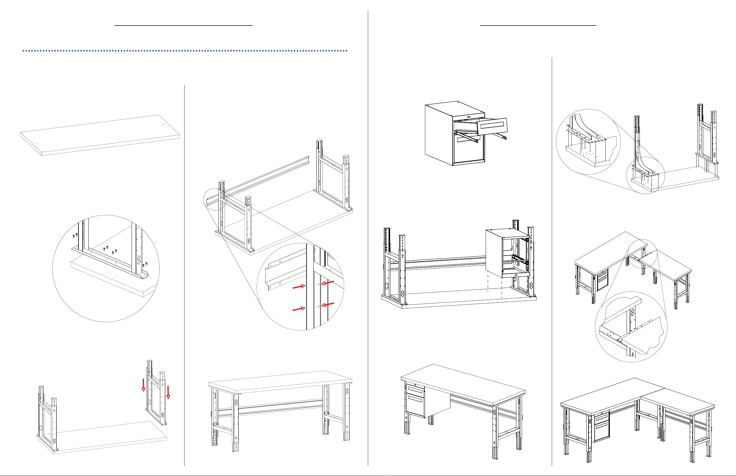
ASSEMBLY OF WORKSTATION
Two people are recommended for assembly. Approximate assembly time: 20-25 minutes.
The reference numbers used throughout this sheet refer to the illustration on the back cover.
This is to help you to identify the various parts as they are mentioned.
1. Lay the top (Ref. No. 1) face down on two sawhorses or
a protected at surface with the predrilled holes facing up.
2. Place an adjustable leg (Ref. No. 2) on one end of the
top, aligning it with the eight pre-drilled pilot holes.
Attach with eight #14 x 3/4” hex head slotted wood
screws (Ref. No. 8).
1. Remove the top drawer (A) from the housing (C) by rst
pulling it to the full extent that the suspensions allow.
Once the drawer is fully open, lift the drawer off the suspension
member to release the suspension sections. Follow the
same procedure with the bottom drawer (B).
NOTE: The stringer attaches to the
at area on the outside of each leg.
Use four bolts, nuts, and lockwashers
on each end of the stringer.
2. Using the housing as a template, mark locations of the
holes for the wood screws onto the underside of the wood
top. (Recommendation is ½” offset from front of wood
top.) Next, drill four holes ½” to ¾” deep into the wood
top using a 5
/
32” drill bit. Once you’re nished, secure the
housing to the top using four #14-¾” hex head slotted
wood screws.
5. If you purchased only the basic workstation, your work
is now complete. The remaining instructions show
assembly of the optional accessories.
4. Attach the stringer (Ref. No. 1) to the rear legs, skipping the
top two holes and using the next four holes from the top
of each leg. (The legs are symmetrical, so front and rear
of the bench will be determined by where youplace the
stringer.) Attach the stringer with four 1/4”-20 x 5/8” bolts,
lockwashers, and nuts (Ref. No’s. 8, 9, 10) on each side.
NBF • (800) 558-1010
3. Place the other adjustable leg on the opposite end
of the bench top, using the same procedure shown
in step 2.
NOTE: If attaching an optional drawer unit, you may want to leave the
bench in the upside-down position.
OPTIONAL ACCESSORIES
Drawer Unit Assembly
3. Now turn the table upright and place the drawers
(which were taken out in step 1) into the suspensions
in the housing. Your workstation with drawer is complete.
“L” Shape Leg Assembly
1. Turn the wood top face down. Using the holes in the
Leg Plates as a template, mark the locations on the
underside of the wood top for the wood screws. Then
using a 5
/
32” drill bit, drill eight holes into the top, about
½” to ¾” deep on each side. Next, secure each leg to the
top using eight #14-¾” hex head slotted wood screws per leg.
2. Turn the table over and line up with the already assembled
workstation to create an “L” shape. Once the tables are
together, drill four holes through the plate under the
assembled workstation and secure with four #14-¾”
wood screws.
3. Now your extended “L” shape workstation is nished!
(A)
(B)
(C)
For assembly and installation of an Electronic Riser, please refer to the instructions which came with the Riser Kit.
NOTE: After marking where the holes
need to be, move the drawer housing
to the side before drilling.
Popular Desktop manuals by other brands

HP
HP Pavilion dm4 Maintenance and service guide

Fujitsu
Fujitsu CELSIUS M4 Series operating manual

Lenovo
Lenovo ThinkCentre M70e Hardware Maintenance Manual

HP
HP 8000 - Elite Convertible Minitower PC Brochure & specs

HP
HP dx7400 - Microtower PC Illustrated parts & service map

HP
HP Presario All-in-One CQ1-1100 - Desktop PC Quick setup