Nematron MON-920 User manual

MON-920 17” Analog
Industrial Monitor
Users Guide
DOC-IWS-621
Revision A
DOC-IWS-621/A MON-920 Flat Screen Monitor User’s Guide
2
MON-920 Flat Screen Monitor
User’s Guide
DOC-IWS-621
Revision A
The MON-920 Industrial Flat Panel User’s Guide (DOC-IWS-621) describes the installation
and operation of these units. This document is based on information available at the time of
its publication. While every effort has been made to be accurate, the information contained
herein does not purport to cover all details or variations in hardware or` software. Nematron
makes no warranty and assumes no responsibility for the completeness, accuracy or
usefulness of the information found in these pages. Nematron further assumes no liability or
responsibility for loss or damage, direct or indirect, arising from the use of this product. No
warranties of documentation or product fitness apply.
Nematron, PowerVIEW, NemaSoft, AutoNet, and FloProare registered trademarks
of the Nematron Corporation. Industrial Control Computer, Industrial Workstation, and
FlexBox, are trademarks of Nematron Corporation.
All brand and product names are trademarks or registered trademarks of their respective
companies.
Electrical Shock Hazard! Do not operate the unit with its back cover removed.
There are hazardous voltages inside. Servicing of the equipment should only be
done by qualified and authorized personnel.
CAUTION! Changes or modifications not expressly approved by the manufacturer could void
the user’s authority to operate the equipment.
Note: The terminal must be mounted in a grounded metal enclosure that provides a clean
and dry environment.
Note: This equipment has been tested and found to comply with the limits for a Class B
digital device, pursuant to Part 15 of the FCC Rules. These limits are designed to provide
reasonable protection against harmful interference in a residential installation. This
equipment generates, uses, and can radiate radio frequency energy and, if not installed and
used in accordance with the instruction manual, may cause harmful interference to radio
communications. However, there is no guarantee that interference will not occur in a
particular installation. If this equipment does cause harmful interference to radio or television
reception, which can be determined by turning the equipment off and on, the user is
encouraged to try and correct the interference by one or more of the following:
Reorient or relocate the receiving antenna.
Increase the separation between the equipment and the receiver.
Connect the equipment to an outlet on a circuit different from that to which the
receiver is connected.
Consult the dealer or experienced radio/TV technician for help.
Customer Service: Contact your local Nematron Sales Representative. For assistance in
locating your local Sales Representative, call 734-214-2000. Also, visit us on the Web at
nematron.com.
Copyright 2001 by Nematron Corporation. All rights reserved. Printed in U.S.A.

DOC-IWS-621/A MON-920 Flat Screen Monitor User’s Guide
3
Table of Contents
Table of Contents...................................................................................... 3
Chapter 1 -- Introduction............................................................................ 4
1.1 General Information......................................................................... 4
1.2 Packing List ..................................................................................... 4
1.2 Specifications and Ratings............................................................... 5
1.3 MON-920 Dimensions...................................................................... 6
1.4 MON-920 Supplementary Views...................................................... 7
Chapter 2 -- Components, Connectors, and Pinouts................................. 8
2.1 AC Power Connector and Switch..................................................... 8
2.2 Cooling Fan ..................................................................................... 8
2.3 Video Connector.............................................................................. 9
2.4 Optional Serial Touch Connector..................................................... 9
Chapter 3 -- Installation and Setup.......................................................... 10
3.1 Installation Instructions .................................................................. 10
3.2 Connections and Power Up ........................................................... 10
3.4 Video Signal Adjustments.............................................................. 12
3.5 LCD Trouble Shooting Guide......................................................... 12
3.6 Using the Touchscreen.................................................................. 12
3.6.1 Installing and Calibrating in MS-DOS...................................... 13
3.6.2 Installing and Calibrating in Windows 95 and 98..................... 13
3.6.3 Installing and Calibrating in Windows NT 4.0.......................... 14
3.7 Replacing the Backlights................................................................ 14
3.8 Changing the Fuse......................................................................... 14
3.9 Cleaning or Replacing the Fan Filter.............................................. 15
Appendix – Adjusting Your MON-920...................................................... 16
Enter the Setup Mode ...................................................................... 16
BRIGHTNESS & CONTRAST.......................................................... 17
COLOR TEMPERATURE ................................................................ 17
FREQUENCY, PHASE, POSITION.................................................. 17
ZOOM .............................................................................................. 18
SHARPNESS................................................................................... 18
LANGUAGE ..................................................................................... 18
SOURCE.......................................................................................... 19
RGB SCALING................................................................................. 19
UTILITIES ........................................................................................ 20
DOC-IWS-621/A MON-920 Flat Screen Monitor User’s Guide
4
Chapter 1 -- Introduction
This chapter gives a complete physical description of your Flat Panel Monitor, including all
specifications and ratings.
1.1 General Information
The MON-920 is one of a family of analog flat panel monitors from Nematron. It accepts a
standard “VGA” signal from any PC. The resolution of the MON-920 is SXGA (1280 x 1024)
and it supports up to 16.7 million colors. Like all Nematron flat panel monitors, the MON-920
is NEMA 4/4X/12 rated, when properly mounted in a rated enclosure.
The standard cable kit supplied with the MON-920 allows the user to mount the monitor up to
20 feet from the computer. This is sometimes necessary due to environmental or space
restrictions. Nematron also supplies cable kits for using the monitor up to 75 feet from the
computer. Various companies (e.g., Black Box) offer kits for extending the signal distance
much further.
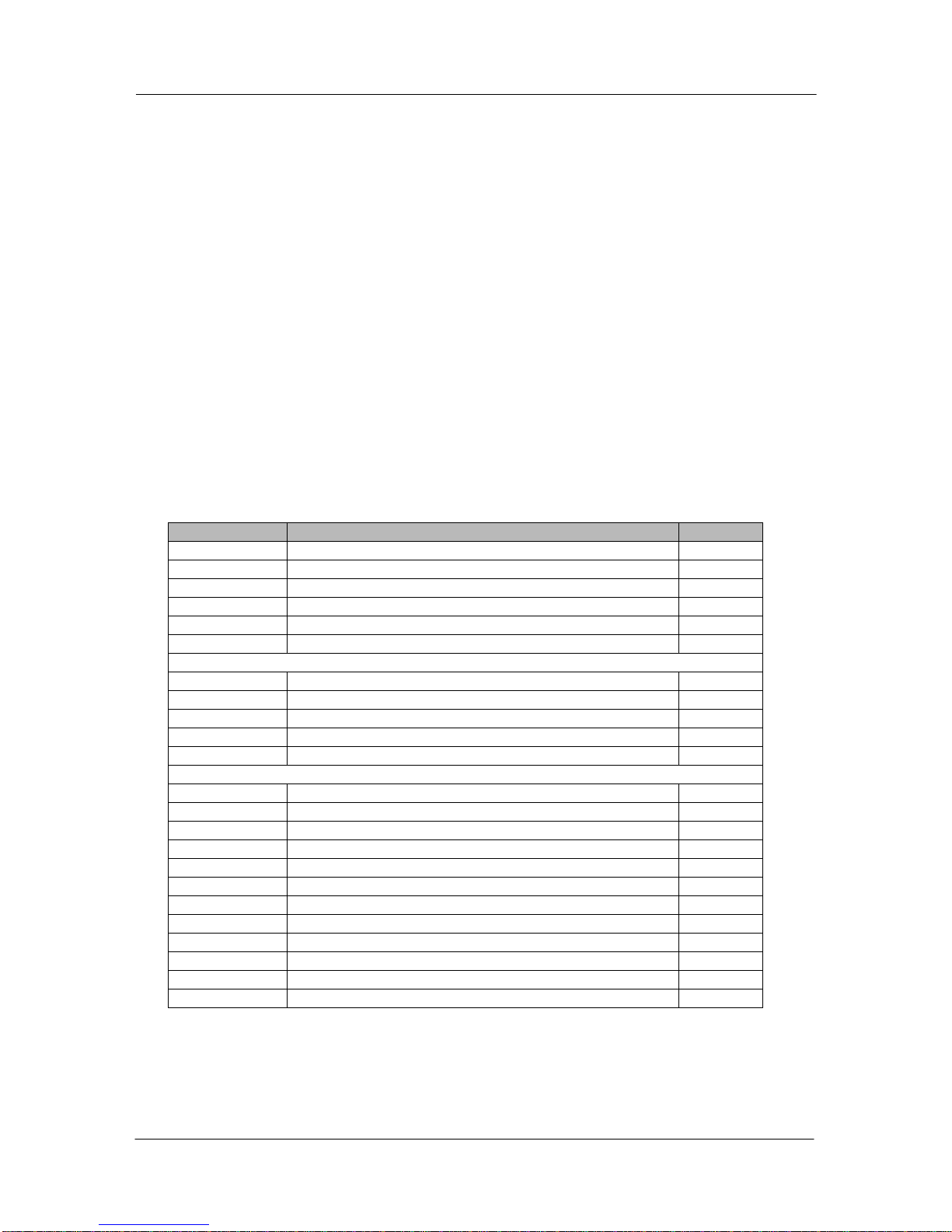
1.2 Packing List
MON-920 Flat Panel Monitors are shipped with the following parts and accessories:
Part Number Description Qty
n/a MON-920 Flat Panel Monitor 1
204A0006 Mounting clip 12
250A0135 Screw, 10-32 x 1.25” pan head 12
610A0007 AC power cord 1
DOC-IWS-026 Customer Registration Form 1
DOC-IWS-621 MON-920 Flat Screen Monitor User’s Guide 1
VGA CABLE
137A0049 20 foot video cable 1
OR
137A0054 50 foot video cable 1
OR
137A0052 75 foot video cable 1
ACCESSORIES ON UNITS W/TOUCH OPTION
854A0370 Touchscreen driver disk for Windows 3.1 1
854A0393 Touchscreen driver disk for Windows 95 1
854A0394 Touchscreen driver disk for OS/2 1
854A0696 Touchscreen driver disk for Windows NT 4.0 1
854A0697 Touchscreen driver disk for Windows 2000 1
854A0566 SkreenKleen program disk 1
DOC-IWS-570 SkreenKleen User’s Guide 1
137A0050 20 foot serial touch cable, 9-pin 1
OR
137A0055 50 foot serial touch cable, 9-pin 1
OR
137A0054 75 foot serial touch cable, 9-pin 1

DOC-IWS-621/A MON-920 Flat Screen Monitor User’s Guide
5
1.2 Specifications and Ratings
Display 17” SXGA Color TFT (1280 x 1024)
Overall Dimensions
(W x H x D) 18.25” x 16.00” x 4.27” (463.6 mm x 406.4 mm x 108.4 mm)
Cutout (W x H) 17.37” x 15.12” (441.2 mm x 384.0 mm)
Weight 27 lbs (12.2 kg)
Operator Input Optional Resistive Touchscreen
Power 85 to 230 VAC auto-ranging
Operating Temperature 32°F to 122°F (0°C to 50°C)
Operating Humidity 5% to 80% RH, non-condensing
Vibration 5 Hz to 500 Hz, 1 G
Shock Operational: 15 G, 11 msec
Non-operational: 30 G, 11 msec
EMC
FCC Part 15 Class A (Conducted and Radiated)
EN55022 Class A (Conducted and Radiated)
EN50082-2
CE Mark, EU EMC Directive 89/336/EEC
Safety Compliance UL-508
CSA C22.2, No 14-M91 (cUL)
CE Mark, EU Low Voltage Directive 73/23/EEC
DOC-IWS-621/A MON-920 Flat Screen Monitor User’s Guide
6
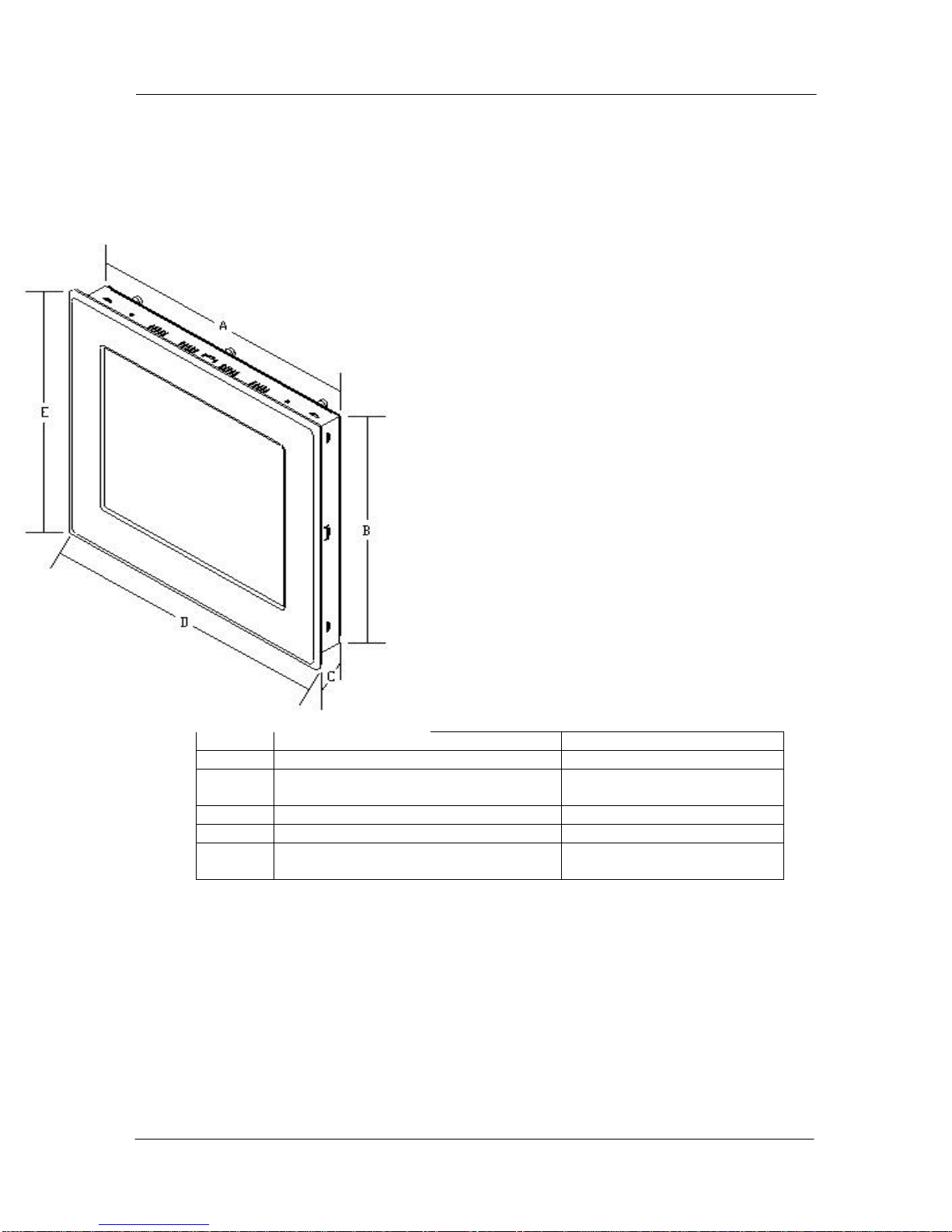
1.3 MON-920 Dimensions
Isometric view with dimensions
(see table below)
A Chassis Width 17.26” (438.4 mm)
B Chassis Height 15.00” (381.0 mm)
CChassis Depth (including
power/connector module) 4.13” (104.9 mm)
D Bezel Width 18.25” (463.6 mm)
E Bezel Height 16.00” (406.4 mm)
Cutout 17.38” W x 15.12” H
(441.4 mm x 384.0 mm)
DOC-IWS-621/A MON-920 Flat Screen Monitor User’s Guide
7
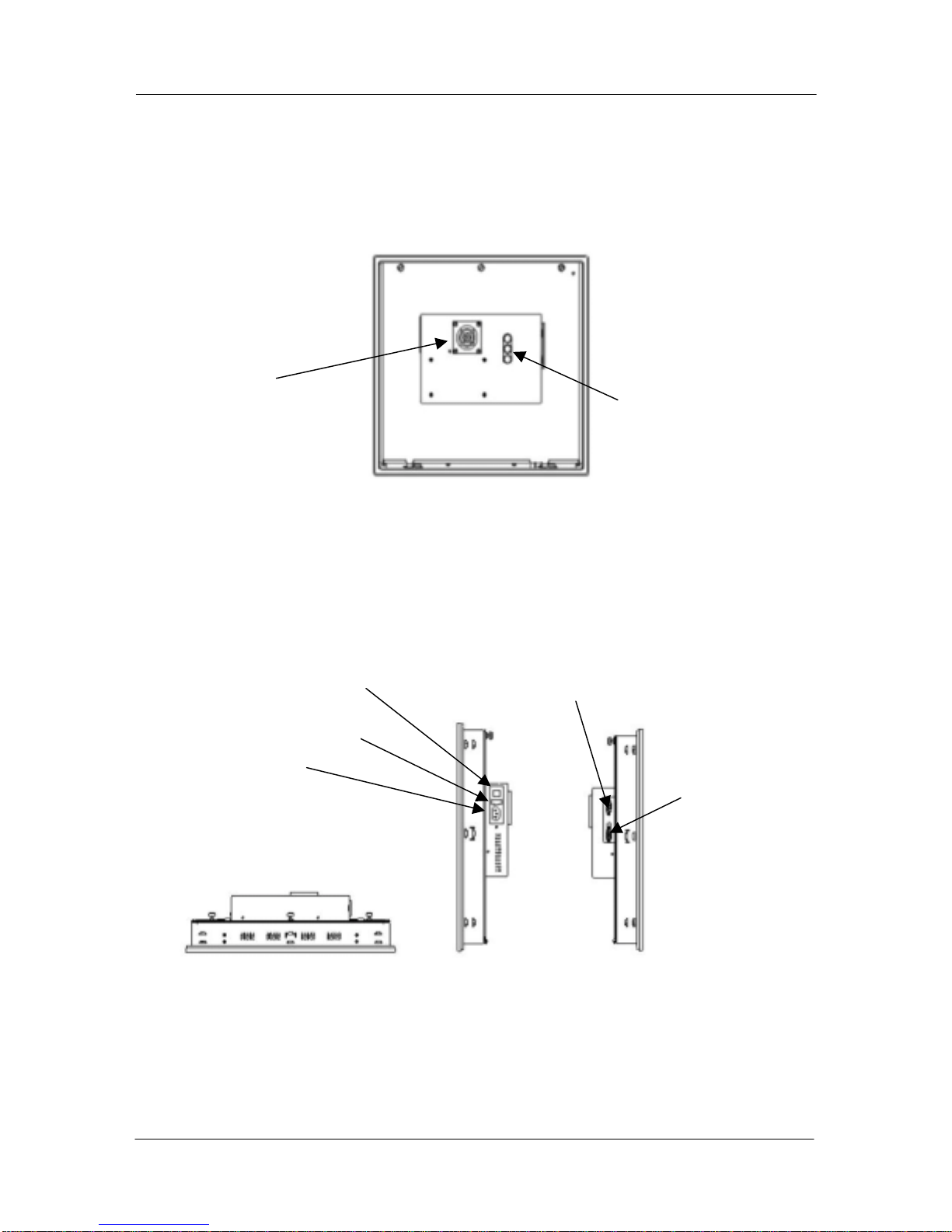
1.4 MON-920 Supplementary Views
MON-920 Rear View
MON-920 Top and Side Views
Adjustment
Controls
Chassis Fan
Video
Connector
Optional Serial
Touch Connector
AC Power
Connector
AC Power Switch
Fuse

DOC-IWS-621/A MON-920 Flat Screen Monitor User’s Guide
8
Chapter 2 -- Components, Connectors, and Pinouts
This chapter describes the components and connectors of your flat panel monitor.
Warning! Make sure your monitor is powered down and unplugged before
removing the cover or working on internal components.
Warning! Make sure your monitor is grounded at all times. Also make sure that it
is on the same ground as any other equipment connected to its communications
ports.
2.1 AC Power Connector and Switch
The 110/220 VAC power connector is located on the right side panel of the unit, as shown in
the side views figure. This module is rated only for non-hazardous locations. See section 3.2
on page 9 for power up information.
On the AC power switch, “1” indicates Power ON and “0” indicates Power OFF.
If necessary, the 2.5A 250V Slo-Blo fuse can be replaced according to the instructions given
in section 3.8 on page 12.
2.2 Cooling Fan
The fan which cools the unit is located on the rear panel, as shown in the rear view figure.
The fan housing is secured to the unit case with four Philips-head screws, and the fan filter is
located inside the housing. Clean or replace the fan filter as needed according to the
instructions in section 3.9.

DOC-IWS-621/A MON-920 Flat Screen Monitor User’s Guide
9
2.3 Video Connector
The video connector is located on the left side panel of the unit, as shown in the side views
figure. The connector is a mini DB15.
Pin # Function
1Red
2 Green
3Blue
4N/C
5 Ground
6 Ground
7 Ground
8 Ground
9N/C
10 Ground
11 N/C
12 N/C
13 H-Sync
14 V-Sync
15 N/C
2.4 Optional Serial Touch Connector
If your unit is equipped with serial resistive touch, this mini DB9 connector will be on the left
side of the unit.
Pin Signal Name Function
1 DCD Data Carrier Detect
2 RXD RS-232 Receive Data
3 TXD RS-232 Transmit Data
4 DTR Data Terminal Ready
5 GND Ground
6 DSR Data Set Ready
7 RTS Request to Send
8 CTS Clear to Send
9 RI Ring Indicator
DOC-IWS-621/A MON-920 Flat Screen Monitor User’s Guide
10
Chapter 3 -- Installation and Setup
Remove your unit from the packaging and set it up according to the instructions in this
chapter. Included in this chapter are instructions for:
Installing the unit in a panel
Making connections and powering the unit up
Adjusting the video signal
Using the touchscreen
Changing the fuse
Cleaning and/or replacing the filter
3.1 Installation Instructions
Warning! Failure to follow the instructions for your unit could result in injury to
personnel or damage to equipment.
Follow the instructions below to install your Flat Screen Monitor.
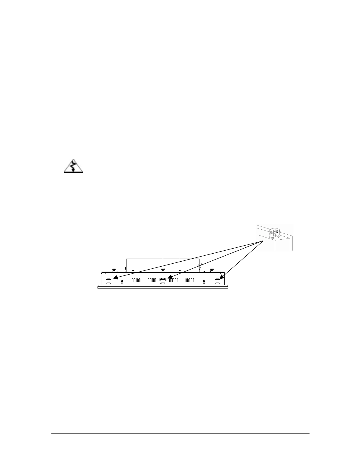
1. Position the unit in the cutout in your panel.
2. From the rear of the unit, insert the mounting clips into the slots on the top, bottom,
and sides of the unit. Twelve mounting clips and screws are provided with the unit.
3. Tighten the twelve mounting clip screws in a criss-cross pattern, each a little at a time
until five to seven inch-pounds of torque is reached on each screw. Do not tighten
any one screw completely at one time. The result could be an inadequate seal or
deformation of the front chassis.
3.2 Connections and Power Up
Refer to the “Specifications and Ratings” table in Chapter 1 for AC power ratings. Follow the
procedure below to connect and power up the unit.
1. Verify that the power to the unit is turned off. On the AC power switch, 1 indicates
Power ON and 0 indicates Power OFF.
2. Verify that the power to the computer you’re hooking the monitor up to is turned off.
3. Use the supplied video cable to connect the video output of the computer to the
monitor. If your monitor has the touch option, attach the supplied serial cable to the
monitor and to one of the computer’s serial ports. You’ll need to know which serial

DOC-IWS-621/A MON-920 Flat Screen Monitor User’s Guide
11
port you used when installing the touch drivers. Serial ports are usually labeled
COMx, where x is a single digit number. Refer to the drawings in sections 1.4, 2.3,
and 2.4.
4. Plug the supplied AC power cord into an outlet and then into the “AC Power
Connector” socket on the side of the flat screen monitor (refer to the “Side View”
drawings in Section 1.4). The AC power cord provides the necessary earth
grounding for safety.
5. The unit is now ready to power up. Turn on the computer and flip the monitor’s
power switch into the “1” position.
DOC-IWS-621/A MON-920 Flat Screen Monitor User’s Guide
12
3.4 Video Signal Adjustments
Video signal adjustments are made using the 3-position membrane switch on the rear of the
unit (refer to the “Rear View” drawing in Section 1.4). Detailed instructions are in the
Appendix.
3.5 LCD Trouble Shooting Guide
Symptom Possible Causes Actions
No LCD display
image
•No power
•No video signal
•Problem with the
backlights
•Verify that the Power On LED is lit.
•Check to see that the video source
is on and operating, perhaps using
another monitor.
•Verify that the backlight cables are
properly connected. Check
whether the backlights need
replacing.
Half of the image
is dark •Problem with the
backlights
•Verify that the backlight cables are
properly connected.
•Check whether one of the
backlights needs replacing.
LCD image is too
bright or white
•Adjustments
•Unrecognizable sync
patterns
•Reset the factory default settings
(see Appendix)
•Verify the supplied video format.
The monitor recognizes only
640x480, 800x600, 1024x768, &
1280x1024 PC formats.
LCD image is not
centered
•Adjustments
•Unrecognized video
format
•Adjust the positioning (see
Appendix)
•Verify the supplied video format.
The monitor recognizes only
640x480, 800x600, 1024x768, &
1280x1024 PC formats.
Configuration
changes not
accepted by the
monitor
•Adjustments
•When making adjustments, be sure
to “back out” of the adjustment
menus up to the MAIN MENU level
(see Appendix).
Display image
jitters or flickers •Adjustments •Adjust Phase and frequency for
best image (see Appendix)
3.6 Using the Touchscreen
For the MON-920, the touchscreen should be configured to emulate a mouse input device.
Your system is supplied with a touchscreen driver disk set. This disk set contains all of the
appropriate drivers to configure the touchscreen for your applications. To install the
touchscreen drivers, follow the instructions or your operating system below:

DOC-IWS-621/A MON-920 Flat Screen Monitor User’s Guide
13
3.6.1 Installing and Calibrating in MS-DOS
1. Insert the driver disk for MS-DOS in the diskette drive.
2. From the command prompt, type A:\INSTALL and press Enter.
3. Follow the prompts on the screen until you are asked to specify the installation
parameters. Choose DOS Express.
4. Choose Serial.
5. Choose the serial port (COM 1 or COM2) to which the touchscreen serial cable is
connected.
6. Press Enter. The driver files are loaded.
7. Follow the prompts in the screen until you return to the command prompt.
8. Eject the diskette from the drive.
9. Type C:\GO and press Enter.
10. On the flat screen monitor, touch the calibration points as indicated.
The touchscreen drivers are now installed and calibrated. To recalibrate the touchscreen at
any time, repeat steps 9 and 10 above.
3.6.2 Installing and Calibrating in Windows 95 and 98
1. Insert the Windows 95 touchscreen driver disk into the diskette drive.
2. Choose Start > Run.
3. Type A:\SETUP and press Enter.
4. Follow the prompts on the screen until you are asked to choose the COM port.
Choose the serial port (COM 1 or COM2) to which the touchscreen serial cable is
connected.
5. Click OK.
6. Eject the Disk from the drive and click YES to restart the computer. Your computer
will boot directly into the calibration procedure.
7. On the flat screen monitor, touch the calibration points as indicated.
8. Click OK to save your changes and close the window. Note: If you close the
window by clicking the “X” in the upper right corner of the window, your
changes WLL NOT be saved.
The touchscreen drivers are now installed and calibrated. To recalibrate the touchscreen at
any time:
1. Choose Start > Settings > Control Panel.
2. Double-click on ELOTOUCH.
3. Choose Calibrate.
4. On the flat screen monitor, touch the calibration points as indicated.
5. Click OK to save your changes and close the window. Note: If you close the
window by clicking the “X” in the upper right corner of the window, your
changes WLL NOT be saved.

DOC-IWS-621/A MON-920 Flat Screen Monitor User’s Guide
14
3.6.3 Installing and Calibrating in Windows NT 4.0
1. Insert the Windows NT touchscreen driver disk into the diskette drive.
2. Choose Start > Run.
3. Type A:\SETUP and press Enter.
4. Follow the prompts on the screen until you are asked to launch the ELO Wizard and
click OK.
5. Choose Serial.
6. Choose SmartSet 2xx0.
7. Choose the serial port (COM 1 or COM2) to which the touchscreen serial cable is
connected.
8. Click OK.
9. Eject the Disk from the drive and restart your computer.
10. Choose Start > Settings > Control Panel.
11. Double-click on ELOTOUCH.
12. Choose Calibrate.
13. On the flat screen monitor, touch the calibration points as indicated.
14. Click OK to save your changes and close the window. Note: If you close the
window by clicking the “X” in the upper right corner of the window, your
changes WLL NOT be saved.
The touchscreen drivers are now installed and calibrated. To recalibrate the touchscreen at
any time, repeat steps 10 through 14 above.
3.7 Replacing the Backlights
LCD backlights are rated at the number of hours of operation until they are at half of their
original brightness. The MON-920 backlights are rated at 50,000 hours – almost 6 years of
continuous service. A backlight replacement kit can be ordered from Nematron (part number
COS-BKL-17/L01). Call 800.NEMATRON and ask for Customer Care. There may be a
minimum order charge. Instructions for changing the backlights are included in the kit.
Signs that the backlights may need replacing include:
The top and/or the bottom of the screen is dim.
The image on the screen flickers.
The video appears to be blank in normal light, but can be very faintly seen in strong
external light.
3.8 Changing the Fuse
The 2.5A 250V Slo-Blo fuse and one spare fuse are located between the power switch and
the AC socket on the right side of the unit. To replace the fuse:
1. Make sure the fat screen monitor is turned off.
2. Disconnect the power cord from the flat screen monitor.
3. With a small flat head screwdriver, pry the fuse compartment out of the black plastic

DOC-IWS-621/A MON-920 Flat Screen Monitor User’s Guide
15
housing.
4. Remove the blown fuse from the fuse compartment.
5. Insert a new fuse of exactly the same rating into the fuse compartment.
6. Replace the fuse compartment into the black plastic housing.
7. Reconnect the AC power cord to the unit.
8. The unit is now ready to power on.
3.9 Cleaning or Replacing the Fan Filter
The fan is located on the back of the flat screen monitor. The filter should be cleaned or
replaced as needed, depending on the operating environment in your facility. Replacement
filters are available from Nematron (part number 272A0012). Call 800.NEMATRON and ask
for Customer Care. There may be a minimum order charge.
To clean or replace the filter:
1. Verify that the flat screen monitor is powered off.
2. Using a small flat head screwdriver, carefully pry the fan grill out of the fan housing,
taking care not to pierce the filter.
3. Remove the filter. Rinse the filter and dry it thoroughly. Also clean the fan grill, if
necessary.
4. Replace the filter and pop the fan grill back into place.
5. The unit is ready to power on.
DOC-IWS-621/A MON-920 Flat Screen Monitor User’s Guide
16
Appendix – Adjusting Your MON-920
Your MON-920 was adjusted by Nematron before it was shipped. It may not be necessary to
make any further adjustments. If you need to make adjustments, they can be performed at
any time using the 3-position membrane keypad on the back of the unit. The button functions
are very straightforward:
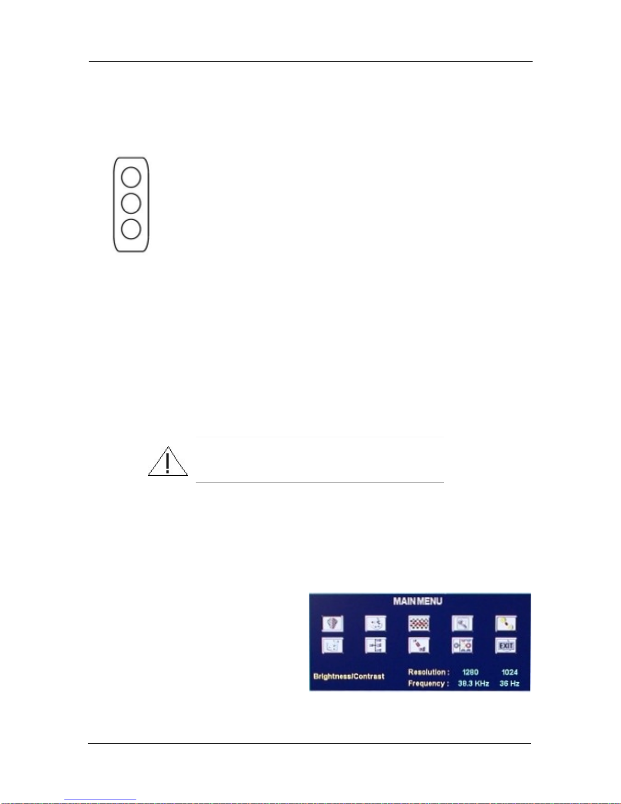
TOP – Use this button to enter the Setup Mode. While in the Setup Mode, use
this button to select the highlighted choice.
MIDDLE – Use this button to move UP or to the LEFT among displayed choices.
BOTTOM – Use this button to move DOWN or to the RIGHT among displayed
choices.
The routine for changing values is the same throughout the Setup Mode.
To scroll through options use the middle and bottom buttons. As you move
through them they are highlighted in succession.
To select an option press the top button when the option is highlighted.
To choose from a list of fixed values scroll through them by using the middle and
bottom buttons and, when the preferred choice is highlighted, select it by using the
top button. An example of this is the LANGUAGE menu.
To set a value using a “slider” “highlight” the slider and “select” it, as described
above. Use the middle and bottom buttons to move the slider to the desired value
and lock that value in by pressing the top button. An example of this is the
BRIGHTNESS & CONTRAST menu.
Important! Always return to the MAIN MENU after
changing any values or selections.
Enter the Setup Mode
Press the top button on the keypad. The MAIN MENU screen will appear. Scroll through the
icons using the middle and bottom buttons on the keypad. The functions indicated by the
icons, from left to right, are:
Upper Row
BRIGHTNESS & CONTRAST
COLOR TEMPERATURE
FREQUENCY, PHASE, POSITION
ZOOM
SHARPNESS
Bottom Row
LANGUAGE
SOURCE
RGB SCALING
UTILITIES
EXIT
As you scroll through the icons, the function of the highlighted icon appears in the lower left
corner of the menu.
DOC-IWS-621/A MON-920 Flat Screen Monitor User’s Guide
17
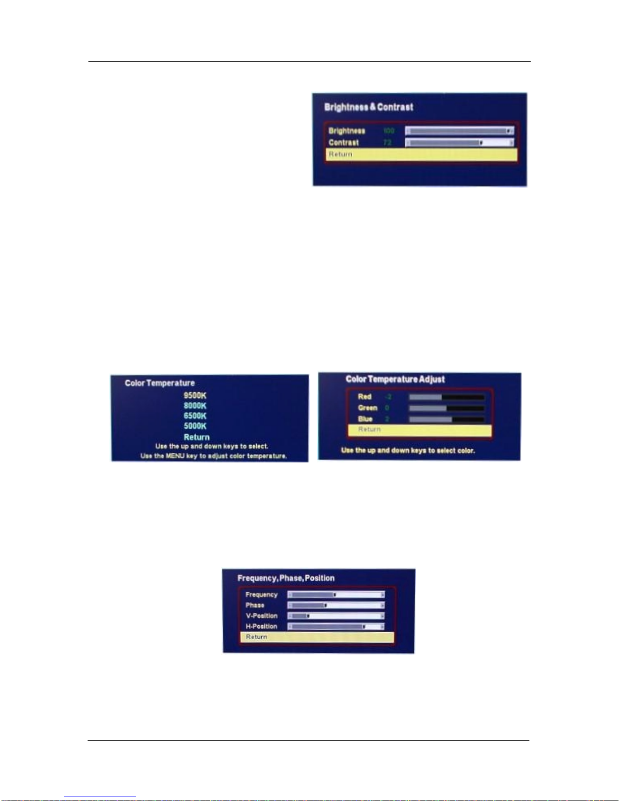
BRIGHTNESS & CONTRAST
Selecting the BRIGHTNESS &
CONTRAST icon brings you to the
function display on the right. Contrast
deals with the difference between the
lighter and darker elements in an image.
Brightness is the overall intensity of the
image. To change the values in this sub-
menu:
1. Use the middle or bottom button to highlight either the Brightness or Contrast scale
and press the top button to select
2. Use the middle and bottom buttons to adjust the slider to the desired new value.
3. Lock that value in by pressing the top button.
4. Repeat steps 1 to 3 to make other changes, if desired.
5. When you are finished, use the middle or bottom button to highlight “Return” and
press the top button to return to the main menu.
COLOR TEMPERATURE
Use these sub-menus to adjust the color, if necessary. Use the first sub-menu to select a
temperature value and the second sub-menu to make RGB adjustments within that
temperature value.
FREQUENCY, PHASE, POSITION
Adjust the frequency setting to the highest value that gives a good image. Use the phase
adjustment to minimize any jitter you might be seeing in the display. This will be most evident
in the vertical lines of the image. The position adjustments are used to center the image in
the display.
DOC-IWS-621/A MON-920 Flat Screen Monitor User’s Guide
18
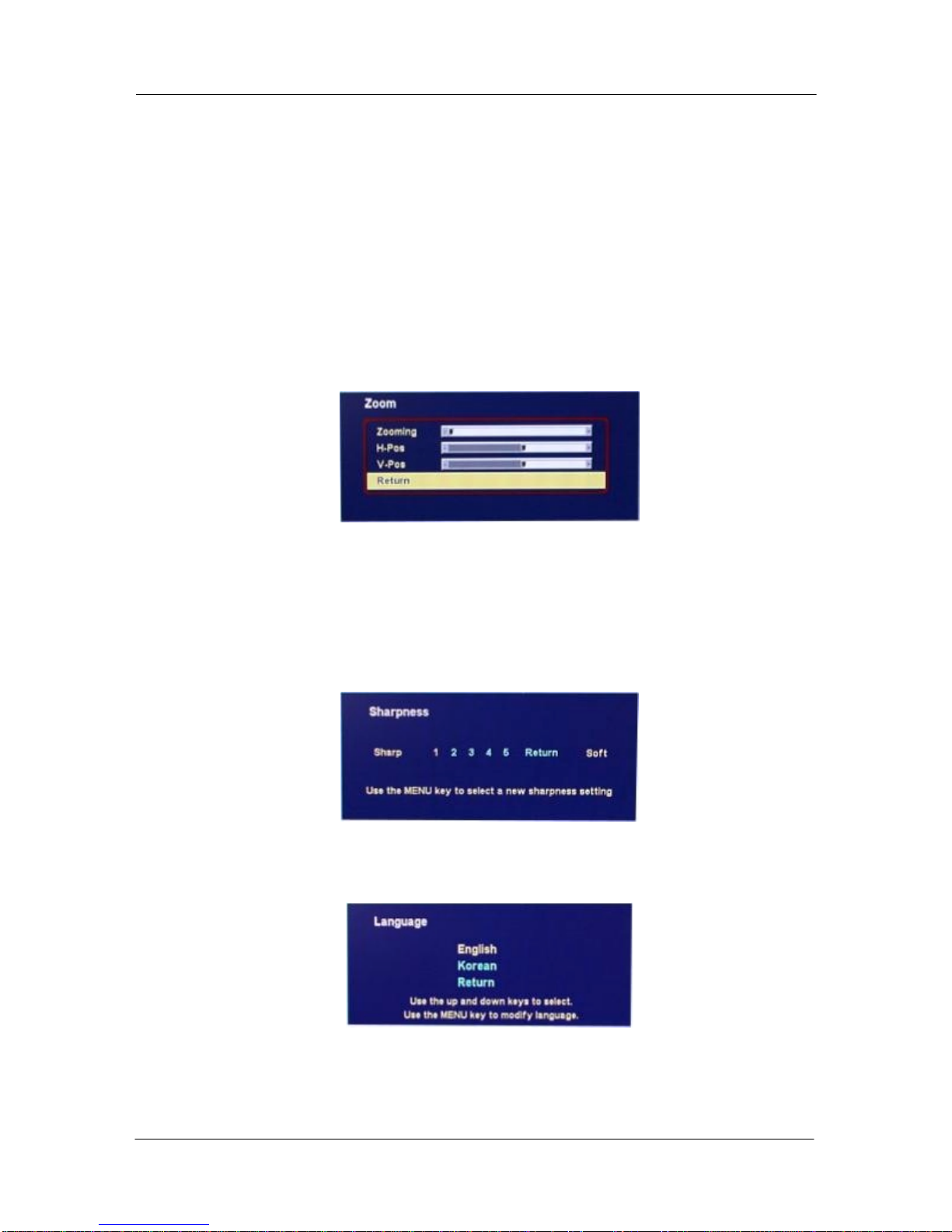
ZOOM
The Zoom menu allows you to “zoom” in on (or magnify) a section of a displayed image. Use
the “Zooming” slider to choose the amount of magnification, and the “H-Pos” (horizontal) and
“V-Pos” (vertical) sliders to choose which part of the image to display. To adjust the zoom,
1. Use the middle or bottom button to highlight one of the 3 sliders and press the top
button to select
2. Use the middle and bottom buttons to adjust the slider to the desired new value.
3. Lock that value in by pressing the top button.
4. Repeat steps 1 to 3 to make other changes, if desired.
5. When you are finished, use the middle or bottom button to highlight “Return” and
press the top button to return to the main menu.
SHARPNESS
The MON-920 allows you to adjust the sharpness of the display. Sharpness is somewhat
subjective and the optimal sharpness depends on the user and the application. Sharpness
adjustments should be done with a representative image displayed. If the images are too
varied, set the sharpness for an image with small features (e.g., desktop icons) and then
check the results on an image with larger features. Choose a sharpness setting that yields
the best overall image.
LANGUAGE
Choose between English and Korean language menus.
DOC-IWS-621/A MON-920 Flat Screen Monitor User’s Guide
19
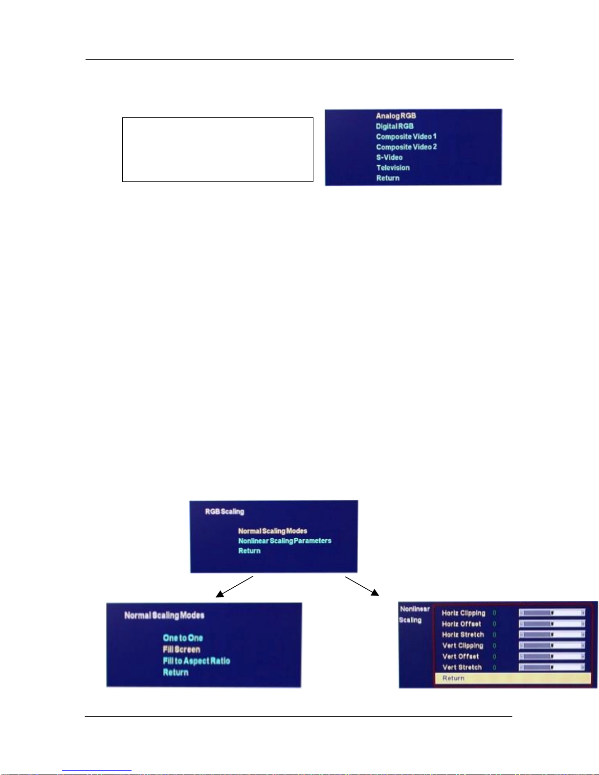
SOURCE
The only valid choice for the
MON-920 is Analog RGB.
!!! DO NOT MAKE ANY
CHANGES IN THIS MENU !!!
If a source other than “Analog RGB” is chosen, the display will turn a solid color and check for
a signal on the non-existent source. To recover, remove the rear cover from the unit and
press the fourth button several times until the source choices begin flashing on the display.
Scroll through the choices, using the middle or bottom button, until the image comes back.
RGB SCALING
WE RECOMMEND THAT YOU MAKE NO CHANGES TO THE FACTORY SETTINGS
UNDER THE “Nonlinear Scaling Parameters” CHOICE IN THIS MENU.
Under the “Normal Scaling Modes” choice in this menu, there are three choices:
One to One – The MON-920 has an SXGA (1280 pixels x 1024 pixels) flat panel display. If
you choose “One to One” AND the resolution on your computer is set to something
less than 1280 x 1024, you will see a black band around your image because the MON-920
is showing the image in the lower resolution. If you choose “One to One” AND your
resolution is set to something more than 1280 x 1024, you will see only a portion of the
image generated on the computer. You can adjust resolution in Windows 9x/NT/2000 by
choosing Control Panel > Display > Settings from the START menu.
Fill Screen (THIS IS THE FACTORY SETTING AND WILL BE THE BEST SETTING FOR
MOST APPLICATIONS) – With this setting, the image generated by your computer fills the
screen on the MON-920.
Fill to Aspect Ratio – The aspect ratio of the MON-920 display is 5 : 4 (1280/1024 = 5/4). If
you choose this option AND the aspect ratio of the image generated by the computer is
different, you will see black bands at the top and bottom of the image or at the sides of the
image.

DOC-IWS-621/A MON-920 Flat Screen Monitor User’s Guide
20
UTILITIES
The only items of interest in the Utilities menu are the “User Settings” and the selections.
Use the Horizontal and Vertical sliders under “User Settings” to adjust the position of the
image on the display. These settings are very stable and should not require adjustment after
the initial installation.
The “Reset to factory defaults” selection resets the unit to the settings as they were when the
unit shipped.
Table of contents


