Nematron M1500 User manual

User’s Guide
M1500 / M1500T
15.0” XGA TFT NEMA 4/12
Flat Panel Monitor
Document No. DOC-IWS-712B, Rel. 4-2007

Revision List
Revision Number Description of Change Release Date
A Initial Release 9-2006
B Added Windows Vista driver to list of supported drivers, Added
notes to driver list, Changed Logo, Corrected H X W Reversals on
page 5
4-2007
Nematron reserves the right to make changes in specifications described herein at any time without
notice in order to improve design and reliability. Nematron does not assume any responsibility for
the use of any circuitry described; no circuit patent licenses are implied. Nematron assumes no
responsibility for damage caused by misuse or improper use of its products.
WARRANTY
Nematron warrants to Customer that the Products will be free from defects in material and
workmanship under normal use and service for a period of two years from date of invoice. Customer’s
exclusive remedy for breach of this warranty is that Nematron will either (i) repair or replace, at its option,
any Product which fails during the warranty period because of such defect (if Customer promptly reported
the failure to Nematron in writing) or, (ii) if Nematron is unable to repair or replace, Nematron will refund
the purchase price of the Product upon its return to Nematron. This warranty does not apply to any
Product which has been subjected to misuse, abnormal service or handling, or which has been altered or
modified in design or construction, or which has been serviced by anyone other than Nematron. The
warranty set forth herein is in lieu of, and exclusive of, all other warranties, express or implied.
Document No. DOC-IWS-712B M1500 / M1500T User Manual
Released 4-2007
2

3
Table of Contents
WARRANTY .............................................................................................................................................. 2
Table of Contents ...................................................................................................................................... 3
Chapter 1 - Introduction ................................................................................................................................ 4
Features .................................................................................................................................................... 4
Supported PC Video Modes...................................................................................................................... 4
Specifications ............................................................................................................................................ 5
DISPLAY................................................................................................................................................ 5
TOUCH SCREEN (Optional) ................................................................................................................. 5
PHYSICAL ............................................................................................................................................. 5
ELECTRICAL......................................................................................................................................... 5
ENVIROMENTAL................................................................................................................................... 6
AGENCY................................................................................................................................................ 6
Front and Side Views of Monitor ............................................................................................................... 6
Chapter 2 - Installation of Monitor................................................................................................................. 7
Cutout Pattern for M1500 / M1500T Monitor............................................................................................. 7
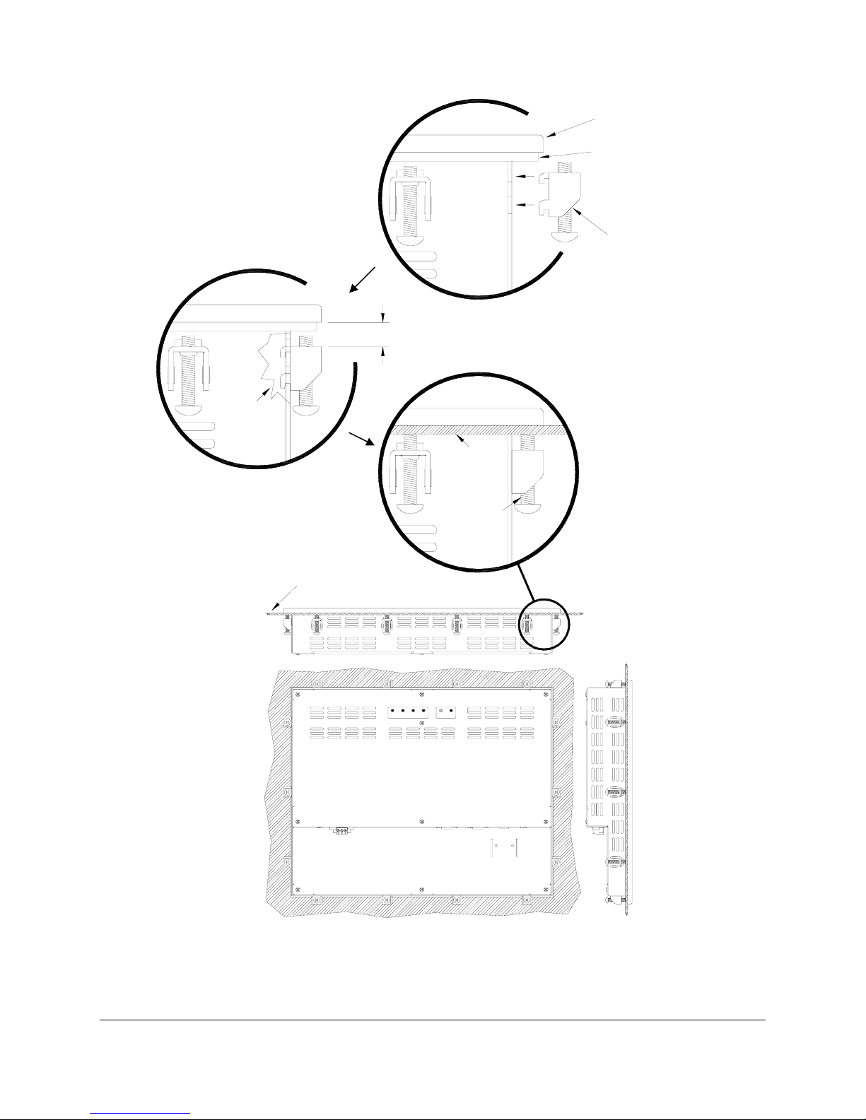
Mounting Clip Installation .......................................................................................................................... 8
Connecting Power ..................................................................................................................................... 9
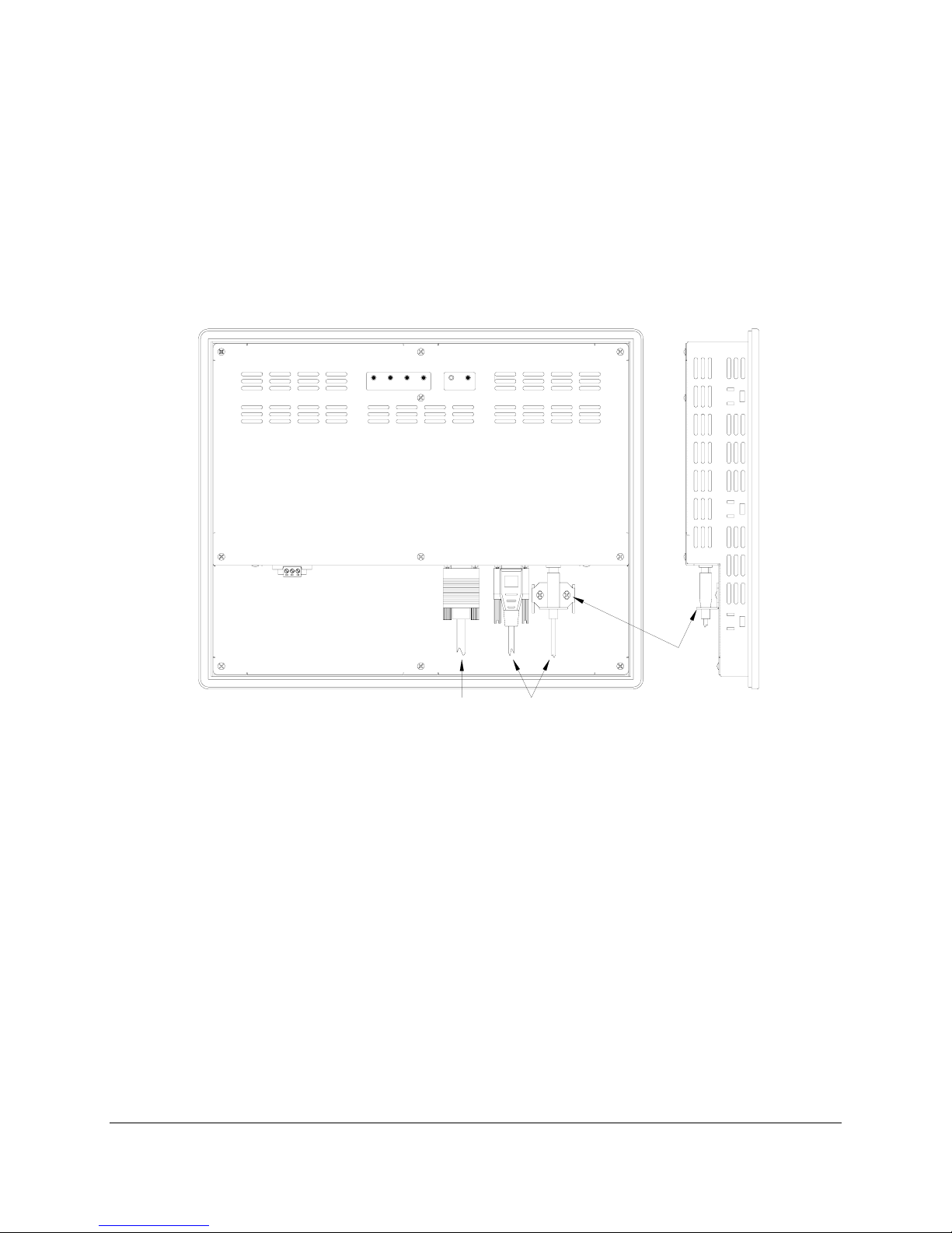
Connection of VGA and Touch Screen Cables.......................................................................................10
Turning on the Computer and Monitor .................................................................................................... 10
Selection of PC Video Settings ............................................................................................................... 10
Installing the Touch Screen Driver Software........................................................................................... 11
Chapter 3. - Monitor OSD and Settings ...................................................................................................... 12
On Screen Display (OSD) Controls......................................................................................................... 12
Button and LED Functions....................................................................................................................... 13
OSD Menus and Settings ........................................................................................................................ 14
MAIN MENU ........................................................................................................................................ 14
BRIGHTNESS/CONTRAST................................................................................................................. 14
COLOR ................................................................................................................................................ 16
POSITION............................................................................................................................................ 17
SETUP ................................................................................................................................................. 19
OSD Message Displays........................................................................................................................... 21
OUT OF FREQUENCY........................................................................................................................ 21
NO SIGNAL ......................................................................................................................................... 21
POWER SAVER MODE ...................................................................................................................... 21
PROCESSING AUTO CONFIGURATION........................................................................................... 22
Appendix ..................................................................................................................................................... 23
VGA Pin Assignment ............................................................................................................................... 23
Analog 15- Pin D-Sub .......................................................................................................................... 23
Touch Screen Pin Assignment ................................................................................................................ 24
Serial RS-232....................................................................................................................................... 24
USB...................................................................................................................................................... 24

Chapter 1 - Introduction
The M1500 is a high performance 15” color TFT flat panel monitor specifically designed for harsh
industrial environments including Class I & II, Division 2 Hazardous Locations. The M1500 accepts
standard analog VGA input and can display all VESA video modes up to 1280 x 1024 at 75Hz with 16
million colors. An optional 5-wire analog touch screen is available that offers both RS-232 and USB
interface capability. The monitor is housed in a heavy duty steel chassis with a powder coated machined
aluminum bezel. The monitor is certified to NEMA 4/4X/12 standards, is UL/CUL listed, meets CE
requirements and is RoHS compliant. Panel mounting is simplified using convenient mounting clips
instead of conventional studs. Options include: a 5-wire analog resistive touch screen, a 304 stainless
steel bezel and 24 volt DC input power. All monitors are shipped with a power input wiring receptacle,
VGA cable, touch screen cable (if equipped), mounting hardware, manual and driver software.
Features
•UL 508 and UL 1604 listed for Hazardous Locations: Class I, Division 2, Groups A, B, C, D and
Class II, Division 2, Groups F and G
•NEMA 4/4X/12 front bezel
•2-Year warranty
•RoHS Compliant
•Integral 100 -240 VAC power supply
•Simplified installation with no studs
•Thin design – Only 2.4” behind bezel
•Accepts analog 15-pin Video input
•VESA compliant – all modes up to SXGA, 75Hz
•Optional 5-wire resistive touch screen with both RS-232 and USB interface
•Optional 304 stainless steel front bezel
•Optional 24 VDC input power
Supported PC Video Modes
Mode Dot Clock
(MHz) Horizontal Freq
(KHZ) Vertical Freq (Hz) H Sync
Polarity V Sync
Polarity
640 x 350 @ 70Hz 25.144 31.430 70.000 P N
640 x 400 @ 70Hz 28.287 31.430 70.000 N P
720 x 400 @ 70Hz 28.287 31.430 70.000 N P
640 x 480 @ 60Hz 25.175 31.469 59.940 N N
640 x 480 @ 72Hz 31.500 37.861 72.809 N N
640 x 480 @ 75Hz 31.500 37.500 75.000 N N
800 x 600 @ 56HZ 36.000 35.156 56.250 P P
800 x 600 @ 60Hz 40.000 37.879 60.317 P P
800 x 600 @ 72Hz 50.000 48.077 72.188 P P
800 x 600 @ 75Hz 49.500 46.875 75.000 P P
1024 x 768 @ 60Hz 65.000 48.363 60.005 N N
1024 x 768 @ 70Hz 75.000 56.476 70.070 N P
1024 x 768 @ 75Hz 78.750 60.023 75.030 P P
1280 x1024 @ 60Hz 108.000 63.981 60.020 P P
1280 x 1024 @ 75Hz 135.000 79.976 75.035 P P
Note: The above highlighted PC display modes produce the best image quality on the M1500.
4

Specifications
DISPLAY
Display Size (Active Area H x V) 11.97” x 8.98”
Native Resolution XGA, 1024 x 768
VESA Modes Supported Up to 1280 x 1024 @75Hz
Displayable Colors 16M
Brightness, Typical 250 Nit
Contrast Ratio, Typical 550:1
Horizon/Vertical View Angle, CR>5, Typical 160°/140°
Backlight Life 40,000 hrs, Minimum
Display Input Signal Analog 15-Pin D-Sub
TOUCH SCREEN (Optional)
Touch Screen Technology 5- Wire Analog Resistive
Interface USB 1.1 and Serial RS-232
Resolution 4096 x 4096
Positional Accuracy (Maximum Error) .18”
Positional Accuracy (Standard Deviation of Error) <.08”
Expected Life >35,000,000 Activations
PHYSICAL
Over All Monitor Dimensions (H x W x D) 12.80” x 15.80” x 2.65”
Cutout Dimensions (H x W) 12.00” x 15.00”
Weight 12.5 lbs
Shipping Weight 15 lbs
ELECTRICAL
AC Input Voltage 100 – 240 VAC, 50/60 Hz
AC Input Current .5A Maximum
DC Input Voltage (Optional) 18 – 36 VDC
DC Input Current (Optional) .75 A Max @ 24VDC
Input Power ≤20W
5

ENVIROMENTAL
Operating Temperature 0°C to 50°C
Operating Humidity 20% to 80% RH, noncondensing
Operating Shock 15g peak acceleration, 11msec
Operating Vibration 5-2000 Hz 0.006” peak to peak, 1g max
Operating Altitude Sea level – 10,000 feet
AGENCY
Front Panel NEMA Rating NEMA 4/4X/12, IP65
FCC 47 CFR, Part 15, Class A
EU CE Marking Compliance CE, EN 55022: Class A,
EN 61000-3-2: Class A,
EN 61000-3-3, EN 61000-6-2,
Safety Agency Approvals UL 508 Listed, UL 1604 Listed*, cUL
Listed CSA C22.2, #142, CSA
C22.2, #143*
* Class I Division 2, Groups A, B, C, D; Class II, Division 2, Groups F and G
6
3
2
1
15.8"
12.8"
2.4"
2.65"
Front and Side Views of Monitor

Chapter 2 - Installation of Monitor
7
15.0"
±.02"
12.0"
±.02"
This monitor is intended to be mounted in and used where NEMA 4 and NEMA 12 type
enclosures are employed. Enclosures made of heavier gauge metal work better because they won’t
deform or bend as easily when the monitor’s sealing gasket is compressed. The monitor meets NEMA
4/12 sealing specifications when properly installed in an approved NEMA enclosure constructed from 14-
gauge or heavier steel. The monitor uses “U”-shaped clips and a special gasket to achieve the proper
seal.
When selecting an enclosure remember to allow adequate space around the rear of the monitor
for good air flow. Do not block air flow from below or above the monitor. If possible mount the monitor in a
vertical orientation. The monitor is designed to work in environments up to 50 degrees Centigrade.
Remember to account for heat dissipated from other equipment that may be inside the same enclosure.
To install the monitor, make a cutout according to the diagram below in one of the walls of your
NEMA enclosure. Next hold the monitor in place while you install the mounting clips. Tighten the clips
to the point were the back of the monitor’s front bezel just begins to contact the front of the NEMA
enclosure. The use of an adjustable torque driver is recommended. The screws should be tightened to 8
inch-pounds. Tighten the clips in a cross pattern. This will help to develop an even pressure on the
sealing gasket. DO NOT OVER TIGHTEN AS DAMAGE CAN RESULT IN THE MONITOR CAUSING
LOSS OF SEALING INTEGRITY.
Cutout Pattern for M1500 / M1500T Monitor

8
UPMENU DOWNSELECT POWER
FRONT PANEL
OF NEMA
ENCLOSURE
TIGHTEN TO 8
INCH-POUNDS
COMPRESSABLE NEMA
SEALING GASKET
.25" THICK MONITOR
FRONT BEZEL
MAXIMUN ALLOWABLE
PANEL THICKNESS
CUT AWAY
.325"
FRONT PANEL OF
NEMA ENCLOSURE
MOUNTING CLIP
WITH 10x32 SCREW
Mounting Clip Installation
REAR VIEW OF PANEL
MOUNTED MONITOR

321
312
TOP VIEW
FRONT VIEW
PHOENIX CONTACT P.N. 1777992
Connecting Power
The M1500 monitor is powered from 100-240 VAC, 50/60 Hz or optionally from 24 VDC. Damage
will occur if 100-240 VAC power is connected to an M1500 equipped with the 24 VDC input power
option. M1500’s equipped with the 24 VDC option will have a “-24” suffix in their model number such as
M1500-24 or M1500T-24.
Because the M1500 is UL 1604 listed for Hazardous Location use, (Class I Division2, Groups A,
B, C, D; Class II Division 2 Groups F and G: Temperature Code T4A), it has no power switch for switching
off supplied power. Please read the functional description of the POWER button on page 12.
Consideration should be give to the installation of an appropriately rated external power switch if the
application requires powering off the M1500.
Power is connected to the M1500 through a removable Phoenix Contact plug (Phoenix Contact
P.N. 1777992) that allows for screw termination of field wiring. The use of 18 AWG or greater (12 AWG
maximum) is recommended. Connect the field wiring according to the appropriate table below. After the
connections are made, make sure the plug retention screws (the two screws shown in the “Front View”
below) are securely tightened. This will prevent the plug from pulling out.
9
100 VAC – 240 VAC INPUT (1.0 Amps Min)
PIN No. Definition
1 AC Line Input
2 AC Neutral Return
3 Protective Earth Ground
18 VDC – 36 VDC INPUT (2 Amps Recommended)
PIN No. Definition
1 +DC Input
2 -DC Return
3 Protective Earth Ground
312
312

Connection of VGA and Touch Screen Cables
10
VGA SERIAL
RS-232
USB
"B"
USB
RETENTION
BRACKET
SELECT DOWN
MENU
(AUTO ADJ) POWER
UP
TOUCH SCREEN
CABLES
VIDEO CABLE
Connect the VGA cable and either the RS-232 or USB cable if the monitor is equipped with a
touch screen. All communication cables should include a chassis ground shield. Hazardous location,
Division 2, requires that all cables have adequate strain relief. For this reason, tighten all connector thumb
screws securely. If a USB cable is being used, install the provided USB retention bracket. Insert the USB
connector through the square cutout in the base of the bracket and pull the cable and body of the
connector back through the round hole in the bracket flange. Now insert the bracket into the two slots on
the rear of the monitor and side it forward so the connector is fully inserted in the mating bulkhead
connector. Install and tighten two 4-40 x .25” Philips screws.
Turning on the Computer and Monitor
With power applied to the monitor and all cables connected you may power up the computer and
press the POWER button on the rear of the monitor. The POWER LED will switch from off to green. The
monitor will perform an automatic self configuration and begin displaying an image. If the computer is
subsequently powered off, the monitor will remain on and display the NO SIGNAL error message (page
22) indefinitely. The POWER LED remains green. The touch screen remains active during this time.
When the computer is powered on again, the NO SIGNAL message disappears and normal image
display resumes.
Selection of PC Video Settings
Although the M1500 can display several different video modes, the optimum display image
performance occurs when the PC’s video settings match the native resolution of the M1500’s LCD. For
this reason it is recommended that you set the video mode to 1024 x 768 with a screen refresh rate of 60
Hz.
This can be done using Window’s control panel or by right clicking on the desktop and choosing
“Properties”. This will bring up the “Display Properties” menu. From this menu, select the “Setting” tab and
choose 1024 x 768 for the Screen resolution. From the Settings menu, choose “Advanced” and then click
on the “Monitor” tab to set the Screen refresh rate to 60 Hz.

11
Installing the Touch Screen Driver Software
Drivers for the following operating systems are located on the enclosed CD:
Windows Vista*
Windows XP
Windows 2000**
Windows Me
Windows 98
Windows 95
Windows NT 4.0**
DOS and Windows 3.x***
Notes: *The driver for Windows Vista only supports USB touchscreen connections. RS-232 Serial
touchscreen and multiple monitor connections are not supported.
** For Windows 2000 and NT 4.0 you must have administrator access rights to install the driver.
*** All of the drivers are self extracting and executing except for the DOS and Windows 3.x driver.
This has an install.exe file that will need to be run.

12
MENU DOWN
SELECT
(AUTO ADJ)
UP POWER
(AUTO ADJ)
MENU DOWN UPSELECT POWER
Chapter 3. - Monitor OSD and Settings
On Screen Display (OSD) Controls
The OSD controls are used for making adjustments to the monitor’s settings and are located on
the back of the monitor. They consist of a single LED and five push buttons whose functions are
described in the tables below.

13
Button and LED Functions
BUTTON FUNCTION
POWER Pressing this button once wakes the monitor up. Pressing the POWER button again turns
off the back light inverter and puts the monitor in a reduced power state but the touch
screen remains active. It is important to note that this switch does not disconnect power
from the monitor. Power is always supplied to the internal AC/DC power supply (or the
optional 24V DC to DC converter) which in turn, continually supplies power to the internal
monitor electronics and the optional touch screen controller.
MENU Pressing this button causes the main OSD menu to be displayed. Pressing it again will
cause the Main OSD menu to disappear. If the button is not pressed a second time, the
main OSD menu will disappear after the set timeout period.
When the OSD main menu is displayed, pressing this button selects one of five sub-
menus. Within a sub-menu, this button selects and deselects menu choices.
SELECT
(AUTO ADJ)
HOT KEY: When the OSD is not displayed, pressing this button will initiate an automatic
configuration and cause the “Processing Auto Configuration” message to be displayed.
Within the main OSD menu and sub-menus, this button acts as an down cursor key,
moving the highlighted item for selection to move downward to the next highlighted item
for selection.
DOWN
When an item has been selected from a sub-menu, pressing this key decreases its value.
Within the main OSD menu and sub-menus, this button acts as an up cursor key, moving
the highlighted item for selection to move upward to the next highlighted item for
selection.
UP
When an item has been selected from a sub-menu, pressing this key increases its value.
LED FUNCTION
Not Lit Power off mode.
Green Monitor is on and receiving a normal video signal.
Amber Monitor is on but in DPMS (Display Power Management Signaling) mode because it is not
receiving a normal incoming video signal.

OSD Menus and Settings
MAIN MENU
The following section describes the monitor’s OSD menus and settings. With the monitor
powered up and receiving a normal video signal, pressing the MENU button once will cause the following
screen to appear:
Pressing MENU again will turn this screen off. Alternatively it will turn off after a time out period
that is set in the SET UP sub-menu. Finally it can be turned off by pressing the DOWN button to move the
blue highlighted band down to the EXIT sub-menu and pressing the SELECT button.
The bottom line on this screen displays the incoming video horizontal and vertical resolution and
refresh rates.
BRIGHTNESS/CONTRAST
BRIGHTNESS
With BRIGHTNESS/CONTRAST highlighted on the MAIN MENU pressing SELECT will cause
the following screen to be displayed:
14

Pressing the SELECT button will cause the following screen to be displayed:
Pressing the UP and DOWN buttons will adjust the brightness accordingly. Pressing the SELECT
button again will deselect this function causing the following screen to appear:
CONTRAST
Pressing the DOWN button once and the SELECT button once will cause the following screen to
appear:
Pressing the UP and DOWN buttons will adjust the contrast accordingly. Pressing the SELECT
button again will deselect this function. Press the DOWN button to highlight EXIT and then pressing
SELECT will return to the MIN MENU.
15

COLOR
With COLOR highlighted on the MAIN MENU pressing SELECT will cause the following screen to
be displayed:
PRESET1 and PRESET2 are preset color balances. PRESET1 is produces a bluer screen while
PRESET2 produces a more aqua screen. Use the UP and Down buttons to highlight PRESET1 or
PRESET2 and press SELECT to make your selection and return to the MAIN MENU. If you highlight RED
GREEN or BLU and press select, the following screen appears:
Pressing the UP and DOWN buttons causes the setting to change from the default of 50 to a
value between 0 and 100. Pressing SELECT again saves the setting and deselects the menu item.
Highlighting EXIT and pressing SELECT will return to the MAIN MENU.
16

POSITION
With POSITION highlighted on the MAIN MENU, pressing SELECT will cause the following
screen to be displayed:
A U T O A D J U S T
AUTO ADJUST
Highlighting AUTO ADJUST and pressing SELECT will initiate an automatic configuration and
cause the “Processing Auto Configuration” message to be displayed.
During the auto configuration process, the monitor automatically centers the screen horizontally
and vertically, sets the clock and optimizes the phase. After the process is complete, the screen is
cleared of the OSD menu.
HORIZONTAL
With HORIZONTAL highlighted on the POSITION menu, pressing SELECT will cause the
following screen to be displayed:
17

Pressing the UP button causes the screen to move to the right while pressing the DOWN button
causes the screen to move to the left. A setting number in the range of 0 to 100 is displayed. Pressing
SELECT again will deselect the HORIZONTAL menu option and the setting will be saved.
VERTICAL
With VERTICAL highlighted on the POSITION menu, pressing SELECT will display the
VERTICAL adjustment menu. Pressing UP will cause the screen to move upward and pressing DOWN
will cause the screen to move downward. A setting number in the range of 0 to 100 is displayed. Pressing
SELECT again will deselect the VERTICAL adjustment menu and the setting will be saved.
CLOCK
With CLOCK highlighted on the POSITION menu, pressing SELECT will display the CLOCK
adjustment menu. Pressing UP increases the CLOCK and causes the screen to increase in width.
Pressing the DOWN button causes the CLOCK to decrease and the screen to reduce in width. A setting
number in the range of 0 to 100 is displayed. Pressing SELECT again will deselect the CLOCK
adjustment menu and the setting will be saved. Adjustment of this setting is normally not needed as it is
automatically set to its optimum setting each time the monitor is turned on or when AUTO ADJUSTMENT
is selected.
PHASE
With PHASE highlighted on the POSITION menu, pressing SELECT will display the PHASE
adjustment menu. Pressing UP increases the PHASE. Pressing the DOWN button causes the PHASE to.
A setting number in the range of 0 to 100 is displayed. Pressing SELECT again will deselect the PHASE
adjustment menu and the setting will be saved. Adjustment of this setting is normally not needed as it is
automatically set to its optimum setting each time the monitor is turned on or when AUTO ADJUSTMENT
is selected.
18

SETUP
OSD POSITION
With SETUP highlighted on the MAIN MENU pressing SELECT will cause the following screen to
be displayed:
O S D P O S I T I O N 3
O S D T I M E 2 0 S E C
L A N G U A G E E N G L I S H
E X I T
With OSD POSITION highlighted on the SETUP menu, pressing SELECT will cause the following
screen to be displayed:
O S D P O S I T I O N 3
O S D T I M E 2 0 S E C
L A N G U A G E E N G L I S H
E X I T
The default position of the OSD menu is 3 which is in the center of the screen. Pressing the UP or
DOWN buttons will cause the OSD to move in the pattern below:
0
1 2
3
4
19

Pressing SELECT again will deselect the OSD POSITION adjustment menu and the setting will
be saved.
OSD TIME
With OSD TIME highlighted on the SETUP menu, pressing SELECT will cause the following
screen to be displayed:
O S D P O S I T I O N 3
O S D T I M E 2 0 S E C
L A N G U A G E E N G L I S H
E X I T
20
Pressing the UP and DOWN buttons will the allow adjustment of the OSD time out setting in the
range from 5 to 60 seconds. Pressing SELECT again will deselect the OSD TIME menu and save the
current setting.
LANGUAGE
With LANGUAGE highlighted on the SETUP menu, pressing SELECT will cause the following
screen to be displayed:
O S D P O S I T I O N 3
O S D T I M E 2 0 S E C
L A N G U A G E E N G L I S H
E X I T
Pressing the UP and DOWN buttons allows the following LANGUAGE choices:
ENGLISH
FRANCAIS
DEUTSCHE
ITALIANO
ESPANOL
Pressing SELECT will deselect the LANGUAGE option menu and save the current selection.
Other manuals for M1500
1
This manual suits for next models
1
Table of contents
Other Nematron Monitor manuals