To remove smudges and fingerprints:
Wipe surfaces with a quality Stainless Steel Cleaner/Polish.
Apply using a soft non-abrasive cloth, wipe surfaces with
stainless steel cleaner/polish.
Soap reservoirs and dispensers should be maintained
periodically to clear residue. This should be done in hot
water to clean the internal components. The valve should be
pumped multiple times to thoroughly clean any residue
inside. The reservoir and tubing should also be flushed and
cleaned with hot water. In cases of extreme clogs, the
dispenser should be disassembled and the parts thoroughly
cleaned.
Stainless steel should be kept clean at all times. If
maintained, stainless steel surfaces will retain their new,
clean, polished appearance indefinitely. To remove water
spots or rust spots, stainless steel cleaner/polish on a cloth
is recommended.
SOAP SYSTEMS
Acorn soap reservoirs and dispensers provide a dependable
operation over long term when proper maintenance is
performed and the correct soap is being used. The most
common problem with soap systems is that the wrong
viscosity (thickness) of soap is being used or high acidic pH
levels are in the ingredients. Soap thickness can be best
explained as no thicker or thinner than normal household
liquid dish soap. The pH level of the soap should be 6.5 to
8.5; more acidic soaps will corrode the metal parts and
degrade rubber or plastic components.
FOR HIGH POLISH STAINLESS STEEL
Note: High polish stainless steel surfaces should never
come into contact with any abrasive cleaning brush, cloth or
cleaning agent.
RECOMMENDED CLEANING SOLUTIONS
- Hand dishwashing liquid/soft water solution
- Mild soap/soft water solution
- 3M Stainless Steel Cleaner/Polish
- White vinegar/soft water solution
(for brightening, removing oil and
hard water deposits)
- CLR Brand Cleanser or baking soda/soft
water solution (for brightening, removing
hard water deposits)
- Club soda and sponge
WARNING: Some soap contains corrosive additives that
can cause rust on stainless steel surfaces. Acorn
recommends user/ maintenance personnel review MSDS
reports of soap and possible corrosive additives noted.
NORMAL CLEANING
Clean weekly or more often, as needed
(especially high polishing surfaces)
FOR TOUGH PROBLEMS
- CRES Cleaner specifically for rust stains (available from
Acorn)
- Tarn-X for general stains
- #7 chrome polish
- Silver polish
To remove stubborn spots or to treat a scratch
(Standard Satin Finish Only):
Use of synthetic, abrasive, general-purpose pads such as
Scotch Brite is recommended. Apply the stainless steel
cleaner/polish to the synthetic, abrasive pads and
CAREFULLY rub out spot with cleaner/ polish. Be sure to
rub in the direction of the grain! Do not allow steel wool to
come in contact with the stainless steel. Steel particles can
embed into the stainless steel surface and create rust!
REPAIRING SURFACE DAMAGE
Surface damage, such as minor chips, scratches, burn
marks and graffiti can be repaired with a fine grit abrasive
cleanser, such as a Scotch-Brite pad or fine grit sandpaper.
For more serious physical damage caused by vandals, an
Acorn Solid Surface Repair Kit is available. Contact the
factory for details. Refer to drawing #9927-160-002.
CARE, CLEANING, AND REPAIR
OF CORTERRA SOLID SURFACE
CARE AND CLEANING OF STAINLESS
STEEL SURFACE
IF SPOTS ARE STUBBORN OR IF YOU WISH TO TREAT A
SCRATCH: synthetic, abrasive, general-purpose pads such
as Scotch Brite are recommended. Apply the stainless steel
cleaner/polish to the synthetic, abrasive pad and
CAREFULLY rub out spot with cleaner/polish. Be sure to
rub in the direction of the grain! Do not allow steel wool to
come in contact with stainless steel. Steel particles can
embed into the stainless steel surface and create rust.
RECOMMENDED CLEANING MATERIALS
- Sponge – natural or artificial
- Nylon or other soft-bristle material brush
- Soft cloth (as used on automobile finishes)
CORTERRA SOLID SURFACE
Acorn's densified solid surface material is composed of
recycled solid-surface polymer resin, aluminum trihydrate
and fillers. It is resistant to stains, impact and burns and
complies with ANSI Z124.3. It is attractive, durable and easy
to maintain.
ROUTINE CLEANING
Corterra should be kept clean at all times. If maintained,
Corterra surfaces will retain their new, clean appearance
indefinitely. Wash with a non-abrasive all purpose cleaner
and water, then rinse. Wipe dry. (Never use cleaners with
strong chemicals such as toilet bowl cleaners, rust
removers, ceramic cook top cleaners, laquer thinners or
oven cleaners). To remove persistent stains use a Scotch
Brite pad and an abrasive cleaner or a solution of household
bleach and water (1 part water to 1 part bleach).
To remove rust stains:
Wipe surfaces with CRES (available from Acorn) or
equivalent cleaner. Use recommended solutions. Apply
using a soft non-abrasive sponge. Rinse surfaces
immediately after application. Always follow cleaner product
directions provided. Afterwards, using a soft, non-abrasive
cloth, wipe surfaces with stainless steel cleaner/polish.
Page 17 of 18
NEO-METRO FIELD SERVICE
TOLL FREE 800-743-8259 • LOCAL 626-855-4866 • FAX 626-855-4863
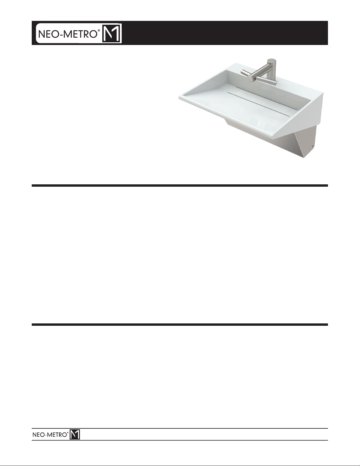
INSTALLATION, OPERATIONS
& MAINTENANCE MANUAL
Please visit for most current specifications.www.neo-metro.com
Date: 06/10/19
Part #: 6216-019-000