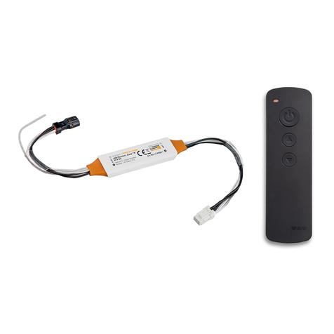
Ness 100-187 Quick start guide

INSTALLATION NOTES
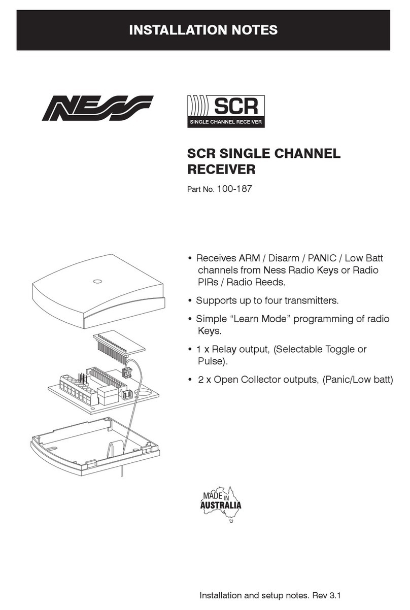
PART NUMBER: 100-187
MODEL: SCR Single Channel Receiver
NESS SECURITY PRODUCTS
RADIO COMMUNICATIONS COMPLIANCE
Australian Communications Authority
NESS SCR SINGLE CHANNEL RECEIVER

2
The Ness Standalone Wireless Receiver is a
unique high performance 303.875Mhz radio
receiver designed to operate in conjunction with
any Ness proprietary Radio Transmitting device
including Ness 3 Button Radio Pendants, Wrist
watch panic buttons, Radio Reed switches and
Radio PIR.
The Standalone Receiver is ideal for connecting
to Alarm panels which do not provide a wireless
facility and can be used for connecting, Wireless
devices for zone alarms, Panic buttons or Radio
Keys for Arming and Disarming the Panel. The
Control input on the Standalone Receiver gives it
the unique ability to identify the Armed/Disarmed
status of an Alarm panel and when used with a 3
button Pendant it allows the Receiver to always
correctly Arm or Disarm the Panel, unlike similar
receivers with a single button and toggling output
which can place the Panel in the wrong state
without the user realising the error.
The Standalone Receiver is also ideally suited for
applications which require a Remotely switched
Relay output for power switching applications e.g.
Garage door opening.
The Standalone Receiver comes complete with
separate Arm/Disarmed or Alarm Dry contact
Relay output, Panic output and Low battery
output . The Relay output can be selected to be
Pulsing or Latched to suit your application.The
Standalone Receiver will accept up to four
individual Radio Keys and Panic Buttons or up to
four alarm transmitting devices (Reed switches
or PIRs).
The Ness Standalone Receiver can be
programmed with up to four similar Ness
transmitting devices i.e. either Radio Key devices
(Panic buttons, On/Off keys) or Alarm transmitting
devices i.e. Reed Switches or Radio PIR's.
Note - You cannot mix Alarm devices with Key
type devices, the receiver will only accept one
type.
The Standalone Receiver will learn the Radio code
of the device to be programmed and the code will
be stored in non-volatile memory. The Standalone
Receiver will also allow the code to be overwritten
if required or erased totally, this is fully described
later in this manual.
1. Select a Radio device to be programmed into
the Standalone Receiver and place a link on the
Code number you wish it to be allocated to (Code
1 to Code 4 Links M1 to M2) .
The LED will change from a slow flash to either;
a) A faster flash indicating that the Code slot is not
yet programmed with any device. or,
b) Turn on steady indicating that there is already
a device programmed into that slot.
2. Make the device to be programmed into the
Standalone Receiver transmit 3 times, to achieve
this do the following;
- For a Radio Key Press the "OFF" Button 3
times.
- For a RK1 Radio Pendant press the Panic button
3 times ( be aware of the 1.5 second delay on the
button press).
- For a PIR you will need to place the PIR in Test
Mode and triger an alarm 3 times.
- For a Reed Switch you will need to trigger an
Alarm by moving the magnet away from the
Reed Switch then a Restore Alarm by moving
the Magnet back and finally another Alarm by
moving the magnet away.
INTRODUCTION PROGRAMMING
PROGRAMMING STEPS

3
If you wish to clear an already programmed
Device carry out the following steps, otherwise
if you simply wish to over-write a device with a
new one then carry out the steps described in
Programming Steps above.
1. Place the Program Link onto the number of the
Device you wish to clear (Code 1 to code 4)
2. The LED should be on steady indicating that
the slot has a device programmed into it.
3. Using any standard Ness Radio Key press the
"ON" Button once.
4. The LED should change from being on steady
to a fast flash indicating that the device has been
erased and that the slot is now clear.
5. Remove the Program link and park it on a single
pin for future use.
TO ERASE A CODE
3. You should notice that the LED will do the
following;
- Turn off on the first code received.
- Blink once quickly on the second code
received.
- Turn on steady on the third code received
indicating the code has been accepted and
programmed into memory.
4. To program more devices repeat steps 1 to 3
otherwise remove the program link and park it on
a single Pin for future use.
5. Once the Program Link is removed the
LED should flash slowly indicating normal
operation.
NOTE - Code 1 will always come factory
programmed with a Radio Key for test purposes
only.
INPUT - The input serves as an inhibit for the
Relay output depending on the state of the input.
Applying less than 1 Volt to this input makes it
"LOW" and applying greater than 4 Volts or leaving
this input open makes this input "HIGH". The
inhibit feature is only functional when Momentary
action is selected, this is more fully described
below.
For a summary of the action of this feature see
the table on the next page.
LATCH/MOMENTARY LINK LK1- The Relay
can be selected to either Toggle on Key button
presses or Pulse for 2 seconds when a valid code
is received.
Link On = Latching operation
Link Off = Momentary operation
OPTIONS
Link set to LATCH. (Only use with Radio Keys and
reed switches ). Inhibit Input has no effect.
Application 1. Relay Turns On and Off using
a Radio Key.
Pressing the "ON" button on a Ness Radio Key
will turn the Relay on. Further presses of the "ON"
button when the relay is on will have no affect.
Pressing the "OFF" button on Ness Radio Key will
turn the Relay off. Further presses of the "OFF"
button when the Relay is off will have no affect.
Application 2. Relay follows the state of the
Reed Switch.
When a single Reed switch alarms the Relay will
turn ON. When the Reed Switch restores the Relay
will turn OFF.
If more than one Reed switch is programmed
then the Relay will turn ON when any Reed
Switch alarms but will only turn OFF when all
Reed Switches have restored
OPTIONS - LATCHING

4
Link set to Momentary ( Can be used with Radio
Keys or Alarm Devices)
Application 1. PIRs and Reed Switch used in
normal alarm operation.
Use this application if you simply wish to add
alarm device to your control panel.
For Alarm Devices with the Inhibit input "High"
or left open.
The Relay will pulse on for 2 seconds every
time a valid code is received from any of the
programmed devices (PIR or Reed Switch)
when they Alarm.
Application 2. PIRs and Reed Switches Alarm
operation with Inhibit.
Use this special application if you need to inhibit
the alarm relay at certain times
For Alarm Devices with the Inhibit input switching
between "High" and "Low" (less than 1 Volt)
Whilst the Input is "High" the Relay will pulse on
for 2 seconds every time a valid code is received
from any of the programmed devices (PIR or Reed
Switches) when they alarm.
When the Input is changed to "Low" then all
Alarms will be ignored from the programmed
devices.
Only use this feature if you specifically wish to
ignore alarms from devices.
Application 3. Radio Key Simple Pulsing Relay
output.
Use this application if you want a simple pulsing
output with a Radio Key. Only the "ON" button on
the Radio Key will pulse the Relay.
For Radio Keys with the Inhibit input "High" or
left open.
Every time the "ON" button is pressed on the
Radio Key the Relay will pulse, pressing the
"OFF" button whilst the Inhibit is "High" will not
pulse the relay.
OPTIONS - MOMENTARY Application 4. Control Panel Arming using an
Armed/Disarmed output from the Panel.
Use this application for correctly Arming and
Disarming a Control Panel using the ON and
OFF buttons on a Radio Key as long as there
is an Armed/Disarmed Output from the Control
panel which can be wired into the Inhibit Input
on the Standalone Receiver.
When the Panel is Armed the Inhibit Input will
require a "LOW" or less than 1 Volt and when the
Panel is Disarmed the Inhibit Input will require
a "HIGH" or greater than 4 Volts. When wired
correctly the Relay output will do the following;
With the Panel Disarmed (Inhibit Input "High")
pressing the "OFF" button will have no effect,
pressing the "ON" button will pulse the Relay
output which can be used to Arm the Control
Panel.
With the Control Panel Armed ( Inhibit Input
"Low) pressing the "ON" button will have no effect,
pressing the "OFF" button will pulse the Relay
which can be used to Disarm the Control Panel.

5
ACTION LINK INPUT RELAY
3 button Key or Reed Switch Latching Input Ignored Toggle
Device Alarm, PIR or Reed Momentary Low < 1V No Change
Device Alarm, PIR or Reed Momentary High > 4V Pulse
Key “ON” Momentary Low < 1V No Change
Key “ON” Momentary High > 4V Pulse
Key “OFF” Momentary Low < 1V Pulse
Key “ OFF” Momentary High > 4V No Change
TABLE - OUTPUT OPERATION
RELAY - The relay output is a single pole
changeover dry contact rated at 1amp @ 28
Volts. The Relay output is used to provide either
Alarm output or Arm/Disarm output. The function
is more fully described above.
PANIC/TAMPER - The Panic/Tamper output is
an open collector (switched low) output rated at
20 mA. The Panic/Tamper output will pulse for 2
seconds every time that either;
a) A panic Button is pressed on a 3 Button Radio
Key or a Wrist watch button is activated or,
b) A Tamper Alarm is generated on a Radio PIR
or a Reed Switch.
Note - The Momentary/Latch Link has no affect on
the operation of the Panic/Tamper output.
LOW BATTERY - The Low Battery output is an
open collector (switched low) output rated at
20mA. The Low Battery output will pulse for 2
seconds every time that it receives a Low battery
signal from either a Radio Key or an Alarm
Device and should only be used as a warning
that batteries require changing.
Note - The Standalone receiver provides no
means of identifying which Key or Device has
caused the Low Battery alarm however all Ness
Keys and Alarm Devices display Low Battery by
flashing their LED instead of turning it on steady
when they are transmitting.
OUTPUTS
The Standalone receiver requires a DC regulated
supply from 10 - 14 Volts to operate correctly.
When operating normally the LED on the
Standalone Receiver will flash slowly. Whenever
a valid Radio transmission is received the LED
will Turn on for 2 seconds. Always ensure that
the Receiver is kept well away from potential
interference devices i.e. Televisions, Video's,
Computers, if you are experiencing problems
move the Receiver well away from other devices
then connect with a battery only and re-test to
attempt to isolate the cause of the problem.
Always keep the antenna J1 well away from your
control panel and wiring and potential Radio
Interference devices. The antennae should be
kept straight and not coiled up tightly or tied
into a knot. NEVER SHORTEN OR LENGTHEN
THE ANTENNA AS IT IS A CRITICALLY TUNED
LENGTH.
For details on the connection of external
antenna contact your nearest Ness Security
Sales Branch.
NORMAL OPERATION

6
TAMP
+12V
0V
Z8
C
Z7
Z6
C
Z5
Z4
C
Z2
Z3
C
Z1
0V
+12V
INPUT
0V
PANI C
TAMP
LOW
BATT
NO
NC
C
2K2
2K2
100-187
NESS SCR RECEIVER
LK1
J7
PROG
AREA1
WIRING SCR TO L8 PANEL
NESS SECURITY PRODUCTS
J7
AREA 1
AREA 2
Al 1
Al 2
Tamp
Excl
Batt
Main
+12V
0V
DAT
SON
KEY
+12
0V
Z1
Z3
Z5
Z7
C
C
C
C
Z2
Z4
Z6
Z8
+12
0V
TAMP
TAMPER SW
C
EARTH
+12V
INPUT
0V
PAN I C
TAMP
LOW
BATT
NO
NC
C
2K2
2K2
100-187
NESS SCR RECEIVER
C
Z6
WIRING SCR TO PRO-LD PANEL
NESS L8 MAIN BOARD
NESS PRO-LD MAIN BOARD

7
WIRING SCR TO PRO-LX PANEL
NESS SECURITY PRODUCTS
0V
+12V
AUX
RES
AC
NC
+12V COM
AC
C
LATCH
BAT+
EARTH
EARTH
NO
SIREN A
+12V COM
SIREN B
BAT -
Z1
Z3
Z5
Z7
C
C
C
C
Z2
Z4
Z6
Z8
+12
+12
+12
+12
GND
GND
0V
0V
TAMP
COM
KEY
COM
TAMPER SW
D IN
D IN
CLK
CLK
HEATSINK
+12V
INPUT
0V
PANIC
TAMP
LOW
BATT
NO
NC
C
2K2
2K2
100-187
NESS SCR
RECEIVER
NESS PRO-LX MAIN BOARD

8
NESS SCR RECEIVER
INSTALLATION NOTES
Document part number: 890-129
For products: 100-187 Ness SCR Receiver
© 2003 Ness Security Products Pty Ltd ABN 28 069 984 372
Specifications may change without notice.
Dimensions....................78(h) x 73(w) x 27(d) mm.
Operating voltage ...........10–15V DC
Standby current draw ....15mA
Radio frequency.............303.85MHz
Low Voltage Output........20mA @ 12V
Panic/Tamper Output......20mA @ 12V
Relay Output ..................Dry contact rated 1A @ 28V
Max. radio devices .........4
SPECIFICATIONS
NESS SECURITY PRODUCTS
RADIO COMMUNICATIONS COMPLIANCE
Australian Communications Authority
Table of contents
Other Ness Receiver manuals
