Neteon Parani-SD1100 User manual

Parani-SD1100
User Guide
Version 1.1.2.1
2015-09-10

2
User Guide for the Parani-SD1100
Version 1.1.2.1
Firmware version 1.1.X
Printed in Korea
Copyright
Copyright 2010~2015, Sena Technologies, Inc. All rights reserved.
Sena Technologies reserves the right to make changes and improvements to its product without
providing notice.
Trademark
Parani™ is a trademark of Sena Technologies, Inc.
Windows® is a registered trademark of Microsoft Corporation.
Ethernet® is a registered trademark of XEROX Corporation.
Notice to Users
When a system failure may cause serious consequences, protecting life and property against such
consequences with a backup system or safety device is essential. The user agrees that protection
against consequences resulting from system failure is the user's responsibility.
This device is not approved for life-support or medical systems.
Changes or modifications to this device not explicitly approved by Sena Technologies will void the user's
authority to operate this device.
Precautions and Safety
Electricity
Use only the supplied AC adapter. Use of unauthorized power adapter is not recommended. Electrical
shock may result.
Do not kink or crease the power cable or place heavy objects on the power cable. Fire can result from
damaged power cables.
Do not handle power plug and adapter with wet hands. Electrical shock may result.
Immediately power off the product and unplug the AC adapter if smoke or odors emit from the product
and adapter. Fire can result from improper use.
Immediately power off the product and unplug the AC adapter if water or other liquids are present. Fire
can result from improper use.
Product
Parani-SD1100 meets the RS-422/485 standards. Do not wire with non-standard products. Damage to
your products may result from improper use.
Do not drop or subject the device to impact. Damage to your products may result from improper use.
Keep away from harsh environments including humid, dusty, and smoky areas. Damage to your
products may result from improper use.
Do not use excessive force on the buttons or attempt to disassemble the device. Damage to your
products may result from improper use.
Do not place heavy objects on the product. Damage to your products may result from improper use.
Technical Support
Sena Technologies, Inc.
Tel: (+82-2) 576-7362
Fax: (+82-2) 573-7710
E-Mail: support@senaindustrial.com
Website: http://www.senaindustrial.com

3
Revision History
Revision
Date
Name
Description
V1.0.0
2010-07-20
Yh Moon
Initial Writing
V1.0.1
2011-03-10
JH Park
Modify S-Register 24.
Add Remote Configuration.
V1.0.2
2011-10-12
JH PARK
Modify invalid contents of serial port connection
V1.1.0
2011-12-26
HR Zo
Package does not contain CD-ROM
V1.1.1
2013-07-16
TM Kim
Version Update and Modify AT+MULTI
command of response
V1.1.2
2014-12-15
KY Kim
Modify Operating Temperature
V1.1.2.1
2015-09-10
TM Kim
Change the website address

4
Contents
1. Introduction 7
1.1. Overview ....................................................................................................................................7
1.2. Package Check List ...................................................................................................................7
1.2.1. Single Unit Package.........................................................................................................7
1.2.2. Bulk-Pack Package..........................................................................................................7
1.3. Product Specification .................................................................................................................8
2. Getting Started 10
2.1. Panel Layout ............................................................................................................................10
2.2. Connecting the Hardware ........................................................................................................11
2.2.1. Connecting Power to Parani-SD1100............................................................................11
2.2.2. Connecting Device to Parani-SD1100...........................................................................11
3. Configuration 12
3.1. Operation Modes......................................................................................................................12
3.2. LED Indicators..........................................................................................................................13
3.3. Serial Ports...............................................................................................................................13
3.4. Data Bit.....................................................................................................................................13
3.5. Reset to Factory Defaults.........................................................................................................13
3.6. Dipswitch..................................................................................................................................14
3.7. Pairing Button...........................................................................................................................14
3.8. Remote Configuration ..............................................................................................................16
3.9. Software and Utility ..................................................................................................................16
3.10. ParaniWIN..............................................................................................................................16
3.11. Parani Multi Wizard ................................................................................................................22
3.12. ParaniUpdater........................................................................................................................24
3.13. Terminal Program...................................................................................................................25
4. Multiple Connection Mode 27
4.1. Overview ..................................................................................................................................27
4.2. Configuration............................................................................................................................28
4.3. AT Commands..........................................................................................................................29
4.3.1. AT+MULTI,n...................................................................................................................29
4.3.2. AT+MLIST?....................................................................................................................29
4.3.3. ATHx, ATHbdaddr..........................................................................................................29
4.3.4. ATOx, ATObdaddr .........................................................................................................29
4.4. Notes........................................................................................................................................30
5. Approval Information 31
5.1. FCC..........................................................................................................................................31
5.1.1. FCC Compliance Statement..........................................................................................31
5.1.2. RF Exposure Statement.................................................................................................31
5.1.3. Do not.............................................................................................................................31
5.2. CE ............................................................................................................................................31
5.3. KCC..........................................................................................................................................31
5.4. TELEC......................................................................................................................................31
5.5. SIG ...........................................................................................................................................31
6. RF Information 32
6.1. Radio Frequency Range ..........................................................................................................32
6.2. Number of Frequency Channel................................................................................................32
6.3. Transmission Method...............................................................................................................32
6.4. Modulation Method...................................................................................................................32
6.5. Radio Output Power.................................................................................................................32
6.6. Receiving Sensitivity ................................................................................................................32
6.7. Power Supply...........................................................................................................................32
Appendix A: Connections 33
A.1. Serial Port Pin Outs .................................................................................................................33

5
A.2. RS422/485 Serial Wiring Diagram...........................................................................................34
Appendix B: AT Commands 35
B.1. Terminology..............................................................................................................................35
B.1.1. AT Command.................................................................................................................35
B.1.2. AT Response .................................................................................................................35
B.1.3. Operation Mode.............................................................................................................35
B.1.4. Operation Status............................................................................................................35
B.1.5. Security..........................................................................................................................35
B.1.6. Symbols.........................................................................................................................36
B.2. Command Category.................................................................................................................36
B.3. Command Description .............................................................................................................37
B.3.1. ATZ..............................................................................................................................37
B.3.2. AT&F............................................................................................................................37
B.3.3. AT.................................................................................................................................37
B.3.4. AT+UARTCONFIG,Baudrate,Parity,Stopbit.................................................................37
B.3.5. AT+USEDIP?...............................................................................................................37
B.3.6. AT+BTINFO?...............................................................................................................38
B.3.7. AT+BTINQ?..................................................................................................................38
B.3.8. AT+BTLAST?...............................................................................................................38
B.3.9. AT+BTVER?................................................................................................................38
B.3.10. AT+MLIST?................................................................................................................38
B.3.11. AT+BTMODE,n..........................................................................................................39
B.3.12. AT+MULTI,n...............................................................................................................39
B.3.13. +++.............................................................................................................................39
B.3.14. AT+SETESC,nn.........................................................................................................40
B.3.15. ATO(ATOx, ATObdaddr) ...........................................................................................40
B.3.16. AT+BTCANCEL.........................................................................................................40
B.3.17. AT+BTSCAN..............................................................................................................40
B.3.18. AT+BTSCAN,n,to.......................................................................................................40
B.3.19. AT+BTSCAN112233445566,to..................................................................................41
B.3.20. ATD............................................................................................................................41
B.3.21. ATD112233445566....................................................................................................41
B.3.22. ATH(ATHx, ATHbdaddr)............................................................................................42
B.3.23. AT+BTKEY=$string....................................................................................................42
B.3.24. AT+BTSD?................................................................................................................42
B.3.25. AT+BTCSD................................................................................................................42
B.3.26. AT+BTFP,n.................................................................................................................42
B.3.27. AT+BTSEC,Authentication,Encryption......................................................................43
B.3.28. AT+BTNAME=$string................................................................................................43
B.3.29. AT+BTLPM,n.............................................................................................................43
B.3.30. AT+BTRSSI,n(Single Connection Mode Only).........................................................43
B.3.31. AT+PASS=$string......................................................................................................44
B.3.32. AT+CHPASS=$string.................................................................................................44
B.3.33. AT&V..........................................................................................................................44
B.3.34. ATSnn?.....................................................................................................................44
B.3.35. ATSnn=mm................................................................................................................44
B.4. Command Validity....................................................................................................................45
Appendix C: S-Register 46
C.1. S1: Force to Reconnect (default 1)..........................................................................................46
C.2. S3: Stream UART Policy (default 0)........................................................................................46
C.3. S4: Enable Remote Name Query (default 1)...........................................................................46
C.4. S6: Enable Low Power Mode (default 0).................................................................................46
C.5. S10: Enable Response Message (default 1)...........................................................................46
C.6. S11: Enable Escape (default 1)...............................................................................................47
C.7. S12: Clear Data Buffer When Disconnected (default 1)..........................................................47
C.8. S22: Faster Connection (default 0)..........................................................................................47
C.9. S23: Intercharacter Timeout Setting (default 0).......................................................................47
C.10. S24: Maximum Number of Inquiry Result (default 15) ..........................................................47

6
C.11. S26: Intercharacter Timeout (default 0).................................................................................47
C.12. S28: Escape Sequence Character (default 43).....................................................................47
C.13. S31: Page Timeout (default 20).............................................................................................48
C.14. S33: Inquiry Timeout (default 30) ..........................................................................................48
C.15. S37: Supervision Timeout (default 5) ....................................................................................48
C.16. S43: COD (default 001F00)...................................................................................................48
C.17. S44: COD Filter (default 0)....................................................................................................48
C.18. S45: Inquiry Access Code (default 0x9E8B33) .....................................................................48
C.19. S46: BD Address of Last Connected Device.........................................................................48
C.20. S48: Low Power Max Interval (default 5000) ........................................................................48
C.21. S49: Low Power Min Interval (default 4500) .........................................................................48
C.22. S52: Low Power Timeout (default 5) .....................................................................................48
C.23. S54: BD Address of Last Connected Device.........................................................................49
C.24. S55: BD Address of Last Connected Device.........................................................................49
C.25. S56: BD Address of Last Connected Device.........................................................................49
C.26. S57: Slave Disconnect Timeout (default 3) ...........................................................................49
C.27. S58: MAX TX POWER (default 0).........................................................................................49
C.28. S59: Current Slave in Communication (default 0).................................................................49
C.29. S60: Reconnect Time Interval (default 5)..............................................................................49
Appendix D: Trouble Shooting 50
D.1. No Data Transmission .............................................................................................................50
D.1.1. COM Port Settings ........................................................................................................50
D.1.2. Pin Assignment..............................................................................................................50
D.2. Data Loss or Malfunctioning....................................................................................................50
D.2.1. Response Message.......................................................................................................50
D.3. Transmission Delay .................................................................................................................50
D.3.1. RF Processing Delay.....................................................................................................50
D.3.2. RF Transmission Environment......................................................................................50
Appendix E: Parani-SD1100 mechanical drawing 51
E.1. Parani-SD1100 mechanical drawing (mm)..............................................................................51
Appendix F: Warranty 52
F.1. GENERAL WARRANTY POLICY.............................................................................................52
F.2. LIMITATION OF LIABILITY ......................................................................................................52
F.3. HARDWARE PRODUCT WARRANTY DETAILS ....................................................................52
F.4. SOFTWARE PRODUCT WARRANTY DETAILS.....................................................................53
F.5. THIRD-PARTY SOFTWARE PRODUCT WARRANTY DETAILS............................................53

7
1. Introduction
1.1. Overview
Parani-SD1100 is a terminal device for wireless serial communication using Bluetooth 2.0+EDR
technology that is an international standard of short range wireless communications. Parani-SD1100
can communicate with other Bluetooth devices; user may connect other Bluetooth devices that support
the Serial Port Profile.
The working distance of Parani-SD1100 with default antenna is 100m
Parani-SD1100 has a compact design, which allows it to be placed conveniently into various devices or
equipment. Its detachable antenna has the ability to optimize the quality and distance of wireless
communications.
Parani-SD1100 supports FHSS (Frequency Hopping Spread Spectrum), which is a technique, native to
Bluetooth that allows the Parani-SD1100 minimize radio interference while decreasing the likelihood of
over-air hijacking. Parani-SD1100 also supports authentication and Bluetooth data encryption.
Parani-SD1100 can be configured and controlled by a set of AT commands. Users can easily configure
Parani-SD1100 on a terminal program, such as HyperTerminal, and configure for wireless
communication without modifying user’s existing serial communication program. User friendly
ParaniWIN can also be used for easy setup on Microsoft Windows.
1.2. Package Check List
1.2.1. Single Unit Package
SD1100-A1 (Stub antenna NOT included)
- Parani-SD1100
SD1100-00
- Parani-SD1100
- Stub Antenna
- DC Power Cable
- USB Power Cable
- DB9-Terminal Block
SD1100-01
- Parani-SD1100
- Stub Antenna
- DC Power Cable
- USB Power Cable
- DC Power Adapter
- DB9-Terminal Block
1.2.2. Bulk-Pack Package
SD1100-B10
- Parani-SD1100 x 10 EA
- Stub Antenna x 10 EA
- DC Power Cable x 10EA

8
1.3. Product Specification
Parani-SD1100
Serial Interface
One male DB9 serial port for data communication
Serial UART speed up to 921.6kbps
RS422 : TXD+, TXD-, RXD+, RXD-
RS485 - TRXD+. TRXD-
Bluetooth Interface
Bluetooth v2.0 + EDR
Profile: Serial Port Profile
Class 1
Working distance:
Stub Antenna - Stub Antenna 100 meters
Stub Antenna - Dipole Antenna 150 meters
Dipole Antenna - Dipole Antenna 200 meters
Dipole Antenna - Dipole Antenna 300 meters
Dipole Antenna - Patch Antenna 500 meters
Dipole Antenna - Dipole Antenna 400 meters
Dipole Antenna - Patch Antenna 600 meters
Patch Antenna - Patch Antenna 1,000 meters
Configuration
ParaniWIN, ParaniMultiWizard, Modem AT command set
Firmware Update
ParaniUpdater
Diagnostic LED
Power, Standby, Connect, Serial Rx/Tx
Power
Supply voltage: 5V ~ 12V DC
Power consumption: 80mA@5VD Max
Environmental
Operating temperature: -40 ~ 85 oC
Storage temperature: -40 ~ 85 oC
Humidity : 90% (Non-condensing)
* The performance may drop in high or low temperatures.
Physical properties
- Dimension (L x W x H)
74 x 31 x 16 (mm)
- Weight: 24g
Approvals
FCC, CE, TELEC, KCC, SIG

9
Warranty
3-year limited warranty
Note *:
Bluetooth v2.0 supports improved AFH function. AFH function is to mitigate the interference
between WiFi and Bluetooth radios by automatically avoiding the active WiFi channel from
Bluetooth link. However, AFH does not provide a complete solution making WiFi and Bluetooth
work together in harmony. It is highly recommended for users to test their wireless system
enough before deployment since the overall system performance is affected by various
environmental factors such as distance between them.
10
2. Getting Started
This chapter describes how to set up the Parani-SD1100 for the first time.
- 2.1 Panel Layout explains the panel layout.
- 2.2 connecting the Hardware describes how to connect the power, the serial device to the Parani-
SD1100.
Following items are required to get started:
- One DC power adapter, USB power cable or DC power cable (included in the package).
- RS232-422/485 Converter
Users may need to use specific type of adapter to fit for the RS232-422/485 converter he may have. If
users’ converter is DB9 female type to connect to SD1100, then he may not need additional adapter.
The following picture is an example of the adapter that is fir for RS232-422/485 Converter whose
connector for the SD1100 wiring has a terminal block interface. If the connector with same type has the
different location of the serial signals, it needs to be wired properly according to the serial signals.
* Users need to wire the serial signals matching the Pin outs of SD1100 to make RS422/485
communication possible. (Refer to A.1. Serial Port Pin Outs) User can also do it using the accessory
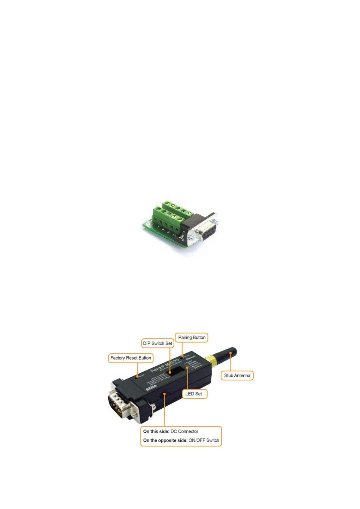
with DB9-Terminal Block type as below.
Figure 2-1 DB9-Terminal Block
- One PC with RS232 serial port.
- Terminal emulation program running on the PC.
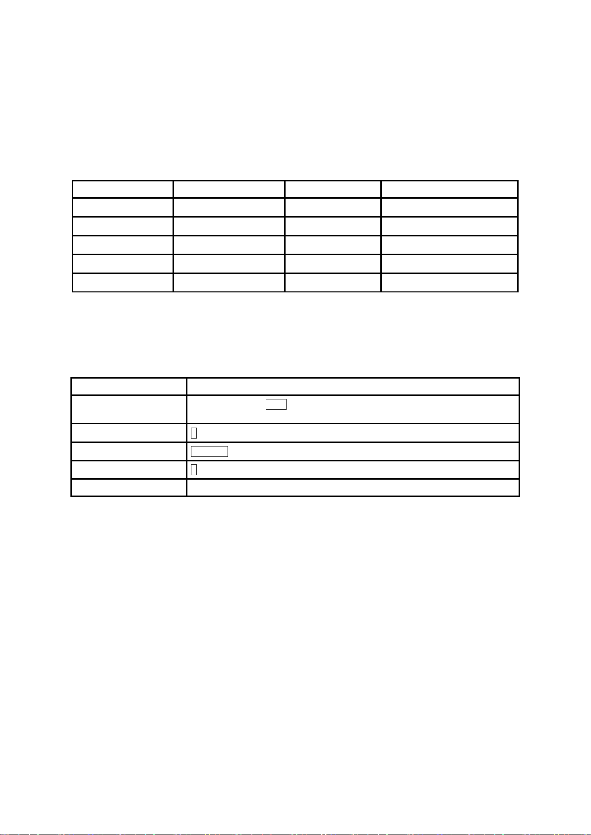
2.1. Panel Layout
This section describes the panel layout of the Parani-SD1100.
Figure 2-2 The panel layout of Parani-SD1100

11
2.2. Connecting the Hardware
This section describes how to connect the Parani-SD1100 to the serial device.
- Connect a power source to the Parani-SD1100.
- Connect the Parani-SD1100 to a serial device.
2.2.1. Connecting Power to Parani-SD1100
Parani-SD1100 can be powered from either external DC power adaptor/external power source. To power
the SD1100 from the external DC power adaptor or external power source, connect the power jack to
the power connector of the Parani-SD1100 using the DC power adapter, USB power cable or DC power
cable that is included in the package. If power is properly supplied, the [Power] lamp will display a green
color.
Figure 2-3 Connecting Power to Parani-SD1100
2.2.2. Connecting Device to Parani-SD1100
On connecting users’ serial device, users may wire it as to its interface and users may use wiring adapter.
Figure 2-4 Connecting a Serial Device to Parani-SD1100

12
3. Configuration
3.1. Operation Modes
In addition to the serial port configurations the Parani-SD1100 also requires some settings for Bluetooth.
For getting the most out of Parani-SD1100, user should understand the following Bluetooth connection
schemes.
A Bluetooth device can play a role as a master or slave. Master tries to connect itself to other Bluetooth
devices, and slave is waiting to be connected from other Bluetooth devices. A Bluetooth connection is
always made by a pair of master and slave devices. Aslave can be in two modes, Inquiry Scan or Page
Scan mode. Inquiry Scan mode is waiting for a packet of inquiry from other Bluetooth device and Page
Scan mode is waiting for a packet of connection from other Bluetooth device. Every Bluetooth device
has its unique address, called BD (Bluetooth Device) address, which is composed of 12 hexa-decimal
numbers.
Parani-SD1100 has 4 operation modes as follows. Each mode can be identified with LED indicators as
illustrated in next section.
Table 3-1 The Parani-SD1100 Operation Modes
Mode
Description
Mode0
In this mode, there is no response when power on or software reset, and Parani-SD1100 is
just waiting for AT command input. Neither master nor slave is assigned to Parani-SD1100 in
mode0. User can change the configuration parameters of Parani-SD1100 in this mode.
Parani-SD1100 must be in Mode0, when it is directly controlled by AT commands.
The factory default is set to Mode0.
Mode1
Parani-SD1100 tries to connect the last connected Bluetooth device.
Parani-SD1100 in Mode1 is to be a master and tries to connect the last connected Bluetooth
device. Parani-SD1100 always stores the BD address of the Bluetooth device to which Parani-
SD1100 has connected last. When Parani-SD1100 is initially used or after hardware reset,
there is no BD address stored in Parani-SD1100. In this case, Mode1 will not be able to work
properly. The mode change to Mode1 can be made after Parani-SD1100 succeeds to connect
to one other Bluetooth device. Once changed to Mode1, Parani-SD1100 will try to connect
automatically the last connected Bluetooth device whenever the unit is powered on or software
reset.
Parani-SD1100 in Mode1 cannot be discovered or connected by other Bluetooth devices.
Mode2
Parani-SD1100 is waits for a connection from the last connected Bluetooth device.
Parani-SD1100 in Mode2 is to be a slave and waiting for the connection only from the last
connected Bluetooth device. Just like Mode1, if there is no BD address stored in Parani-
SD1100, the mode change from other operation modes to Mode2 is not work properly. Once
changed to Mode2, Parani-SD1100 will wait for the connection from the last connected
Bluetooth device whenever the unit is powered on or software reset.
Parani-SD1100 in Mode2 cannot be connected to Bluetooth devices other than the last
connected device.
Mode3
Parani-SD1100 is waiting for the connection from any other Bluetooth devices. In Mode 3 the
Parani-SD1100 is discoverable and can be connected to by other Bluetooth devices.
13
3.2. LED Indicators
Serial-Tx and Serial-Rx LED will flash accordingly when data is transmitted. For small data
transmissions, it may be hard to recognize the quick flashing action of the LED.
Table 3-2The Parani-SD1100 LED Indicators
Indicator
Power LED
Standby LED
Connect LED
Mode0
Green┏━━━━━
Red┏━━━━━
Mode1
Green┏━━━━━
Green (every 1 sec) ┏┓
Mode2
Green┏━━━━━
Green (every 3 sec) ┏┰┓
Mode3
Green┏━━━━━
Green (every 3 sec) ┏┰┰┓
Connected
Green┏━━━━━
Green┏━━━━━
3.3. Serial Ports
The applicable settings for serial ports are as follows.
Table 3-3 The Parani-SD1100 Serial Port Settings
Serial Port Settings
Values
Baudrate
1200, 2400, 4800, 9600, 14400, 19200, 38400, 57600, 115200, 230400, 460800,
921600
Data bite
8
Parity
No parity, Even parity, Odd parity
Stop bit
1, 2
Hardware Flow Control
No Use
The values in box are the factory defaults. The flow control setting is configurable only through dip switch.
3.4. Data Bit
Parani-SD1100 supports only 8 data bit. In the case of 7 data bit and even/odd parity, use SD 8 data bit
and none parity. At this time, master and slave are Parani-SD, Parani-ESD or Parani-MSP series. But 7
data bit and none parity is not support.
3.5. Reset to Factory Defaults
To set all the configuration settings to its factory default parameters, press the reset button, depicted in
Fig. 3-1. Press and hold (for at least 1 sec) the reset button with a narrow pointed tool like paper clip.
Reset works only when power is on.

14
3.6. Dipswitch
With the combination of 4 slot dipswitches, RS422/485 select, Termination resistor on/off, RS485 echo
on/off and UART configuration can be set.
Figure 3-1 The Parani-SD1100 Dipswitch
Table 3-4 RS422/485 Select by Dipswitch
RS422 ↔RS485
422
485
Table 3-5 Termination Resistor Select by Dipswitch
Termination R Off ↔On
Off
On
Table 3-6 RS485 Echo Control by Dipswitch
RS485 Echo Off ↔On
Off
On
Table 3-7 UATR Configuration by Dipswitch
9600-8N1 ↔SW Config
9600-8N1
SW Config
* Note 1: You can set the Parani-SD1100 to of the default UART configuration of 9600-8N1 by way of
the Dipswitch. If you want to use other than the default UART configuration, please configure the
dipswitch to SW Config setting and use ParaniWIN or AT commands. Please refer to 3.9. ParaniWIN
and Appendix B.3.4. AT+UARTCONFIG, Baudrate,Paraty,Stopbit.
*Note 2: If you use 485 Echo option when you use both master and slave units as SD1100, then it may
cause data loss or conflict with various control messages such as AT response messages, i.e. OK,
ERROR, CONNECT, DISCONNECT. Please refer to Appendix C.5. S10: Enable Response Message
and turn off the corresponding option.
3.7. Pairing Button
Parani-SD1100 provides Pairing Button for instant configuration without a PC to make an automatic
connection between two Parani-SD1100s. In this example we will refer to the two Parani-SD1100s as
SD1 and SD2. (Only single connection mode)
Step 1. Turn on SD1 and SD2 and reset both of them by pressing Factory Reset Button.

15
Step 2. Press the Pairing Button of SD1 for 2 seconds until Connect LED blinks 3 times every 3 seconds.
Keep the power ON.
Step 3. Press the Pairing Button of SD2 for 2 seconds until Connect LED blinks 3 times every 3 seconds.
Now press again the Pairing Button for 2 seconds until Connect LED blinks every second.
Step 4. Wait for SD1 & SD2 to connect to each other until the Connect LED’s of SD1 and SD2 blink
every 1 second. It takes about 10 seconds to make a connection. If there are many Bluetooth devices
nearby, it may take longer.
Step 5. Turn SD1 off and on. Connect LED blinks twice in green every 3 seconds.
Step 6. Turn SD2 off and on. Connect LED blinks in green every second.
Step 7. Now SD1 and SD2 are configured to make automatic connection to each other, whenever they
are powered on.
Using a pair of Parani-SD1100 in this fashion is similar to that of using a wireless serial cable.
* Note: When using the pairing buttons, the Command Response option will be deactivated automatically.
The Parani-SD1100 will not send the response messages such as OK, ERROR, Connect and
Disconnect.
Table 3-8 Pairing Process by Pairing Button
SD1
Status
LED
SD2
Status
LED
1. Factory reset
Mode0
Standby LED turns on.
1. Factory reset
Mode0
Standby LED turns on.
2. Push pairing
button
Mode3
Connect LED blinks 3
times every 3 sec.
2. Push pairing
button
Mode3
Connect LED blinks 3
times every 3 sec.
3. Push pairing
button again
Mode1
Connect LED blinks
every second.
4. Connected
Slave
Connect LED is lit in
green
4. Connected
Master
Connect LED is lit in
green
Using pairing button, users can make a pairing connection between a Parani-SD unit and other
Bluetooth devices.
Step 1. Turn on SD1 and reset it by pressing Factory Reset Button.
Step 2. Press the Pairing Button of SD1 for 2 seconds until Connect LED blinks 3 times every 3 seconds.
Keep the power ON.
Step 3. Users can discover and connect to SD1 by using the software or user interface of other
Bluetooth device that they want to connect from.
Step 4. When they are connected, the Connect LED of SD1 blinks every 1 second.
Step 5. Turn off and on. Connect LED blinks twice in green every 3 seconds.
Step 6. Now SD1 is waiting for a connection from the last connected Bluetooth device. The last
connected Bluetooth device can connect to SD1.
Table 3-9 Pairing Process with other Bluetooth device by Pairing Button
SD1
Status
LED
Other Bluetooth Device
Status
1. Factory reset
Mode0
Standby LED turns on.
2. Push pairing button
Mode3
Connect LED blinks 3
times every 3 sec.
3. Inquiry and connect to SD1
4. Connected
Slave
Connect LED is lit in
green
4. Connected
Master

16
3.8. Remote Configuration
Parani-SD1100 supports remote configuration. After connecting to the Parani-SD1100 through Bluetooth,
before sending any other character, send three escape character (default :+). Then, the Parani-SD1100
will enter remote configuration mode and print “Please Enter Password”. You have to enter the password
with “AT+PASS” command within 2 minutes. After the password authentication, you are able to enter
any at command except “ATH”, “ATO”, “ATD”, “AT+BTSCAN”, “AT+BTINQ?” and “AT+BTCANCEL”. The
default password is “0000” and it is configurable with “AT+CHPASS” command.
Example of remote configuration:
Example of remote configuration mode.
3.9. Software and Utility
This configuration software and utility for firmware update is included with the product, which also can
be downloaded from http://www.senaindustrial.com.
Table 3-10 Configuration Software
Software
Purpose
Operating System
ParaniWIN
Configuration
MS Windows 98SE or Higher
ParaniMultiWizard
Multiple Connection Configuration
MS Windows 98SE or Higher
ParaniUpdater
Firmware Update
MS Windows 98SE or Higher
3.10. ParaniWIN
ParaniWIN is a program that runs on Microsoft Windows for the configuration of Parani-SD1100. Install
ParaniWIN on your computer. Plug a Parani-SD1100 into the serial port of the computer to use RS232
RS422/485 converter (SENA LTC 100) and turn on the power. Run ParaniWIN.
CONNECT 000195000001
+++
Please Enter Password
AT+PASS=0000
Remote Configuration Enabled
AT+BTINFO?
000195000001,SD1100v1.1.1-095515,MODE0,CONNECT,0,0,HWFC

17
Figure 3-2 Serial Port Setting
Set each option properly and click [OK], then the Main Window appears displaying the configuration of
SD1100. If the settings of the Parani-SD1100 are different from that of the ParaniWin, an error message
will pop up.
If the Parani-SD1100 is in the status of connection, warning message will pop up. Then the current
connection can be cancelled by [Disconnect] button on the main window.
Figure 3-3 Disconnect Window

18
Figure 3-4 Information Window
Serial port settings can be changed by <Start Configuration> and <ParaniWIN Configuration> of
ParaniWIN in the menu bar at upper left corner of the window without re-running the ParaniWIN program.
Figure 3-5 Menu Bar at Upper Left corner of ParaniWIN
When the ParaniWin software is able to access the Parani-SD1100 properly, the icons such as Device
Setting, Connection(out), Connection(in) and Connection Wizard in the left side window will become
available for use.
In Device Setting Window, hardware reset can be executed or operation mode and RS232 can be
configured as well. Security option also can be configured in this window.

19
Figure 3-6 Device Setting Window
Parani-SD1100 supports two security options, Authentication and Encryption. If you enable the
Authentication option, you must also enter a Pin Code value. If the authentication is enabled, the
connection, between the Master and Slave device must share the same Pin Code. In case that Parani-
SD1100 connects to another Bluetooth device, that requires authentication, you must know the other
device’s Pin Code. In general, most Bluetooth devices have a pincode of 1234 or 0000.
If you check Encryption option, the Parani-SD1100 will encrypt packets and sent to the device. The
Encryption options works well in case that only one of the devices between Master and Slave use the
Encryption option.
Parani-SD1100 has 4 response messages, ‘OK’, ‘ERROR’, ‘CONNECT’, and ‘DISCONNECT’. In some
cases, these responses can affect the host system unexpectedly. To prevent this, user can set the
Command response to ON or OFF.
If dipswitch for UARTConfiguration is put at 9600-8N1, Baudrate, Parity and Stopbit cannot be set. They
are configurable at SWConfig mode. The options which are not configurable are deactivated according
to the model of Parani series.
Click [Apply] button to apply any changes made to the Parani-SD1100.
Connection(out) icon will show the following window to search and connect other Bluetooth devices.

20
Figure 3-7 Connection (out) Window
Click [Search] button to search nearby Bluetooth devices. Once several Bluetooth devices has been
found, select one of the devices and click the [Connect] button. The selected Bluetooth device must be
discoverable and connectable. Click [Disconnect] button to close the connection.
After the connection has been established, you will be able to test signal strength by pushing the [START]
button.
Figure 3-8 Signal Strength Test
Table of contents


