NetPilot NetPilot Series User manual
NetPilot™Range
Getting Started Guide
NetPilot Internet Security Limited
November 2009

NetPilot Internet Security limited.All rights reserved. No part of this
documentation may be reproduced in any form or by any means or used to make
any derivative work (such as translation, transformation, or adaptation) without
permission from NetPilot Internet Security Limited.
NetPilot Internet Security Limited reserves the right to revise this documentation
and to make changes to its content from time to time without obligation on the
part of NetPilot Internet Security Limited to provide notification of such revision or
change.
NetPilot Internet Security Limited without warranty of any kind, either implied or
expressed, including, but not limited to, the implied warranties of merchantability
and fitness for a particular purpose. NetPilot Internet Security Limited may make
improvements or changes in this product(s) and/or the program(s) described in
this documentation at any time.
Unless otherwise indicated, NetPilot Internet Security Limited registered
trademarks are registered in the United Kingdom and may or may not be
registered in other countries. NetPilot Internet Security, NetPilot, IBX and
Boundary Caching are trademarks of NetPilot Internet Security Limited.
CompuServe is a registered trademark of CompuServe, inc. Novell, NetWare
and Yes NetWare are registered trademarks of Novell Inc. Windows, Windows
95, Windows 98, Windows 2000, Windows XP and the Windows logo are
registered trademarks of Microsoft Corporation. VT100 is a registered trademark
of Digital Equipment Corporation. Other brand and product names may be
registered trademarks or trademarks of their respective holders.
Under no circumstances will NetPilot Internet Security be deemed liable for any
Internet call connection costs whatsoever. It is solely the responsibility of the
installer and owner of any and all the devices to ensure correct installation and
correct on-going use.
Environmental Statement:
It is NetPilot Internet Security Limited’s policy to be environmentally friendly in all
its operations. This manual is printed on paper that comes from sustainable,
managed European forests. The production process for making the pulp has a
reduced AOX level (adsorbable organic halogen) resulting in elemental chlorine-
free paper.
This paper is fully biodegradable and recyclable.
NIS-NetPilot-GS-001

Contents
Getting Started – New NetPilot Range 1
Contents
Contents...............................................................................1
Using this Guide...................................................................3
Text Conventions in This Guide............................................................3
Support..................................................................................................4
Product Pack contents ........................................................5
Choosing a location for installation ....................................7
Installation Requirements......................................................................7
Rack installation....................................................................................8
Connecting the Power Cable..............................................................10
Getting to know NetPilot ...................................................11
Power Switch ......................................................................................11
Front and Rear panels - NetPilot Guardsman ...................................12
Front and Rear panel NetPilot Vanguard - Desktop...........................13
Front and Rear panel NetPilot Vanguard – Rackmount .....................14
Front and Rear panel NetPilot Globemaster.......................................14
Front and Rear panel NetPilot Globemaster.......................................15
Installation.........................................................................17
Power connection................................................................................17
LAN connection...................................................................................17
Connecting to a hub or switch.........................................................17
Connecting to a single PC...............................................................17
Internet connection..............................................................................18
Connecting via an Ethernet cable/ADSL.........................................18
Powering on........................................................................................19
Powering off........................................................................................19
Configuring the NetPilot unit.............................................20
NetPilot Connection Configuration......................................................20
Manual configuration of LAN2 for Internet access..........................21
Technical Information........................................................22
Interface Specifications.......................................................................22

Contents
Getting Started – New NetPilot Range 2
Physical Specifications........................................................................23
European Approvals...........................................................24
EMC Directive Compliance.................................................................24
CE Certification...................................................................................24
General Safety Information ...............................................25
Important Safety Information ............................................27
Importante notice de Sécurité.............................................................28
Wichtige Sicherheitshinweise .............................................................29
Informazioni di Sicurezza importanti...................................................30
Información de Seguridad importante.................................................31
Additional Safety Information..............................................................32
Using this Guide
Getting Started – New NetPilot Range 3
Using this Guide
Throughout this guide, blocks of text may be accompanied by an icon
and printed in bold or italic type. These blocks are Warnings, Cautions
and Notes and are used as follows:
WARNINGS and CAUTIONS: contain directions that
you must follow for your personal safety. Follow all
instructions carefully.
NOTES: These comments are to advise you of
important information that helps you make better use
of your product.
Text Conventions in This Guide
The examples below identify and explain specially formatted text that is
used throughout this guide.
Key names appear in a boldfaced type, very much the way they
appear on the keyboard; for example, Home, End, Backspace,
Tab.
When keys must be pressed at the same time, the action is
represented by the key names and the plus (+) symbol; for
example, Ctrl+Alt+Delete.
Drive letters that are not in command lines are presented in
uppercase type as shown here: drive A.
Software directory names or folders that are not in command
lines are presented in uppercase type as shown here:
DIRECTORY.
The file names are presented in uppercase italic type as shown
here: FILENAME.
The names of commands are presented in lowercase, bold italic
type as shown here: install, or a:\install. Commands that are to
be entered at the system prompt may be shown on a separate
line.

Using this Guide
Getting Started – New NetPilot Range 4
The names of items on the desktop are presented in a boldfaced
type. For example, you are directed to "double-click on the My
Computer icon on the desktop". The names of software
programs and items on the menu bar are also presented in a
boldfaced type. For example, you are directed to "choose Start,
then Programs, then Internet Explorer from the menu bar".
When you need to type information without pressing the Enter
key, you are directed to "type" the information.
When you need to type information and press the Enter key, you
are directed to "enter" the information.
Support
Technical support issues are covered in greater depth in our ‘How to’
documents available in our Support section on www.NetPilot.com,
which we update regularly.
The latest version of software can also be downloaded directly from our
website to a PC on your network then transferred to the NetPilot. We
recommend that you check this site for the latest upgrades.
To enable you to download upgrades, you must have first registered your
unit, and this can also be done on the same web site.
NB: For first line telephone support, please contact your NetPilot
supplier.

Pack Contents
Getting Started – New NetPilot Range 5
Product Pack contents
Before installing the NetPilot please check the pack contents. Your
NetPilot pack should contain depending on model type:
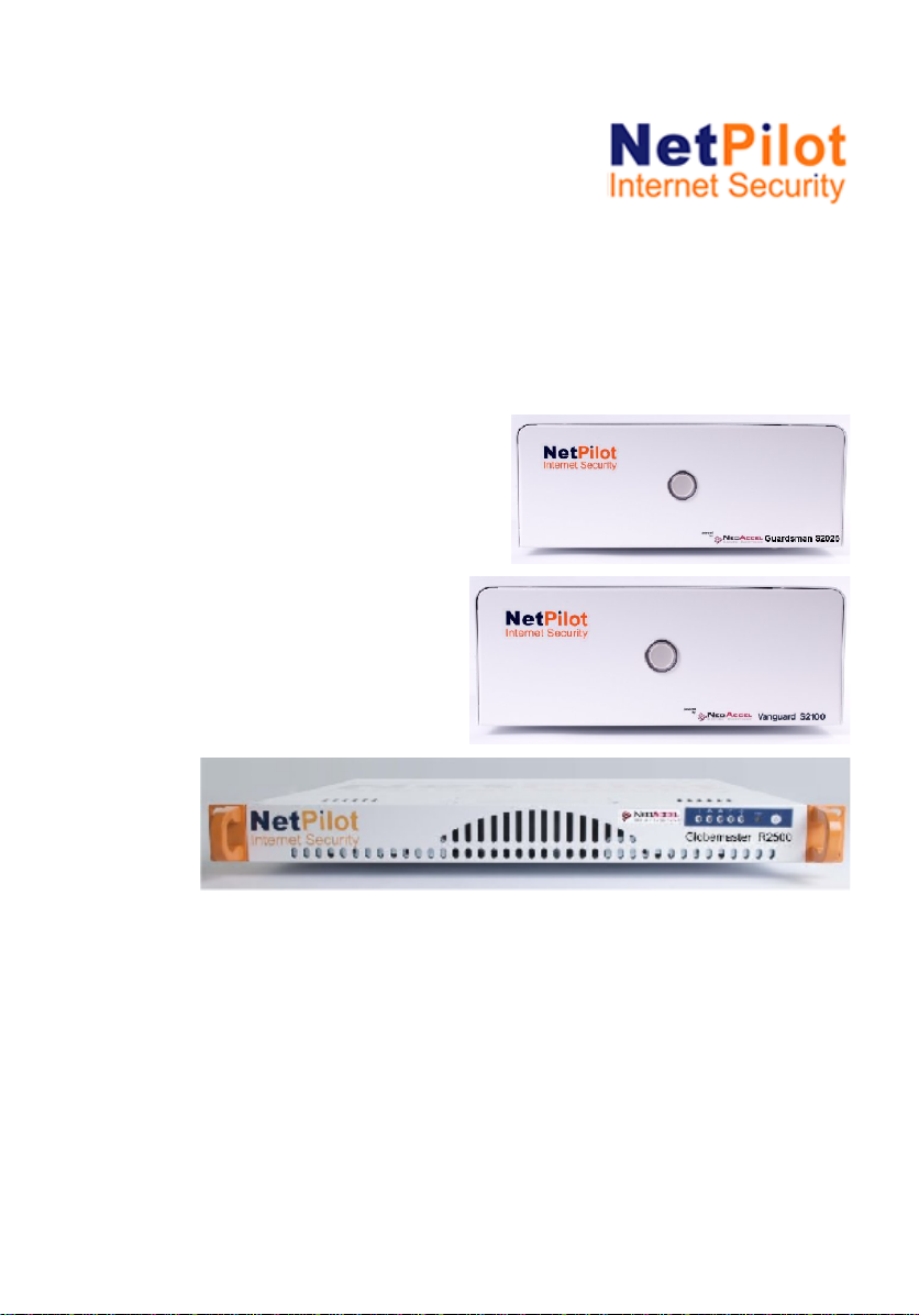
NetPilot Guardsman with Dual Ethernet interfaces
NetPilot Guardsman unit.
Power cable with appropriate plug for the national power supply.
Cable pack.
NetPilot Getting Started Sheet.
NetPilot Vanguard with Triple Ethernet interfaces
NetPilot Vanguard unit.
Power cable with appropriate plug for the national power supply.
Cable pack.
NetPilot Getting Started Sheet.
NetPilot Globemaster (rack mountable or tower unit) with Triple
Ethernet interfaces
NetPilot Globemaster 19” rack mountable unit with rack fixing pack
or tower unit
Cable pack with appropriate plug for the national power supply.
Cable pack.
NetPilot Getting Started Sheet.
If any of the items have been damaged in transit or are missing,
contact the NetPilot Internet Security Limited reseller from whom the
equipment was purchased.
Installation
Getting Started – New NetPilot Range 6
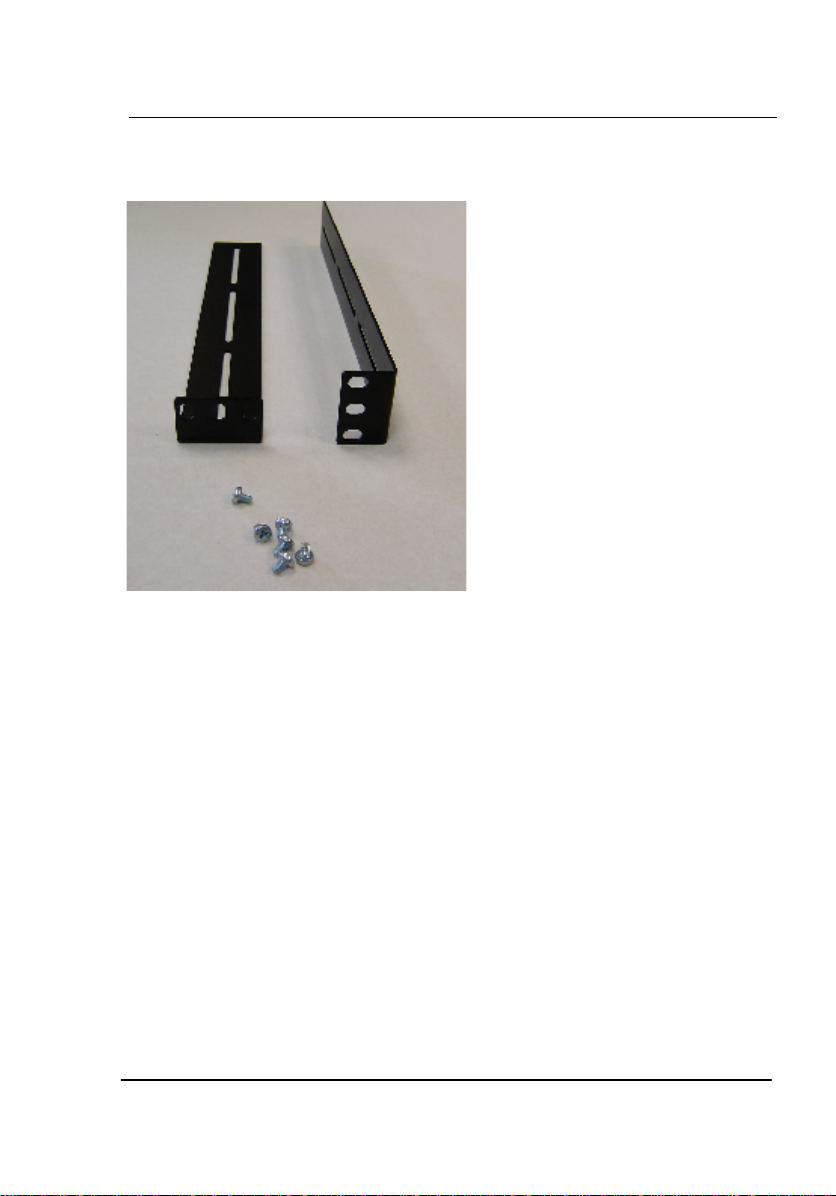
Picture below shows rack fixing pack

Installation
Getting Started – New NetPilot Range 7
Choosing a location for installation
When installing your NetPilot ensure:
It is accessible and cables can be easily connected.
Ensure the unit is placed on a cool surface.
It is out of direct sunlight and away from sources of heat.
Cabling is away from power lines, fluorescent lighting fixtures
and sources of electrical noise such as radios, transmitters and
broadband amplifiers.
Water or moisture should not enter the case of the unit.
Airflow around the unit and through the vents in the side of the
case is not restricted. We recommend that you provide a
minimum of 25 mm (1 inch) clearance around the unit.
Do not rest objects directly on top of the unit.
Installation Requirements
The following items are needed in order to install the NetPilot:
A suitable cable for connection to the LAN or workstation (if only
a workstation is attached to the unit).
For connecting to a remote site over an ADSL modem or a
leased line, a suitable Internet cable is required.
Installation
Getting Started – New NetPilot Range 8
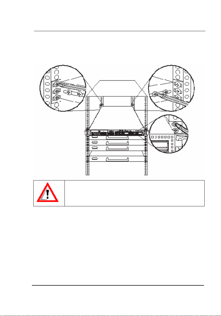
Rack installation
The NetPilot Globemaster can be mounted in a rack using the supplied
rack mounting kit which contains:
Mounting Brackets x 2
Screws x 6
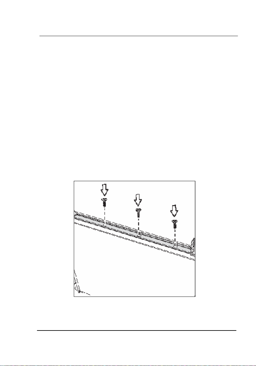
Follow these instructions to mount the unit into an industry standard 19"
rack:
The NetPilot Globemaster is shipped with a set of brackets for
mounting in a 19” Rack system. Along the Enterprise unit
openings are provided to which the brackets can be fasten.
Slide the brackets along the unit until they are in a suitable
position and then screw in three of the supplied screws on each
side.
Installation
Getting Started – New NetPilot Range 9
Lift the unit into place in the rack and screw it into place as
shown.
To avoid injury, it is strongly recommended that one person lift
the NetPilot Globemaster in place while a other person screws
it to the rack.

Installation
Getting Started – New NetPilot Range 10
Connecting the Power Cable
First, read the chapter “General Safety Information”.
Do not have any power supply connected to the unit
until you have installed the unit into its final location.
Ensure any on/off power switches at the outlet socket
are set to their ‘OFF’ positions.
The following steps are necessary to connect the device with mains:
oConnect the power lead to the power connector on the rear
panel of the NetPilot.
oPlug the mains plug of the power lead into a standard mains
wall socket, but DO NOT switch it on yet.
oNetPilot needs to be connected to your local area network
(LAN) as well as the Internet via a suitable wide area
network (WAN) connection.

Installation
Getting Started – New NetPilot Range 11
Getting to know NetPilot
Power Switch
It is advisable to shut down the system under software control to
guarantee that any open files on the system disk are closed correctly. In
order to power down the NetPilot in the recommended manner, the
power switch on the front panel provides a signal to the main processor
to begin the shutdown procedure. This process is indicated by beeps
which will indicate the start and end of the shutdown. After a period, the
front panel indicator LEDs will go out, the fans will stop and the power
lead may be removed from the NetPilot. If the power lead is removed
without using the power switch or there is a mains power failure, the
NetPilot may have to rebuild any of the files that were open which will
result in the next power-up taking more time.
Installation
Getting Started – New NetPilot Range 12
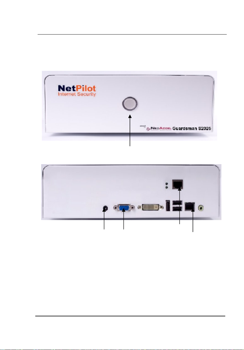
Front and Rear panels - NetPilot Guardsman
Monitor
LAN2
LAN1
Power Switch
Power Inlet
Installation
Getting Started – New NetPilot Range 13
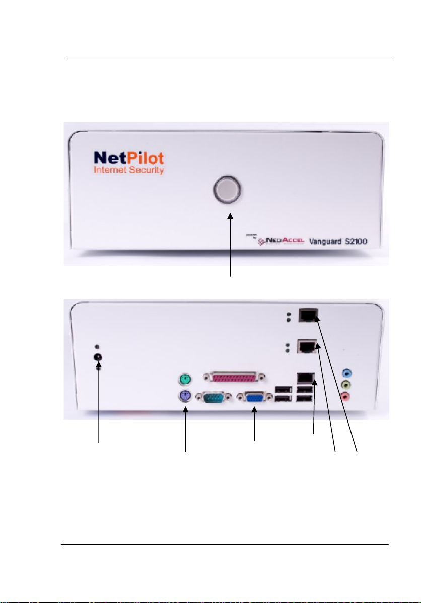
Front and Rear panel NetPilot Vanguard - Desktop
Keyboard
Monitor
LAN3
LAN2
Power Switch
Power Inlet
LAN1
Installation
Getting Started – New NetPilot Range 14
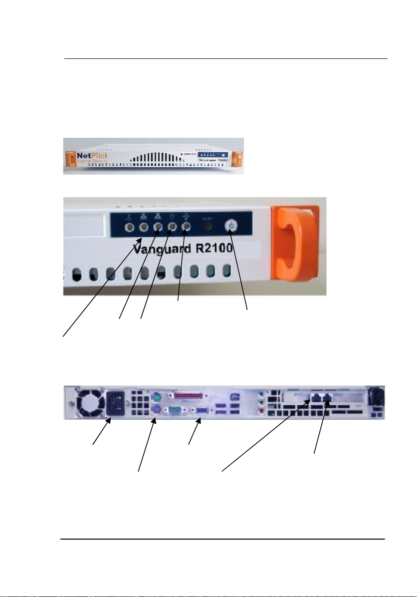
Front and Rear panel NetPilot Vanguard – Rackmount
LAN1 - for Local LAN
VGA Monitor
Power
Keyboard
LAN2 - for Internet
LAN3 - for DMZ
ON/OFF Button
Power
LED
Disk
LED
LAN1
LED
LAN2
LED
Installation
Getting Started – New NetPilot Range 15
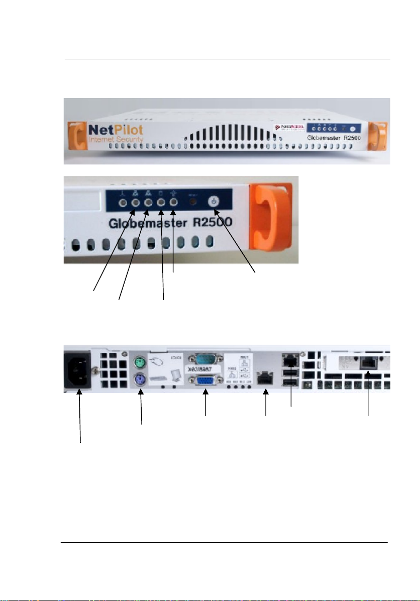
Front and Rear panel NetPilot Globemaster
POWER The electrical mains system input. For power requirements
see table in ‘Technical Information’ section.
Power Provides the unit with switched standby mode for safe
switch power down of the unit.
Power Inlet
LAN1
LAN3
LAN2
Monitor
Keyboard
ON/OFF Button
Power LED
Disk LED
LAN1
LED
LAN2
LED

Installation
Getting Started – New NetPilot Range 16
Caution:
Do not disconnect electrical power from the NetPilot until shut
down is completed.
Only use the power cable supplied with the unit to connect to the
mains power supply. Do not use any other power cable with this
unit. If the plug on the power cable does not match the mains inlet
socket, contact your reseller for further advice.
LAN 1 The 10/100 or 10/100/1000 Ethernet Base-T interface is an
RJ45 socket.It allows direct connection between the
NetPilot and a single piece of equipment. The Ethernet LAN
port simulates the characteristics of a workstation port. This
allows it to be directly connected to a LAN or network hub
port as required.
LAN 2 The 10/100 or 10/100/1000Base-T interface is an RJ45
socket and it is recommended as the connection to an
outside network i.e. Internet. It allows direct connection
between the NetPilot and a single piece of equipment for
example ADSL router or a LAN or network hub port as
required.
LAN 3 10/100 or 10/100/1000 Base-T interface with an RJ45
socket. NetPilot V6 software this is a configurable port for
DMZ or additional LAN use.
Monitor Initial Configuration and diagnostic use only
Keyboard Initial Configuration and diagnostic use only
N.B. All other ports are for diagnostic or future use and not
customer configurable or usable.
Installation
Getting Started – New NetPilot Range 17
Installation
Power connection
Connect the power lead provided to the power connector on the rear
panel of the NetPilot and to a standard mains wall socket.
Do not switch on at this stage.
Only use the power cable supplied with the unit to connect to the
mains supply. Do not use any other power cable with the NetPilot.
If the plug on the power cable does not match the mains socket,
contact your supplier for further advice.
LAN connection
The connection to the 10/100 or 10/100/1000 Base-T Local Area
Network (LAN) may be to a hub or switch, or for diagnostic purposes
directly to a single workstation or PC.
Do not connect an ISDN line to a NetPilot LAN port. The ISDN
voltage can damage the unit.
Connecting to a hub or switch
1. Connect either end of the supplied cable to the LAN 1 socket on the
NetPilot.
2. Connect the other end of the cable to a hub or switch port.
Connecting to a single PC
1. Connect either end of the cable to the LAN 1 socket on the NetPilot.
2. Connect the other end of the cable to the socket on the PC’s
Ethernet adaptor:

Installation
Getting Started – New NetPilot Range 18
Internet connection
If the NetPilot is supplied in addition to LAN2 with one additional or more
LAN interfaces then only one may be selected to operate as the default
Internet connection at any one time.
Connecting via an Ethernet cable/ADSL
1. Connect either end of supplied cable to the LAN 2 socket on the
NetPilot.
2. Connect the other end of the cable to the routing device.
If the router to which the NetPilot is connected provides DHCP services
the NetPilot will automatically obtain the IP addresses necessary to set
up an Internet connection.
Otherwise you will have to configure your connection setting manually in
Network > Connectors using static IP addresses. The LAN2 port address
should be within the IP address range allocated on the LAN side of the
routing device; and not used by any other device. The Gateway address
will be the IP address already allocated to the LAN side of the routing
device that connects, directly or indirectly, to the Internet.
This manual suits for next models
3
Table of contents
Popular Firewall manuals by other brands


Viavi
Viavi Observer Gigastor GS-8P-384T Hardware installation

DigiFlak
DigiFlak Flak installation guide

Draytek
Draytek Vigor2866 Series quick start guide

NETGEAR
NETGEAR FVG318 - ProSafe 802.11g Wireless VPN Firewall 8... Features guide

Draytek
Draytek Vigor2865 Series quick start guide

Watchguard
Watchguard Firebox M5800 quick start guide


