8Go Top ↑
3. Install Graphics/Third-party PCIe Cards
in NA255A-G4
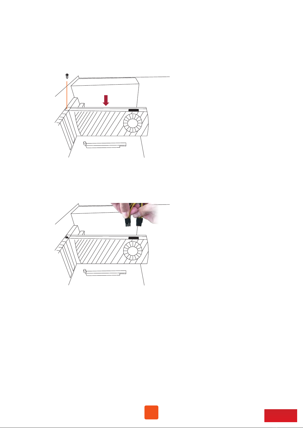
3.1 Procedure for Card Installation
Before card installation in NA255A-G4, read through the following notice and instructions.
The computer’s PCIe slot to be linked with NA255A-G4 must be identified first for the correct
connection between host computer and NA255A-G4.
Two conditions A and B for connection are listed below:
Prior to card installation, make sure NA255A-G4 is disconnected from power source to prevent
electric shock or damage to graphics/third-party PCIe card.
A. If computer’s PCIe slot to be linked with NA255A-G4 is PCIe 4.0 ×16 or PCIe 4.0 x8, you don’t
need to make any change to the switch setting on NA255A-G4 backplane because NA255A-G4
is already set to work with computer’s PCIe 4.0 x16/x8 slot by default.
B. If computer’s PCIe slot to be linked with NA255A-G4 is PCIe 3.0 ×16 or PCIe 3.0 x8, you will
need to set NA255A-G4’s backplane to PCIe Gen3 to have Netstor unit be compatible with
tower Mac Pro (2019) or PCIe Gen3 host computer. The method to set NA255A-G4 backplane
to PCIe 3.0 is given in section 2.3 (SW3) in this user’s manual.
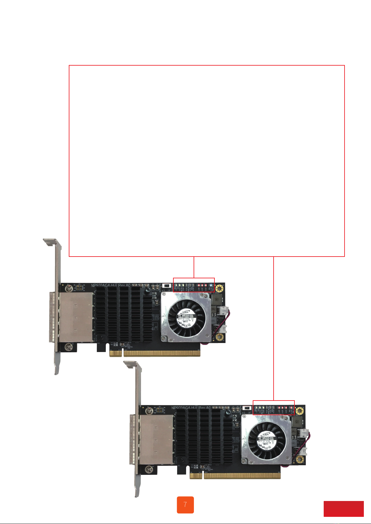
1. Install Netstor NP970AG4-H host card into a PCIe slot on motherboard within server or host
computer.
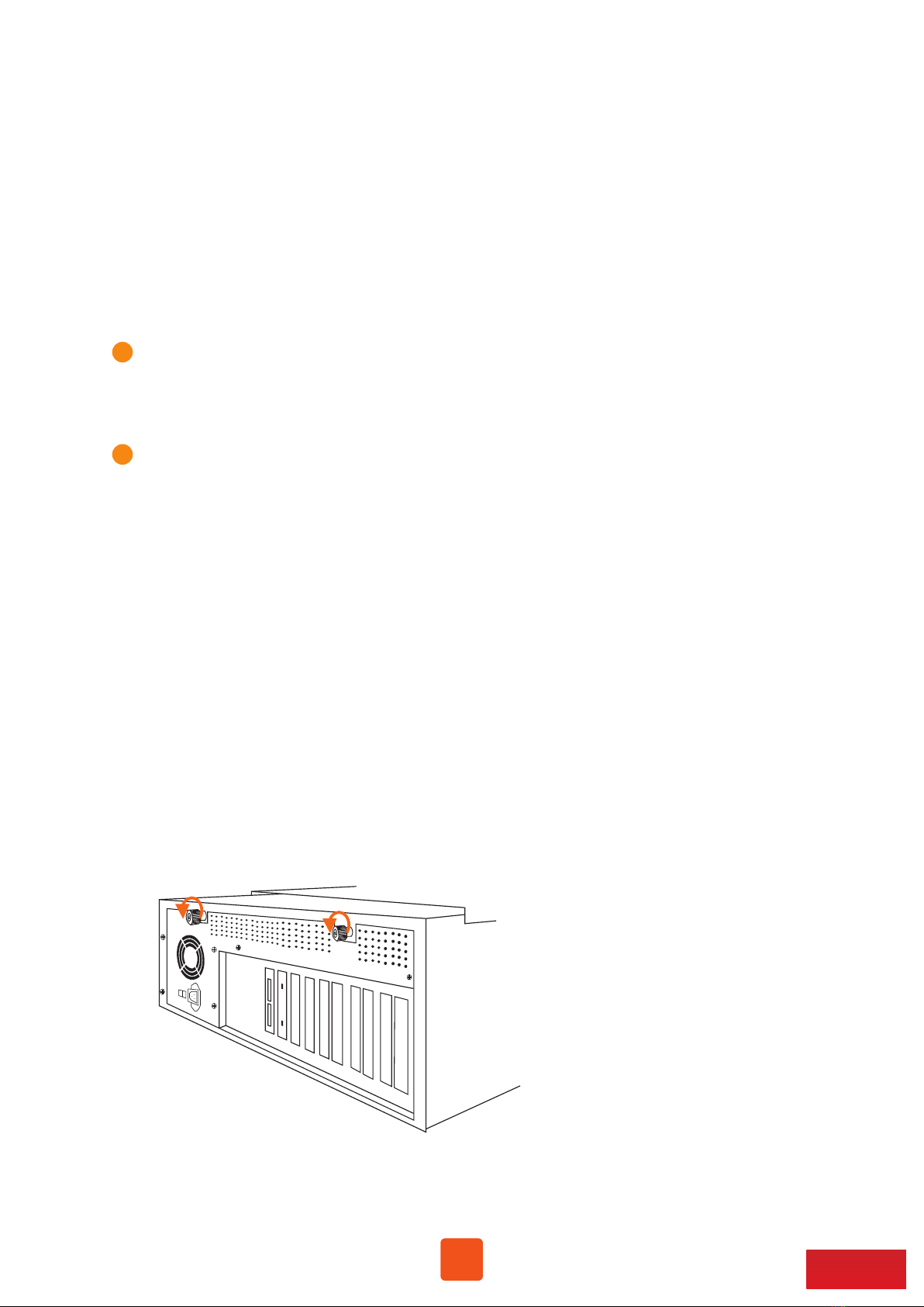
2. Loosen the two thumbscrews and remove the side door of NA255A-G4 chassis.