CriticalConneX™ User Guide - CC2100
Page 3
Getting Started
Before you start the installation you must perform the following steps:
1. Determine were the TAP will be installed into your network. This location
must have access to an approved power outlet (100 to 240 VAC 50/60 Hz).
2. This product can be inserted into either a Gigabit Multi-mode Fiber Link or
Copper Gigabit Link.
3. Obtain cables of the appropriate types and lengths
4. Multi-Mode Fiber Ports are LC Connectors
5. If your devices have ST or SC Connectors, then your multi-mode fiber patch
cables need to be ordered with one connector LC and the other connector ST
or LC.
6. Copper Gigabit Ports are RJ-45 Connectors.
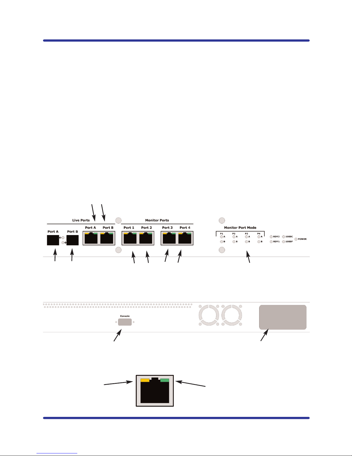
Configuring the TAP
IMPORTANT! The TAP must be configured before it is installed into the network.
1. Plug the power cord into the power supply and into the power inlet on the
rear of the unit. This product comes with dual power supplies. Only one
power supply is required to support the unit.
2. Connect the console cable to the back of the unit and to your computer
(COM1 or COM 2). (DB9 Male to DB9 Female cable)
3. The following configurations are available:
a. Live Ports: Choose Gigabit Multi-Mode Fiber or Copper Gigabit for
your Network Ports
b. Each Copper Gigabit Monitoring Port can be configured to monitor
traffic on Live Port A, Live Port B or Combi (Live Port A & B)
4. Launch HyperTerminal from your computer
a. In MS Windows click START, Run... then type hypertrm and click OK
b. This will bring up a HyperTerminal window
c. Type in a name for the Session and click OK
d. A new window will open. At the bottom of the window click on
CONNECT USING and select the correct COM PORT and click OK
e. This will bring up a PORT SETTING window
f. Set the following values:
i. Bits per Second: 115200
ii. Data Bits: 8
iii. Parity: NONE
iv. Stop Bits: 1
v. Flow Control: NONE
g. Select OK
h. Hit ENTER
i. The login screen below will display: