Network Electronics SDI-IP-GTW User manual

network-electronics.com
SDI to IP
Gateway
Rev. 1.3.0
Flashlink User Manual
SDI-IP-GTW

This page is intentionally left blank

SDI-IP-GTW User Manual
3
Important notice:
Network Ele troni s reserve the right to make orre tions,
modifi ations, enhan ements, improvements and other hanges to its
produ ts or servi es at any time and to dis ontinue any produ t or
servi e without noti e.
About this manual
This manual explains how to operate the SDI-IP-GTW SDI to IP Video
Gateway. It is shown how to install and maintain the unit. In addition,
the fun tionality of the unit is des ribed in detail.
This manual should be kept in a safe pla e for referen e for the life time
of the equipment. Further opies of this manual an be ordered from
Network Ele troni s. If passing the equipment to a third party, please
ensure to pass all relevant do umentation in luding this manual.
Issues of this manual are listed below:
Revision Date Software version Comment
1.0 November 2005 1.0.7 Initial release
1.1 February 2006 1.1.0 Updated and FEC included
1.2 February 2006 1.1.0 Updated some figures
Reformatted the document
1.3 April 2007 1.2.0 Updated with SNMP, IGMPv3, Ping,
RIP, Security
How to use this manual
Novi e users unfamiliar with the Video Gateways from Network
Ele troni s should read this manual starting with Chapter 1. Users
who are familiar with the Network Ele troni s Video Gateways and
operation of video over IP equipment may skip to Chapter 2. Users
whi h are more interested in the fun tionality offered by the SDI-IP-
GTW may dire tly go to Chapter 4.

SDI-IP-GTW User Manual
4
This page is intentionally left blank

SDI-IP-GTW User Manual
5
Table of Contents
1Introduction ................................................................................ 9
1.1
Purpose of this Manual......................................................... 9
1.1.1
Who Should Use this Manual...................................................9
1.1.2
Warnings, Cautions and Notes.................................................9
1.2
Conta t Information ........................................................... 10
1.2.1
What Equipment is overed by this Manual............................10
1.2.2
Software versions ..................................................................11
1.3
Role of the SDI-IP-GTW in a Typi al System ........................ 11
1.4
Summary of Features ......................................................... 11
1.5
Guided Tour....................................................................... 12
1.5.1
The User Interfa e .................................................................12
1.5.2
Front Panel Des ription .........................................................12
1.5.3
Rear Panel Des ription ..........................................................12
1.5.4
Constru tion .........................................................................13
1.5.5
Hardware Options .................................................................13
1.5.6
Software Options...................................................................13
2Installing the Equipment ............................................................ 15
2.1
Introdu tion....................................................................... 15
2.1.1
Read this first!.......................................................................15
2.1.2
To inspe t pa kage ontent....................................................15
2.2
Installing the Equipment .................................................... 15
2.2.1
Sele ting a site for the equipment. .........................................15
2.2.2
To fix the equipment..............................................................16
2.2.3
To able the equipment..........................................................16
2.2.4
Equipment a ess .................................................................16
2.2.5
Ventilation ............................................................................16
2.2.6
To onne t the equipment......................................................17
2.3
Power ................................................................................ 19
2.3.1
AC Power Supply ...................................................................19
2.3.2
Power Cable and Earthing .....................................................19
2.4
Signal Conne tions............................................................. 20
2.4.1
Introdu tion ..........................................................................20
2.4.2
SDI ports ..............................................................................21
2.4.3
Ethernet data port.................................................................22
2.4.4
Ethernet management port ....................................................22
2.5
LEDs ................................................................................. 23
2.6
Powering Up/Down ............................................................ 24
2.6.1
Before Powering up................................................................24
2.6.2
Powering Up ..........................................................................24
2.6.3
Powering Down......................................................................24
3Operating the Equipment ........................................................... 25
3.1
Introdu tion....................................................................... 25
3.2
Changing the IP address of the unit .................................... 25
3.3
Looking at the WEB interfa e.............................................. 25
3.4
Status................................................................................ 27

SDI-IP-GTW User Manual
6
3.5
Devi e Info......................................................................... 29
3.5.1
Network ................................................................................ 31
3.5.2
Time setting .......................................................................... 34
3.5.3
Alarms .................................................................................. 34
3.5.4
SNMP ................................................................................... 35
3.5.5
Ping ...................................................................................... 37
3.5.6
Se urity ................................................................................ 39
3.5.7
RIP-2 (option) ........................................................................ 40
3.6
IP TX ................................................................................. 41
3.6.1
Main ..................................................................................... 42
3.6.2
FEC Settings ......................................................................... 44
3.6.3
VLAN Settings ....................................................................... 46
3.7
IP RX................................................................................. 47
3.7.1
Main ..................................................................................... 47
3.7.2
FEC Settings ......................................................................... 49
3.7.3
VLAN Settings ....................................................................... 51
3.8
Network............................................................................. 51
3.9
Save/Load ......................................................................... 53
3.9.1
Saving a Configuration .......................................................... 54
3.9.2
Loading a Configuration ........................................................ 55
4Equipment Description............................................................... 57
4.1
Introdu tion....................................................................... 57
4.2
Fun tional Des ription ....................................................... 57
4.2.1
Introdu tion.......................................................................... 57
4.2.2
IP Transmit Mode .................................................................. 57
4.2.3
IP Re eive Mode .................................................................... 57
4.2.4
Management ......................................................................... 58
4.2.5
Alarms .................................................................................. 58
4.3
Overview of Video over IP.................................................... 59
4.3.1
Proto ol mapping .................................................................. 59
4.4
Data Flow Blo k Diagrams ................................................. 60
5Pre enti e Maintenance and Fault finding ................................... 63
5.1
Introdu tion....................................................................... 63
5.2
Preventive Maintenan e...................................................... 63
5.2.1
Routine Inspe tion ................................................................ 63
5.2.2
Cleaning ............................................................................... 63
5.2.3
Servi ing............................................................................... 63
5.3
Maintenan e ...................................................................... 64
5.3.1
Warranty .............................................................................. 64
5.4
Fault-finding...................................................................... 64
5.4.1
Fault finding Philosophy........................................................ 64
5.4.2
Preliminary Che ks ............................................................... 64
5.4.3
PSU LED Unlit / Power Supply Problem ................................ 65
5.4.4
Fan(s) Not Working / Overheating ......................................... 65
5.4.5
Alarm LED lit / Alarm ondition ............................................ 66
5.5
Disposing of this Equipment............................................... 66
5.5.1
General................................................................................. 66
5.6
To return the unit .............................................................. 66

SDI-IP-GTW User Manual
7
Appendix A. Glossary 67
Appendix B. Technical Specification ............................................... 71
B.1 SDI port............................................................................................71
B.2 Ethernet data port..............................................................................71
B.3 Ethernet management port ................................................................72
B.4 Alarm relay and maintenance port specification................................72
B.5 AC Mains Input ................................................................................72
B.6 Physical Details ................................................................................72
B.7 Environmental Conditions.................................................................73
B.8 Compliance.......................................................................................73
Appendix C. References ................................................................ 74
Appendix D. Upgrade of Features .................................................. 76
Appendix E. Software upgrade ...................................................... 79
Appendix F. Quality of ser ice – Setting Packet priority................... 81
F.1 MPLS...............................................................................................81
F.2 Layer 3 Routing................................................................................81
F.3 Layer 2 priority.................................................................................82

SDI-IP-GTW User Manual
8
This page is intentionally left blank

SDI-IP-GTW User Manual
9
1Introduction
1.1 Purpose of this Manual
This manual des ribes how to operate the SDI-IP-GTW SDI to IP Video
Gateway hereafter referred to as the SDI-IP-GTW. It is shown how to
install and maintain the unit. A detailed te hni al des ription of the
fun tionality of the unit is given as part of this do ument.
The following topi s are overed in this manual:
•
G
eneral introdu tion to the
SDI-IP-GTW
•Installation of the Unit
•Fun tional des ription of the Unit
•Fault finding and maintenan e
1.1.1 Who Should se this Manual
This manual is written for operators and users of the SDI-IP-GTW. The
SDI-IP-GTW an be onfigured to transmit or re eive a 270 Mbit/s SDI
(Serial Digital Interfa e) stream over an Ethernet/IP link.
This manual provides ne essary information for installation, operation
and day-to-day maintenan e of the unit.
1.1.2 Warnings, Cautions and Notes
1.1.2.1 Heed Warnings
All warnings on the produ t and in the operating instru tions should
be adhered to. The manufa turer an not be held responsible for
injuries or damages where warnings and autions have been ignored or
taken lightly.
1.1.2.2 Read Instructions
All the safety and operating instru tions should be read before this
produ t is operated.
1.1.2.3 Follow Instructions
All operating and use instru tions should be followed.
1.1.2.4 Retain Information
The safety and operating instru tions should be retained for future
referen e.
Warning: This is a warning. Warnings give information, if stri tly
observed, will prevent personal injury and death, or damage to personal
property or the environment.

SDI-IP-GTW User Manual
10
Caution: This is a aution. Cautions give information, if stri tly
followed, will prevent damage to equipment or other goods.
Note: Notes provides supplementary information. They are highlighted
for emphasis, as in this example, and are pla ed immediately after the
relevant text.
1.2 Contact Information
Our primary is to provide first lass ustomer are that is tailored to
your spe ifi business and operational requirements.
Telephone: +47 33 48 99 99
Fax: +47 33 48 99 98
Email: support@network-ele troni s. om
Web: http://www.network-ele troni s. om
Servi e: +47 90 60 99 99
Mailing and visiting address:
Network Ele troni s ASA
Thorøya, P.O. Box 1020
N-3204 Sandefjord
Norway
This manual does not in lude any maintenan e information or
pro edures whi h require the removal of overs.
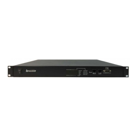
1.2.1 What Equipment is covered by this Manual
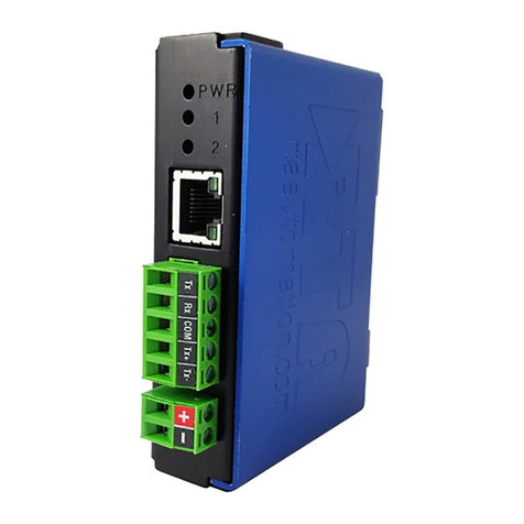
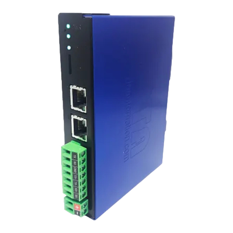
This manual overs the SDI-IP-GTW SDI to IP Video Gateway. Figure 1
shows the physi al unit.
Figure 1. The produ t
The SDI-IP-GTW onsists of a 1U high ra k-mounted en losure with a
DSP module (Master Module) and an SDI I/O board. Opti al Gigabit or
a se ond ele tri al Gigabit port is provided by an optional SFP (Small
Form-Fa tor Pluggable) slot.

SDI-IP-GTW User Manual
11
1.2.2 Software versions
This manual overs the fun tionality of the software version 1.0.8 or
later of the SDI-IP-GTW.
This manual ontinues to be relevant to subsequent software versions
where the fun tionality of the equipment has not hanged. When a new
software version hanges the fun tionality of the produ t, a new version
of this manual is provided.
1.3 Role of the SDI-IP-GTW in a Typical System
The SDI-IP-GTW provides a bridge between the digital video world and
the IP world. The unit provides an interfa e between SDI video signals
to the IP based Network. At the re eption site, the unit re eives the IP
en apsulated data end regenerates the SDI stream.
Figure 2 provides an overview of the SDI-IP-GTW in transmit and
re eive mode.
IP TX IP RX
IP
Network
Management
Network
SDI signal SDI signal
Figure 2. SDI-IP-GTW in a system
1.4 Summary of Features
Features of the SDI-IP-GTW in lude:
•Transmission of un ompressed SDI over Gigabit Ethernet.
oTransparent 10 bit video
oEmbedded audio
oTransparent transmission of all an illary data formats
in luding SDTI
•Flexible Forward Error Corre tion
oIn reased robustness against network pa ket losses
•Very low delay
oNo en oding delay introdu ed, minimal buffering at transmitter
and re eiver
•User-friendly onfiguration and ontrol

SDI-IP-GTW User Manual
12
oWEB/XML based remote ontrol
oEasy a ess to unit from any WEB browser
oEasy integration to Network Management System (NMS) with
SNMP Trap support
1.5 Guided Tour
1.5.1 The ser Interface
All onne tors are provided at the rear panel. Configuration and
monitoring of the unit is performed via a FLASH-based WEB interfa e
using a standard WEB browser su h as Internet Explorer. The unit also
supports onfiguration via upload of XML onfiguration files. On e
onfigured, the unit runs without the need for further intervention
unless system onfiguration requirement hange.
1.5.2 Front Panel Description
The front panel provides four LEDs per SDI-IP-GTW. Table 1 des ribes
the meaning of the different LED indi ators.
Table 1. Front panel LEDs
Indicator Colour Description
Power Green This LED is lit when power is being received by the
unit.
Alarm Red This LED is lit when a failure is detected by the unit.
I.e. at least one alarm with severity level "Critical" is
present.
IP TX Blue This LED is lit when the unit is configured to transmit
data to the IP Network.
IP RX Yellow This LED is lit when the unit is configured to receive
data from the IP Network
1.5.3 Rear Panel Description
All onne tors to the SDI-IP-GTW are provided at the rear panel. Figure
3 shows the rear panel of a SDI-IP-GTW equipped.
1. SDI in. In IP Tx mode, the onne tor provide a SDI input. In IP Rx
mode, the onne tor provides an SDI input for digital Genlo k input.
2. SDI output. In IP Rx mode, the onne tors provide an SDI output.
When no data is re eived on the IP data port a bla k pi ture is
transmitted.
3. SDI test. In IP Tx mode, the onne tor provide a loop-through SDI
output. In IP Rx mode, the onne tor provides an SDI output.
4. Management port. The SDI-IP-GTW provides one Ethernet port for
ontrol and management of the unit.

SDI-IP-GTW User Manual
13
5. Ethernet data port. The SDI-IP-GTW provides one Ethernet data
port for high speed signal transmission and re eption.
6. Alarm/RS232 onnector. This 9-pin male DSub onne tor provides
RS232 a ess and alarm information.
7. Technical Earth. The SDI-IP-GTW provide a Te hni al Earth.
8. Mains Power onnection. This is the Power Supply Conne tion.
9. LEDs. The SDI-IP-GTW provides on the rear four LEDs related to the
operation of the equipment. In addition, there are LEDs related to the
SDI ports, the management port and the data port.
1.5.4 Construction
The SDI-IP-GTW SDI to IP Video Gateway onsists of a main board and
an SDI board mounted horizontally in a s reened abinet. The unit is
1RU high and two units an be mounted side-by-side in a 19 in h ra k.
All inputs and outputs are available at rear panel and there are no
front panel keypads or display. Figure 3 shows the rear panel of the
unit.
Figure 3. Rear view
1.5.5 Hardware Options
1.5.5.1 SFP Module
As a fa tory option, the SDI-IP-GTW an be equipped with an SFP slot
to feature opti al Gigabit or a se ond, redundant ele tri al Gigabit port.
The SFP module itself is not provided.
1.5.6 Software Options
The following table des ribes the features available as software option.
Please refer to

SDI-IP-GTW User Manual
14
Upgrade of Features for more information
Table 2. Fun tionality enabled through software li enses
Functionality Max value Description
Forward Error Correction: NA Pro-MPEG Forward Error Correction
enabled for use on the transmitted stream.
VLAN tagging: NA VLAN tagging enabled for use on all
streams.
SNMP: NA SNMP control of the unit.

SDI-IP-GTW User Manual
15
2Installing the Equipment
2.1 Introduction
2.1.1 Read this first!
The SDI-IP-GTW must be handled arefully and thoughtfully to prevent
safety hazards and damage. Ensure that the personnel designated to
install the unit have the appropriate skills and knowledge.
Follow the instru tions for installation and only use installation
a essories re ommended by the manufa turers.
2.1.2 To inspect package content
•Inspe t the shipping ontainer for damage. If your shipping
ontainer is damaged, keep the shipping ontainer or ushioning
material until you have inspe ted the ontents of the shipment for
ompleteness and have he ked that the SDI-IP-GTW
me hani ally and ele tri ally.
•Verify that you re eived the following items and any optional
a essories you may have ordered:
oSDI-IP-GTW
oPower ord
oUser’s manual
2.2 Installing the Equipment
2.2.1 Selecting a site for the equipment.
As with any ele tri devi e, you should pla e the SDI-IP-GTW where it
will not be subje ted to extreme temperatures, humidity, or
ele tromagneti interferen e.
Specifically, the site you select should meet the following requirements:
•The ambient temperature should be between 0 to 50 degrees
Celsius (32 and 104 degrees Fahrenheit).
•The relative humidity should be less than 90 per ent, non-
ondensing. Do not install the unit in areas of high humidity or
where there is danger of water ingress.
•Surrounding ele tri al devi es should not ex eed the
ele tromagneti field (RFC) standards for IEC 801-3, Level 2
(3V/M) field strength.
•Make sure that the equipment re eives adequate ventilation. Do
not blo k the ventilation holes on ea h side of the SDI-IP-GTW.
•The power outlet should be within 1.8 meters (6 feet) of the SDI-
IP-GTW.

SDI-IP-GTW User Manual
16
•Where appropriate ensure that this produ t has an adequate level
of lightning prote tion. Alternatively, during a lightning storm or
whenever it is left unattended and unused for long periods of time,
unplug it from the supply outlet and dis onne t the output
equipment. This prevents damage to the produ t due to lightning
and power-line surges.
Warning: If the Video Gateway has been subje t to a lightning strike or
the power surge whi h has stopped it working, dis onne t the power
immediately. Do not reapply power until it has been he ked for safety.
If in doubt, onta t Network Ele troni s.
2.2.2 To fix the equipment
The SDI-IP-GTW is designed for stationary use. The SDI-IP-GTW is
designed for installation in standard 19" ra ks. When installed in a
ra k, ensure that the unit is surely and safely installed and that the
equipment has adequate through-flow of air.
2.2.3 To cable the equipment
Ensure that power supply ables are routed in su h a way that they are
not likely to be walked on or pin hed by items pla ed upon or against
them.
Do not run a power ables and signal ables in the same du t.
2.2.4 Equipment access
The SDI-IP-GTW has onne tors at the rear. When installing the unit,
ensure that the unit is installed to allow easy a ess to the rear of the
unit.
2.2.5 Ventilation
Warning: Never push obje ts of any kind into this equipment through
openings as they may tou h dangerous voltage points or short-out
parts that ould result in a fire or ele tri sho k. Never spill liquid of
any kind on or into the produ t.
Please observe the following:
1. Openings in the abinet are provided for ventilation and to ensure
reliable operation of the produ t and to prote t it from overheating, and
these openings must not be blo ked or overed. This produ t should
never be pla ed near or over a radiator or heat register. This produ t
should not be pla ed in a built-in installation su h as a ra k unless
proper ventilation is provided or the instru tions have been adhered to.
2. The fans ontained in this unit are not fitted with dust/inse t filter.
Play parti ular attention to the environment in whi h it is to be used.

SDI-IP-GTW User Manual
17
The SDI-IP-GTW should be installed to allow adequate flow of free-air.
Ensure that the ventilation holes on ea h side of the SDI-IP-GTW are
not blo ked and allow at least 50 mm free air-spa e at ea h side of the
unit. The SDI-IP-GTW is designed to be sta ked in 19"ra ks without
ventilation panels between. In systems with sta ked units, it may be
required to use for ed-air ooling to redu e the operating ambient
temperature.
Figure 4 shows the air path through the unit.
Figure 4. Air Path though the unit
2.2.6 To connect the equipment
On e the SDI-IP-GTW is installed in its intended operating position, it
is ready to be onne ted to the rest of the system provided that this is
already in pla e. The following figure shows the different equipment
onne tions.
Figure 5. Signal onne tions
Remove mains supply previous to move or install the equipment.
Ensure ESD pre autions are observed whilst inter onne ting
equipment.
2.2.6.1 SDI port
The SDI-IP-GTW an be operated in two modes: IP Transmit and IP
Re eive mode.

SDI-IP-GTW User Manual
18
Figure 6. Conne tor usage in the two operating modes
In IP transmit mode, the equipment re eives an SDI stream and sends
it to the IP network. In this mode, onne t the SDI input signal to
onne tor 1 marked with SDI IN. For test purposes, the input signal is
looped to output onne tor 4.
In IP re eive mode, the equipment re eives an IP stream and sends the
SDI stream out on the two SDI OUT onne tors, numbered 2 and 3.
Conne tor 4 is intended for test purposes. Conne tor 1 (SDI IN) is
optionally used for an input referen e signal. The phase and rate of the
output signal may be lo ked to this input referen e signal.
2.2.6.2 Ethernet data port
Conne t the Ethernet data port to the network. In IP transmit mode,
the SDI-IP-GTW will send an IP stream to the network. In IP re eive
mode, the SDI-IP-GTW will re eive an IP stream from the network.
2.2.6.3 Power supply
Se tion 2.3 provides details of the power supply, prote tive earthing
and se urity. Read all these instru tions, prior to onne ting the unit to
power mains.
2.2.6.4 Management port
The SDI-IP-GTW provides one Ethernet port for ontrol and
management. Conne t the management port to the management
network.
2.2.6.5 Technical Earth
Conne t the Te hni al earth to a suitable earthing point.
2.2.6.6 Alarm
The SDI-IP-GTW provides an alarm relay for onne tion to external
alarm system.

SDI-IP-GTW User Manual
19
2.3 Power
2.3.1 AC Power Supply
Warning: This produ t should be operated only from the type of power
sour e indi ated on the marking label. Please onsult a qualified
ele tri al engineer or your lo al power ompany if you are not sure of
the power supply to your business.
The SDI-IP-GTW provides a wide-ranging power supply overing a rate
voltage range 100-240Va , 50/60Hz. Please refer to Te hni al
Spe ifi ation for a detailed spe ifi ation of the power supply.
2.3.2 Power Cable and Earthing
2.3.2.1 General
Ensure that the AC power able is suitable for the ountry in whi h the
unit is to be operated.
Warning: If the moulded plug fitted to the mains able supplied with
this unit is not required, please dispose of it safely. Failure to do this
may endanger life as live ends may be exposed if the removed plug is
inserted into a mains outlet.
Caution: Power supply ords should be routed so that they are not
likely to be walked on or pin hed by items pla ed upon or against
them, paying parti ular attention to ords at plugs, onvenien e
re epta les, and the point where they exit from the applian e.
The unit is supplied with a two meter deta hable mains supply able
equipped with the moulded plug suitable for Europe, UK or US.
The wires in the mains able are oloured in a ordan e with the wire
olour ode shown in Table 3.
Table 3. Supply Cable wiring olours
UK (BS 1363) EUROPE (CEE 7/7) USA (NEMA 5-15P)
Earth: Green-and yellow Green-and yellow Green
Neutral: Blue Blue White
Live: Brown Brown Black
2.3.2.2 Protecti e Earth /Technical Earth
To a hieve prote tion against earth faults in the installation, onne ted
to the equipment by signal ables et ., the equipment should always be
onne ted to prote tive earth. If the mains applian e oupler is
dis onne ted while signal ables are onne ted to the equipment, earth

SDI-IP-GTW User Manual
20
onne tion should be a hieved by onne ting earth to the additional
te hni al earth onne tion on the rear panel of the unit.
Warning: This unit must be orre tly earthed through the moulded
plug supplied. If the lo al mains supply does not have an earth
ondu tor do not onne t the unit.
Caution: Consult the supply requirements in Te hni al Spe ifi ation
prior to onne ting the unit to the supply.
The unit has a Te hni al Earth terminal lo ated at the rear panel. Its
use is re ommended. This is not a Prote tive earth for ele tri al sho k
prote tion. The terminal is provided to:
1. Ensure all equipment hassis fixed in the ra k are at the same
Te hni al earth potential. To a hieve this, onne t a wire between the
Te hni al earth terminal and a suitable point on the ra k.
2. Eliminate the migration of stray harges when onne ting between
equipment.
Warning: If the terminal s rew has to be repla ed, use an M4x12mm
long pozidriv panhead. Using a longer s rew may ause a safety hazard.
2.3.2.3 Connecting the Video Gateway to the AC Power Supply
Warning: Do not overload wall outlets and extension ords as this an
result in a risk of fire or ele tri al sho k. As no mains swit h is fitted in
this unit, ensure that the lo al a power supply is swit h off before
onne ting the supply ord. The unit is not fitted with an on/off swit h.
Ensure that the so ket-outlet is installed near the equipment so that is
easily a essible. Failure to isolate the equipment properly may ause a
safety hazard.
To onne t the unit to the lo al AC power supply:
1. Ensure that the lo al a power supply is swit h OFF.
2. Conne t the a power lead to the Video Gateway mains input
onne tor and then the lo al mains supply.
2.4 Signal Connections
2.4.1 Introduction
All signal onne tors are lo ated at the rear of the SDI-IP-GTW. For
detailed spe ifi ations of the different interfa es, please refer to Chapter
5.6Appendix B.
Please ensure that spe ified ables are used in order to ensure signal
integrity and omplian e with EMC requirements.
Table of contents
