manuals.online logo
Brands
  1. Home
  2. •
  3. Brands
  4. •
  5. enphase
  6. •
  7. Gateway
  8. •
  9. enphase ENV-S-EM-230-LF-KIT User manual

enphase ENV-S-EM-230-LF-KIT User manual

QUICK INSTALL GUIDE-EN
Installing the IQ Gateway Metered
and EMI Line Filter Kit
To install the IQ Gateway Metered with integrated meter and the EMI Line Filter Kit, read and follow all warnings and instructions in
this guide and the IQ Gateway Metered Installation and Operation Manual at https://enphase.com/contact/support. Safety warnings are
listed at the end of this guide.
PREPARATION
A ) Download the latest version of the Enphase Installer App
and log in to your Enphase Installer App account. With
this app, you can connect to the IQ Gateway Metered
to track system installation progress. To download, go
to https://enphase.com/installers/apps or scan the QR
code at the right.
B ) Check the box for the following items:
• IQ Gateway Metered
• Two split-core Current Transformers (CTs) for production and
consumption metering
• DIN rail for mounting
• Quick Install Guide (this document)
• EMI Line Filter
C ) Check that there is space in the switchboard to install CTs. Do not
install the CTs in a panel where they exceed 75% of the wiring space
of any cross-sectional area within the panel.
D ) Install the IQ Gateway Metered in an IP54-rated, or better enclosure
with conduit attachment when installing outdoors. Do not drill
holes on the top of the enclosure or anywhere that allows moisture
ingress. Metallic enclosures may impair Wi-Fi signal strength. Use
an appropriately rated enclosure if installing the IQ Gateway Metered
indoors.
E ) If you are installing the IQ Gateway Metered in a multi-phase applica-
tion, make sure you have the following items:
• Additional CTs (CT-100-SPLIT-ROW) for multi-phase installations.
Make sure you have one CT for each phase monitored, for both
production and consumption.
• The IQ Gateway box contains a label to identify the line on which
a CT is installed. Stick a small label denoting the line on a CT and
wrap the corresponding bigger label on the end of the lead wire
after stripping, and install the CT on the appropriate line.
• A phase coupler. If installing on a three-phase site, install a phase
coupler on the load side of the overcurrent protection device.
See the Technical Brief on Phase Coupling for your region at
https://enphase.com/contact/support. Consult Enphase Support
for compatible devices.
F ) Decide how to connect the IQ Gateway Metered to the internet:
choose to use Wi-Fi, a Mobile Connect modem, or Ethernet.
G ) Make sure you have the following optional items, if needed:
• Mobile Connect modem (order CELLMODEM-02)
• Ethernet cable [802.3, Cat5E or Cat6, unshielded twisted pair
(UTP)]. Do not use shielded twisted pair (STP) cable.
H ) Install the PV system as directed by the installation manuals.
I ) If an Enphase PV system is or will be installed at the site, create a
paper installation map to record device serial numbers and positions
in the array. Scan this map later using the Enphase Installer App and
your mobile device.
• As you did with the microinverters (and Enphase AC batteries, if in-
stalled), peel the removable label from the bottom of the IQ Gateway
Metered and afx it to the paper installation map.
• Always keep a copy of the installation map for your records.
NOTE: If needed, you can nd an installation map with any Enphase
Microinverter Quick Install Guide.
NOTE: RCD is recommended to be installed on-site for fault
protection. Follow local regulations on installing RCD on-site with
IQ Gateway and IQ Series Microinverters.
(Model ENV-S-EM-230-LF-KIT)
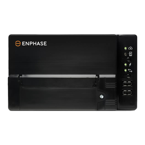
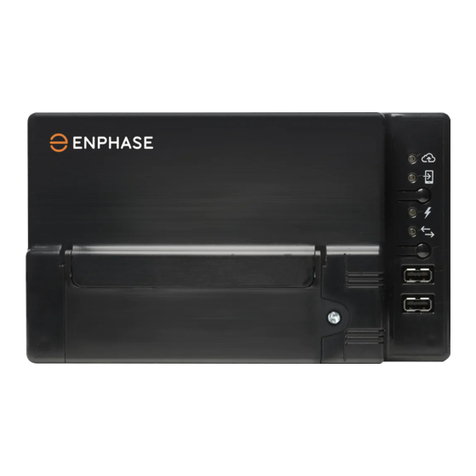
IQ Gateway Metered display and controls
Network communications LED
Green when IQ Gateway Metered is
connected to Enphase Installer App.
AP mode LED
Green when IQ Gateway’s AP Wi-Fi
network is available.
AP mode button
Press to enable IQ Gateway’s AP Mode
for connecting with a mobile device.
Hold for 5 seconds to start WPS
connection to a router.
Power production LED
Green when microinverters are
producing power.
Device communications LED
Green when devices are
communicating with IQ Gateway Metered.
Device scan button
Press to start/stop 15-minute scan for
devices over the power line.
Track system installation progress with the Enphase Installer App mobile
app. The LEDs on the IQ Gateway Metered are solid green when a function
is enabled or performing as expected, ashing when an operation is in
progress, or solid red when troubleshooting with Enphase Installer App is
required. For a legend of all LED states, see Troubleshooting a.
Enphase Installer
App
How it works
POWER LINE
COMMUNICATIONS
NETWORK
COMMUNICATIONS
Microinverters
IQ Gateway
Metered
Switchboard
Router
Enphase
Installer
Platform
To Internet
Enphase Support: https://enphase.com/contact/support
SAFETY
Safety and advisory symbols
DANGER: This indicates a hazardous situation, which if not avoided, will result
in death or serious injury.
⚠WARNING: This indicates a situation where failure to follow instructions may
be a safety hazard or cause equipment malfunction. Use extreme caution and
follow instructions carefully.
✓NOTE: This indicates information particularly important for optimal system
operation. Follow instructions carefully.
Safety instructions
DANGER: Risk of electric shock. Risk of re. Do not attempt to repair the
IQ Gateway Metered; it contains no user-serviceable parts. Tampering with
or opening the IQ Gateway Metered will void the warranty. Warranty void if
cover removed. If the IQ Gateway Metered fails, contact Enphase Support for
assistance (https://enphase.com/contact/support).
DANGER: Risk of electrocution! Do not install CTs when current is owing
in the sensed circuit. Always install CT wires in the terminal blocks before
energising the sensed circuit.
DANGER: Risk of electric shock. Do not use Enphase equipment in a manner
not specied by the manufacturer. Doing so may cause death or injury to
persons or damage to equipment.
DANGER: Risk of electric shock. Be aware that installation of this equipment
includes risk of an electric shock. If you wire the IQ Gateway Metered at the
sub-board, always de-energise the sub-board before beginning.
DANGER: Risk of electric shock. Risk of re. Only qualied personnel should
troubleshoot, install, or replace the IQ Gateway Metered.
DANGER: Risk of electric shock. Risk of re. Do not wire unused terminals or
terminal blocks on the IQ Gateway Metered.
DANGER: Risk of electric shock. Risk of re. Only qualied personnel should
clean and service the IQ Gateway.
⚠WARNING: Before installing or using the IQ Gateway Metered, read all
instructions and cautionary markings in the technical description and on the
IQ Gateway Metered.
⚠WARNING: Risk of equipment damage. If installing the IQ Gateway Metered in
an enclosure, choose an area for installation where the ambient temperature
does not exceed 46ºC.
✓NOTE: Do not install the CTs in a panel where they exceed 75% of the wiring
space of any cross-sectional area within the panel or refer to local standards
for guidance.
✓NOTE: Perform all electrical installations in accordance with all national and
local electrical codes.
✓NOTE: To ensure optimal reliability and to meet warranty requirements, the IQ
Gateway Metered must be installed according to the instructions in this guide.
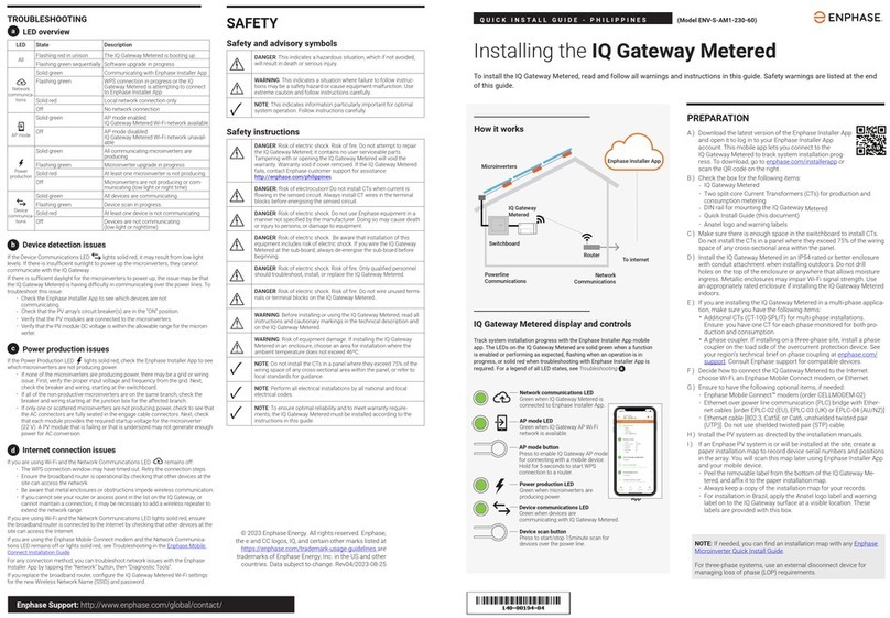
TROUBLESHOOTING
aLED overview
LED State Description
All Flashing red in unison The IQ Gateway Metered is booting up
Flashing green sequentially Software upgrade in progress
Network
communica-
tions
Solid green Communicating with the Enphase Installer
App
Flashing green WPS connection in progress or the IQ
Gateway Metered is attempting to connect
to the Enphase Installer App
Solid red Local network connection only
Off No network connection
AP mode
Solid green AP mode enabled:
IQ Gateway Metered Wi-Fi network is
available
Off AP mode disabled:
IQ Gateway Metered Wi-Fi network is
unavailable
Power
production
Solid green All communicating microinverters are
producing
Flashing green Microinverter upgrade in progress
Solid red At least one microinverter is not producing
Off Microinverters are not producing or com-
municating (low light or nighttime)
Device
communica-
tions
Solid green All devices are communicating
Flashing green Device scan in progress
Solid red At least one device is not communicating
Off Devices are not communicating
(low light or nighttime)
bDevice detection issues
If the Device communications LED lights are solid red, it may be a result of low
light levels. If there is not enough sunlight to power up the microinverters, they cannot
communicate with the IQ Gateway.
If there is sufcient daylight for the microinverters to power up, the issue may be that
the IQ Gateway Metered is having difculty communicating over the power lines. To
troubleshoot this issue:
• Check the Enphase Installer App to see which devices are not
communicating.
• Check that the circuit breaker(s) for the PV array are in the “ON” position.
• Verify that the PV modules are connected to the microinverters.
• Verify the PV module DC voltage is within the allowable range for the microinverter.
cPower production issues
If the Power production LED lights are solid red, check the Enphase Installer App to
see which microinverters are not producing:
• If none of the microinverters are producing power, there may be a grid or wiring
issue. First, verify that there is proper input voltage and frequency from the grid.
Next, check the breaker and wiring, starting at the switchboard.
• If all of the non-productive microinverters are on the same branch, check the
breaker and wiring starting at the junction box for the affected branch.
• If only one or scattered microinverters are not producing power, rst check to see
that the AC connectors are fully seated in the IQ Cable connectors. Next, check
that each module is providing the required startup voltage for the microinverter.
A PV module that is failing or that is undersized may not generate enough power
for AC conversion.
dInternet connection issues
If you are using Wi-Fi and the Network communications LED remains OFF:
• The WPS connection window may have timed out. Retry the connection steps.
• Make sure that the broadband router is operational by checking that other devic-
es at the site can access the network.
• Be aware that metal enclosures or obstructions impede wireless communication.
• If you cannot see your router or access point in the list on the IQ Gateway, or
cannot maintain a connection, it may be necessary to add a wireless repeater to
extend the network range.
If you are using Wi-Fi and the Network communications LED lights solid red, make sure
that the broadband router is connected to the Internet by checking that other devices
at the site can access the Internet.
If you are using the Mobile Connect modem and the Network communications LED
remains off or lights solid red, see Troubleshooting in the Mobile Connect Installation
Guide.
For any connection method, you can troubleshoot network issues with the Enphase
Installer App by tapping the Network button, then Diagnostic Tools.
If you replace the broadband router, congure the IQ Gateway Metered Wi-Fi settings
for the new Wireless Network Name (SSID) and password.
© 2023 Enphase Energy. All rights reserved. Enphase, the e and CC logos, IQ, and
certain other marks listed at https://enphase.com/trademark-usage-guidelines are
trademarks of Enphase Energy, Inc. in the US and other countries. Data subject to
change. 2023-12-20
Compliance with EU Directives
This product complies with the following EU Directives and can be used in the
European Union without any restrictions.
• Electro magnetic compatibility (EMC) directive 2014/30/EU
• Low Voltage Directive (LVD) 2014/35/EU
• Restriction of Hazardous Substances (RoHS) 2011/65/EU
RED Directive Compliance
Hereby, Enphase Energy Inc. declares that the radio equipment type IQ Gateway
Metered follows Directive 2014/53/EU.
The full text of the EU (DoC) is available at:
https://enphase.com/en-gb/installers/resources/documentation
Manufacturer:
Enphase Energy Inc., 47281 Bayside Pkwy, Fremont, CA, 94538,
The United States of America. PH: +1 (707) 763-4784
Importer:
Enphase Energy NL B.V., Het Zuiderkruis 65, 5215MV,
‘s-Hertogenbosch, The Netherlands, PH: +31 73 3035859
Note for third-party products
Any third-party manufacturer or importer product(s) used to install or commis-
sion Enphase product(s) shall comply with the applicable EU Directive(s) and
requirements in the European Economic Area (EEA). It is the responsibility of
the installer to conrm that all such products are labelled correctly and have the
required compliant supporting documentation.
Wireless module details
Module type: WG7837V0 Wi-Fi & Bluetooth Module 13.4 mm×13.3 mm, LGA-100
Frequency band: 2.4 GHz and 5.0 GHz
Max power transmitted: 20 dBm
Wire the IQ Gateway Metered for power and metering
For this step, refer to the Wiring Instruction Sheet for your region.
Energize the IQ Gateway Metered
A ) Close the terminal block door, and secure it with the screw.
B ) Turn on the circuit feeding the IQ Gateway Metered.
C ) All four LEDs ash red during boot-up (approximately 2 minutes). When boot-up
is complete, the Device communications LED lights solid red, indicating
that devices are not yet detected.
Launch Enphase Installer App and start system activation
A ) Launch Enphase Installer App. To create an activation for a new system, tap
Plus on the bottom right corner of the screen.
B ) Tap System Details to enter the required information.
C ) Complete the system activation in the Enphase Installer App by lling in the
details. The System created successfully message will display at the bottom of
your screen, and system details will appear now as complete.
Adding devices and array to the system
This step is used to enter the unique serial numbers of all devices present on-site. It
is recommended that you enter the serial number by scanning the barcode/QR code.
A ) Tap Devices and Array on the home page.
B ) Add the total number of devices to be installed in your system.
C ) Scan device serial numbers through the bar code or QR code in the respective
device sections.
In addition to using your device’s camera to scan serial numbers, you can enter
the serial numbers manually. Manual entry should be used only when you are
not able to scan the bar code or QR code of any device.
D ) After scanning microinverters, you can use Array Builder to assign your scanned
microinverters to an array or build an array manually.
This step can also be completed post-commissioning.
Setting the tariff details (optional)
This step is used to enter the electricity rate structure of the utility.
A ) Tap Tariff & Storage Conguration on the home page.
B ) Subsequently, tap Tariff Editor to enter the electricity import or export rate.
Ensure that the device is connected to the internet to complete this step.
IQ Gateway connectivity
This step is used to establish/monitor IQ Gateway connectivity to the Enphase
Cloud and Enphase Installer App. You can also update IQ Gateway in this step if it is
needed for successful commissioning.
A ) Tap IQ Gateway Connectivity on the Enphase Installer App home page.
B ) If the IQ Gateway and the Enphase Installer App (or the phone icon) are not
connected, follow these steps:
- On the IQ Gateway, press the AP mode button (the rst button from the top) for
about one second. The LED will light solid green.
- Go to your phone’s settings and connect to IQ Gateway’s Wi-Fi network.
- Return to the Enphase Installer App IQ Gateway Connectivity page and con-
nect.
C ) If the IQ Gateway and Enphase Cloud (or the cloud icon) are not connected,
follow these steps:
- The IQ Gateway can connect to Enphase Cloud through either Wi-Fi, Ethernet,
or cellular.
- If Wi-Fi is selected, input the username and password for the home/ofce
Wi-Fi.
- If connecting using Ethernet, simply plug the cable into the IQ Gateway.
Provisioning the devices
To provision your devices, the Enphase Installer App should be connected to IQ
Gateway via AP mode, as described in the IQ Gateway Connectivity section.
A ) If a green checkmark displays between the IQ Gateway and Enphase Installer
App, tap START PROVISIONING DEVICES. The Provisioning Devices screen
displays the steps executed by the Enphase Installer App. The Enphase Installer
App veries and updates the grid prole in IQ Gateway and provisions all the
connected devices.
B ) When provisioning is complete, tap DONE.
Verify meter conguration
The production meter can be congured as per the following steps:
A ) Tap Meter Conguration to start conguring the consumption and production
meter.
B ) Subsequently, tap on the Production Meter to start conguring production
meters. A pop-up message appears asking you to follow the meter wizard to
verify your CT conguration. Select Yes to proceed.
C ) Tap Enable production meter to nish the conguration of the production
meter.
The consumption meter can be congured as per the following steps:
A ) Tap Meter Conguration to start conguring consumption and production
meter.
B ) Subsequently, tap Consumption Meter to start conguring production meters.
A pop-up message appears asking you to follow the meter wizard to verify your
CT conguration. Select Yes to proceed.
C ) Tap Enable consumption meter to nish the conguration of consumption
meter.
Send summary report and complete homeowner
walkthrough
This step is used to download the summary report of all the devices installed and
report to IQ Gateway. You can share this report using email, text, or airdrop. It
contains details of each provisioned device and the commissioned status of the
system.
A ) Tap Summary on the Enphase Installer App Home page. The system report
is displayed on the screen, which consists of a list of devices, their serial
numbers, their last reports, and information about the grid prole applied to
the devices.
B ) Tap SHARE on the top right corner to share the report as needed.
C ) Open Homeowner Walkthrough and discuss all listed points with the home-
owner. You can also show the videos embedded in the links to the homeowner
for a better experience.
INSTALLATION
Choose a location for the IQ Gateway Metered
A ) Install the IQ Gateway Metered near the switchboard and consider the length
of the CT leads (4 meters) when choosing the location. If you need to extend
the leads (up to 148 meters), refer to the IQ Gateway Metered Installation and
Operation Manual at https://enphase.com/contact/support.
B ) Install the IQ Gateway Metered in a protected dry space. If outdoors, install
the IQ Gateway Metered in an IP54-rated, or better, enclosure with conduit at-
tachment. Use an appropriately rated enclosure if hard wiring the IQ Gateway
Metered indoors.
NOTE: Metallic enclosures may impair Wi-Fi signal strength.
C ) Mount the IQ Gateway Metered horizontally using the included DIN rail.
6
5
4
8
7
1
2
3
9
10
A) Before running CT wires through the conduit, use coloured tape to mark each
of the CTs and the free ends of its wires with a different colour. You can run
multiple CT wires through a single conduit.
B ) Wire the IQ Gateway Metered for power.
• Depending on the number of phases you will wire, use a one-pole, two-
pole, or three-pole (20 A maximum) circuit breaker for the supply wiring.
• Make sure the supply wiring is 2.5 mm2copper rated at 75ºC or better.
• Locate the screw on the terminal block door, and loosen it with a screw-
driver to unlock the door and ip it open.
• Connect Line 1 to L1, Line 2 to L2, Line 3 to L3, and Neutral to N, as
required.
• Tighten all connections to 0.56 N m.
C ) Install the Production CTs on phases as required:
• Locate the arrow on the CT label.
• To monitor production on Line 1:
- Connect the white wire to the “I1•” terminal and the blue wire to the “I1”
terminal.
- Clamp the CT on active Line 1 of the solar production circuit with the
arrow pointing toward the load (away from the solar array).
• To monitor production on Line 2:
- Connect the white wire to the “I2•” terminal and the blue wire to the “I2”
terminal.
- Clamp the CT on active Line 2 of the solar production circuit with the
arrow pointing towards the load (away from the solar array).
• To monitor production on Line 3:
- Connect the white wire to the “I3•” terminal and the blue wire to the “I3”
terminal.
- Clamp the CT on active Line 3 of the solar production circuit with the
arrow pointing towards the load (away from the solar array).
• Tighten all connections to 0.56 N m.
D ) Install the Consumption CTs in phases as required:
• Locate the arrow on the CT label.
• Make sure that the AC mains wire(s) are de-energised until you have
secured the CT wires in the terminal blocks.
NOTE: Only run active conductors of the same phase through each CT.
Each CT can monitor multiple active conductors.
• To monitor consumption on Line 1:
- For the rst CT, connect the white wire to “I1•” and the blue wire to “I1”.
- Clamp the CT on the main supply Line 1 (active). When the Consump-
tion CT is on Line 1 (active) conductor, the arrow must point towards the
load (away from the grid).
NOTE: Due to variance in switchboard design and main power feed, there may not always be
enough space to install CTs.
Match CT and voltage sense phases. Make sure to consistently identify all the AC lines at three
points: The main switchboard feed, the IQ Gateway, and the solar production circuit breaker. Wire
colours may not always consistently identify Lines 1, 2, and 3. If in doubt, use a multimeter to
check.
DANGER! Risk of electric shock. Always de-en-
ergise circuits before wiring for power and CTs.
DANGER! Risk of electrocution! Do not install
CTs when current is owing in the sensed
circuit. Always install CT wires in the terminal
blocks before energising the sensed circuit.
WIRING INSTRUCTION SHEET FOR EUROPE
The IQ Gateway Metered uses terminal blocks for power and metering connections. Wire these terminal blocks as described in the following.
Install one split-core CT per monitored phase for production metering and one split-core CT per monitored phase for consumption metering. Use a protected route in conduit
(raceway) for the CT wires to the IQ Gateway Metered. If you need to extend the leads (up to 148 meters), refer to the IQ Gateway Metered Installation and Operation Manual at
https://enphase.com/contact/support.
6
5
2
8
I1●
I1
I2●
I2
I3●
I3
I1●
I1
I2●
I2
I3●
I3
1 / 5 2 / 6 3 / 7 4 / 8 NO
RefGen
Com / DRM Ø
C
Production Consumption Digital Input Relay
PD, B300
OVC II
CU, 2.5 mm
2
, 75C
MEAS CAT III
OVC III
L1 L2 L3
N
0
1
2
3
4
5
6
7
8
AU/NZ: DRM Port
7
1
4
NL1 L2 L3
UPTO 250 Vac.
100A 0.5V 45-66Hz
UPTO 250 Vac.
100A 0.5V 45-66Hz
3
• To monitor consumption on Line 2:
- For the second CT, connect the white wire to “I2•” and the blue wire to
“I2”.
- Clamp the CT on the main supply Line 2 (active). When the Consump-
tion CT is on Line 2 (active) conductor, the arrow must point toward the
load (away from the grid).
• To monitor consumption on Line 3:
- For the third CT, connect the white wire to “I3•” and the blue wire to “I3”.
- Clamp the CT on the main supply Line 3 (active). When the Consump-
tion CT is on Line 3 (active) conductor, the arrow must point towards the
load (away from the grid).
• Tighten all connections to 0.56 N m.
KEY:
1. Production CT
2. Main isolator switch
3. To meter
4. Consumption CT
5. Output from the PV system
6. Switchboard
7. IQ Gateway Metered terminal block
8. Not used
Three-phase system wiring diagram with EMI Line Filter
Home
loads
breaker
Main
breaker
Meter
RCD
IQ Gateway Metered
IQ Gateway
breaker
PV breaker
Max. 20 A
IQ Relay 3P
3 x EMI Line Filter
1P, 20 A
Junction
box
Microinverters
Home loads
Three-phase system with multiple branches and storage wiring diagram with EMI Line Filter
Revision history
REVISION DATE DESCRIPTION
140-00355-02 December 2023 Updated the “Installation in Europe using IQ7 Series Microinverters” section.
140-00355-01 October 2023 Initial release.
NOTE: Refer to Gateway SLDs for CT guidelines when using the IQ Gateway Metered.
Installation in Europe using IQ7 Series Microinverters
For installations in Europe using IQ7 Series Microinverters, Enphase requires the installation of an EMI Line Filter (ELF-020-1P) to prevent electromagnetic interfer-
ence (EMI) noise above permissible limits from reaching home loads and the utility grid. The device is rated for 20 A, 50 Hz, and up to 250 VAC operation.
Note that the EMI Line Filter does not improve power line communication between the gateway and the microinverters. It is for EMI noise suppression. Ensure the
EMI Line Filter is installed indoors or in an IP54 or higher rated enclosure.
To minimize noise-coupling, do not place incoming and outgoing cables of the EMI Line Filter, next to each other. To plan the installation of the EMI Line Filter, see
the following wiring diagrams.
NOTE: For three-phase systems, three EMI Line Filters must be installed on the site.
Single-phase system wiring diagram with EMI Line Filter
IQ Gateway Metered
Meter
Main
breaker
RCD
Home
loads
breaker
IQ Gateway
breaker
PV breaker
Max. 20 A
IQ Relay 1P EMI Line Filter
1P, 20 A
Junction
box
Microinverters
Home loads
Meter
Main
breaker
Home
loads
breaker
RCD
IQ Gateway
breaker PV breaker
Max. 20 A
IQ Relay 1P
PV breaker
Max. 20 A
IQ Gateway Metered
Microinverters
Junction
box
Junction
box
Microinverters
Home loads
IQ Relay 1P IQ Relay 1P
IQ Battery
IQ Battery
breaker
Max. 20 A
EMI Line Filter
1P, 20 A
EMI Line Filter
1P, 20 A
Single-phase system with multiple branches and storage wring diagram with EMI Line Filter

Other enphase Gateway manuals

enphase IQ Combiner 3C-ES User manual

enphase

enphase IQ Combiner 3C-ES User manual

enphase IQ System Controller 2 User manual

enphase

enphase IQ System Controller 2 User manual

enphase 400 A Consumption CTs User manual

enphase

enphase 400 A Consumption CTs User manual

enphase Envoy-S User manual

enphase

enphase Envoy-S User manual

enphase ENV-S-AM1-120 Instruction Manual

enphase

enphase ENV-S-AM1-120 Instruction Manual

enphase COMMS-KIT-INT-02 User manual

enphase

enphase COMMS-KIT-INT-02 User manual

enphase Envoy Communications Gateway User manual

enphase

enphase Envoy Communications Gateway User manual

enphase Envoy Communications Gateway User manual

enphase

enphase Envoy Communications Gateway User manual

enphase Envoy-S Standard ENV-S-WB-230-F User manual

enphase

enphase Envoy-S Standard ENV-S-WB-230-F User manual

enphase ENV-S-WM230 User manual

enphase

enphase ENV-S-WM230 User manual

enphase Envoy Communications Gateway User manual

enphase

enphase Envoy Communications Gateway User manual

enphase Enboy R Quick start guide

enphase

enphase Enboy R Quick start guide

enphase Envoy Communications Gateway User manual

enphase

enphase Envoy Communications Gateway User manual

enphase Envoy Communications Gateway User manual

enphase

enphase Envoy Communications Gateway User manual

enphase ENV-S-AM1-230-60 User manual

enphase

enphase ENV-S-AM1-230-60 User manual

enphase ENV-S-WM230 User manual

enphase

enphase ENV-S-WM230 User manual

enphase Envoy Communications Gateway User manual

enphase

enphase Envoy Communications Gateway User manual

enphase Envoy Communications Gateway User manual

enphase

enphase Envoy Communications Gateway User manual

enphase Envoy Communications Gateway User manual

enphase

enphase Envoy Communications Gateway User manual

enphase Envoy-S User manual

enphase

enphase Envoy-S User manual

enphase Envoy Communications Gateway User manual

enphase

enphase Envoy Communications Gateway User manual

enphase Envoy Communications Gateway User manual

enphase

enphase Envoy Communications Gateway User manual

enphase CT-100-SPLIT ROW User manual

enphase

enphase CT-100-SPLIT ROW User manual

enphase IQ8D User manual

enphase

enphase IQ8D User manual

Popular Gateway manuals by other brands

Comcast XFINITY user guide

Comcast

Comcast XFINITY user guide

RTA 460PSMRS-N34 Product user guide

RTA

RTA 460PSMRS-N34 Product user guide

Hybertone GoIP user manual

Hybertone

Hybertone GoIP user manual

SIFANG CSC-1326 manual

SIFANG

SIFANG CSC-1326 manual

Azatel AzaCall200 Administrator's guide

Azatel

Azatel AzaCall200 Administrator's guide

Arris Touchstone TG862G user guide

Arris

Arris Touchstone TG862G user guide

Momax SL13S instruction manual

Momax

Momax SL13S instruction manual

ABB ARG600 Dual SIM user manual

ABB

ABB ARG600 Dual SIM user manual

Cisco DPC3928 DOCSIS user guide

Cisco

Cisco DPC3928 DOCSIS user guide

Billion BiGuard 30 Specifications

Billion

Billion BiGuard 30 Specifications

Gemtek GIoT Femto WLRGFM-100 user guide

Gemtek

Gemtek GIoT Femto WLRGFM-100 user guide

ZyXEL Communications P-660HNU-F1 Quick start quide

ZyXEL Communications

ZyXEL Communications P-660HNU-F1 Quick start quide

OpenVox iAG801 Series user manual

OpenVox

OpenVox iAG801 Series user manual

RTA 460DFMSC-N2E Product user guide

RTA

RTA 460DFMSC-N2E Product user guide

Grandstream Networks GXW42XX series user manual

Grandstream Networks

Grandstream Networks GXW42XX series user manual

Verizon GT784WNV user manual

Verizon

Verizon GT784WNV user manual

National Instruments WSN-9791 Getting started guide

National Instruments

National Instruments WSN-9791 Getting started guide

ZyXEL Communications P-660HW Series Compact guide

ZyXEL Communications

ZyXEL Communications P-660HW Series Compact guide

manuals.online logo
manuals.online logoBrands
  • About & Mission
  • Contact us
  • Privacy Policy
  • Terms and Conditions

Copyright 2025 Manuals.Online. All Rights Reserved.